AD8307 Low Cost DCâ500 MHz, 92 dB Logarithmic Amplifier Data ...
AD8307 Low Cost DCâ500 MHz, 92 dB Logarithmic Amplifier Data ...
AD8307 Low Cost DCâ500 MHz, 92 dB Logarithmic Amplifier Data ...

You also want an ePaper? Increase the reach of your titles
YUMPU automatically turns print PDFs into web optimized ePapers that Google loves.
<strong>AD8307</strong><br />
2.50<br />
2.25<br />
2.00<br />
1.75<br />
WITHOUT<br />
FILTER<br />
2<br />
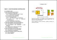
is 125 ms. (See Figure 20 for a more elaborate filter.) Finally, to<br />
improve the law conformance at very low signal levels and at low<br />
frequencies, C4 has been added to the offset compensation loop.<br />
+5V<br />
V OUT – (V)<br />
1.50<br />
1.25<br />
1.00<br />
0.75<br />
0.50<br />
0.25<br />
WITH FILTER<br />
ERROR<br />
(WITH FILTER)<br />
1<br />
0<br />
–1<br />
–2<br />
ERROR (<strong>dB</strong>)<br />
V IN<br />
0.5mV TO<br />
20V<br />
SINE<br />
AMPLITUDE<br />
C1<br />
10F<br />
+<br />
R1<br />
5k<br />
C3<br />
750pF<br />
4.7<br />
0.1F<br />
NC<br />
INP VPS ENB INT<br />
<strong>AD8307</strong><br />
INM COM OFS OUT<br />
FOR SLOPE AND<br />
INTERCEPT ADJUSTMENTS<br />
SEE FIGURE 17<br />
0<br />
–100 –80 –60 –40 –20 0 20<br />
INPUT LEVEL (<strong>dB</strong>m)<br />
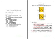
Figure 23. Results for 120 <strong>dB</strong> Measurement System<br />
Operation at <strong>Low</strong> Frequencies<br />
The <strong>AD8307</strong> provides excellent logarithmic conformance at<br />
signal frequencies that may be arbitrarily low, depending only<br />
on the values used for the input coupling capacitors. It may also<br />
be desirable to add a low-pass input filter in order to desensitize<br />
the log amp to HF signals. Figure 24 shows a simple arrangement,<br />
providing coupling with an attenuation of 20 <strong>dB</strong>; the intercept is<br />
shifted up by this attenuation, from –84 <strong>dB</strong>m to –64 <strong>dB</strong>m, and<br />
the input range is now 0.5 mV to 20 V (sine amplitude).<br />
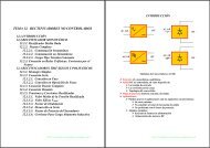
A high-pass 3 <strong>dB</strong> corner frequency of nominally 3 Hz is set by<br />
the 10 µF coupling capacitors C1 and C2, which are preferably<br />
tantalum electrolytics (note the polarity) and a low-pass 3 <strong>dB</strong><br />
corner frequency of 200 kHz (set by C3 and the effective resistance<br />
at the input of 1 kΩ). The –1% amplitude error points occur<br />
at 20 Hz and 30 kHz. These are readily altered to suit other applications<br />
by simple scaling. When C3 is zero, the low-pass corner is<br />
at 200 <strong>MHz</strong>. Note that the lower end of the dynamic range is<br />
improved by this capacitor, which essentially provides an HF short<br />
circuit at the input, thus significantly lowering the wideband noise;<br />
the noise reduction is about 2 <strong>dB</strong> compared to the case when the<br />
<strong>AD8307</strong> is driven from a 50 Ω source.<br />
To ensure that the output is free of post-demodulation ripple, it<br />
is necessary to lower the low-pass filter time constant. This is<br />
provided by C5; with the value shown, the output time constant<br />
+<br />
C2<br />
10F<br />
R2<br />
5k<br />
C4<br />
1F<br />
C5<br />
1F<br />
V OUT<br />
25mV/<strong>dB</strong><br />
NC = NO CONNECT<br />
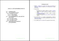
Figure 24. Connections for <strong>Low</strong> Frequency Operation<br />
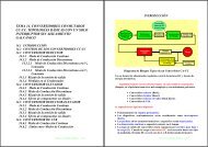
DC-Coupled Applications<br />
It may occasionally be necessary to provide response to dc inputs.<br />
Since the <strong>AD8307</strong> is internally dc-coupled, there is no fundamental<br />
reason why this is precluded. However, there is a practical<br />
constraint, which is that its inputs must be positioned about 2 V<br />
above the COM potential for proper biasing of the first stage. If<br />
it happens that the source is a differential signal at this level, it<br />
may be directly connected to the input. For example, a microwave<br />
detector can be ac-coupled at its RF input and its baseband load<br />
then automatically provided by the floating R IN and C IN of the<br />
<strong>AD8307</strong>, at about V P /2.<br />
Usually, the source will be a single-sided ground-referenced<br />
signal, and it will therefore be necessary to provide a negative<br />
supply for the <strong>AD8307</strong>. This can be achieved as shown in<br />
Figure 25. The output is now referenced to this negative supply,<br />
and it is necessary to provide an output interface that performs a<br />
differential-to-single-sided conversion. This is the purpose of<br />
the AD830. The slope may be arranged to be 20 mV/<strong>dB</strong>, when<br />
the output ideally runs from zero, for a dc input of 10 µV, to<br />
2.2 V for an input of 4 V. The <strong>AD8307</strong> is fundamentally insensitive<br />
to the sign of the input signal, but with this biasing scheme,<br />
the maximum negative input is constrained to about –1.5 V.<br />
The transfer function after trimming and with R7 = 0, is<br />
V 04 . V log V 10µ<br />
V<br />
OUT = ( ) 10 ( IN )<br />
V IN<br />
+5V<br />
TEMP<br />
R1<br />
4.7<br />
R2<br />
3.3k<br />
C2<br />
1F<br />
C1<br />
0.1F<br />
INP VPS ENB INT<br />
<strong>AD8307</strong><br />
INM COM OFS OUT<br />
VR2<br />
50k<br />
R5<br />
*<br />
*51k FOR<br />
20mV/<strong>dB</strong><br />
5k FOR<br />
100mV/<strong>dB</strong><br />
20mV/<strong>dB</strong><br />
+5V FOR 20mV/<strong>dB</strong><br />
+10V FOR 50mV/<strong>dB</strong><br />
+15V FOR 100mV/<strong>dB</strong><br />
–5V<br />
VP INT NC VN<br />
AD830<br />
X1 X2 Y1 Y2<br />
R7<br />
V OUT<br />
R7,R8:<br />
SEE TEXT<br />
AD589<br />
R3<br />
1k<br />
Q1<br />
2N3904<br />
–2V<br />
VR1<br />
2k<br />
C3<br />
0.1F<br />
R6<br />
32.4k<br />
VR3<br />
50k<br />
R9<br />
250<br />
R8<br />
–5V<br />
NC = NO CONNECT<br />
REV. B<br />
Figure 25. Connections for DC-Coupled Applications<br />
–17–