AD8307 Low Cost DCâ500 MHz, 92 dB Logarithmic Amplifier Data ...
AD8307 Low Cost DCâ500 MHz, 92 dB Logarithmic Amplifier Data ...
AD8307 Low Cost DCâ500 MHz, 92 dB Logarithmic Amplifier Data ...

Create successful ePaper yourself
Turn your PDF publications into a flip-book with our unique Google optimized e-Paper software.
<strong>AD8307</strong><br />
LOG AMP THEORY<br />
<strong>Logarithmic</strong> amplifiers perform a more complex operation than<br />
that of classical linear amplifiers, and their circuitry is significantly<br />
different. A good grasp of what log amps do, and how they do<br />
it, will avoid many pitfalls in their application. The essential<br />
purpose of a log amp is not to amplify, though amplification is<br />
utilized to achieve the function. Rather, it is to compress a signal<br />
of wide dynamic range to its decibel equivalent. It is thus a<br />
measurement device. A better term might be logarithmic<br />
converter, since its basic function is the conversion of a signal<br />
from one domain of representation to another, via a precise nonlinear<br />
transformation.<br />
<strong>Logarithmic</strong> compression leads to situations that may be confusing<br />
or paradoxical. For example, a voltage offset added to the<br />
output of a log amp is equivalent to a gain increase ahead of its<br />
input. In the usual case where all the variables are voltages, and<br />
regardless of the particular structure, the relationship between the<br />
variables can be expressed as:<br />
V V log V V<br />
(1)<br />
= ( )<br />
OUT Y IN X<br />
where:<br />
V OUT is the output voltage.<br />
V Y is the slope voltage; the logarithm is usually taken to baseten<br />
(in which case V Y is also the volts-per-decade).<br />
V IN is the input voltage.<br />
V X is the intercept voltage.<br />
All log amps implicitly require two references, here, V X and V Y ,<br />
which determine the scaling of the circuit. The absolute accuracy<br />
of a log amp cannot be any better than the accuracy of its<br />
scaling references. Equation 1 is mathematically incomplete in<br />
representing the behavior of a demodulating log amp such as<br />
the <strong>AD8307</strong>, where V IN has an alternating sign. However, the<br />
basic principles are unaffected, and we can safely use this as our<br />
starting point in the analyses of log amp scaling that follow.<br />
V OUT<br />
5V Y<br />
4V Y<br />
3V Y<br />
2V Y<br />
V Y<br />
V OUT = 0<br />
V IN = 10 –2 V X<br />
–40<strong>dB</strong>c<br />
–2V Y<br />
LOWER INTERCEPT<br />
V IN = V X<br />
0<strong>dB</strong>c<br />
V SHIFT<br />
V IN = 10 2 V X<br />
+40<strong>dB</strong>c<br />
V IN = 10 4 V X<br />
+80<strong>dB</strong>c<br />
LOG V IN<br />
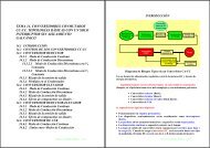
Figure 1. Ideal Log Amp Function<br />
Figure 1 shows the input/output relationship of an ideal log amp,<br />
conforming to Equation 1. The horizontal scale is logarithmic<br />
and spans a wide dynamic range, shown here as over 120 <strong>dB</strong>, or<br />
six decades. The output passes through zero (the log-intercept)<br />
at the unique value V IN = V X and would ideally become negative<br />
for inputs below the intercept. In the ideal case, the straight line<br />
describing V OUT for all values of V IN would continue indefinitely<br />
in both directions. The dotted line shows that the effect of adding<br />
an offset voltage V SHIFT to the output is to lower the effective<br />
intercept voltage V X . Exactly the same alteration could be achieved<br />
by raising the gain (or signal level) ahead of the log amp by the<br />
factor V SHIFT /V Y . For example, if V Y is 500 mV per decade<br />
(25 mV/<strong>dB</strong>), an offset of +150 mV added to the output will<br />
appear to lower the intercept by two tenths of a decade, or 6 <strong>dB</strong>.<br />
Adding an offset to the output is thus indistinguishable from<br />
applying an input level that is 6 <strong>dB</strong> higher.<br />
The log amp function described by Equation 1 differs from that<br />
of a linear amplifier in that the incremental gain ∂V OUT /∂V IN is a<br />
very strong function of the instantaneous value of V IN , as is<br />
apparent by calculating the derivative. For the case where the<br />
logarithmic base is e, we have:<br />
∂V<br />
∂V<br />
OUT<br />
IN<br />
V<br />
=<br />
V<br />
Y<br />
IN<br />
That is, the incremental gain is inversely proportional to the<br />
instantaneous value of the input voltage. This remains true for<br />
any logarithmic base, which is chosen as 10 for all decibelrelated<br />
purposes. It follows that a perfect log amp would be<br />
required to have infinite gain under classical small-signal (zeroamplitude)<br />
conditions. Less ideally, this result indicates that,<br />
whatever means are used to implement a log amp, accurate<br />
response under small-signal conditions (that is, at the lower end<br />
of the dynamic range) demands the provision of a very high<br />
gain-bandwidth product. A further consequence of this high<br />
gain is that, in the absence of an input signal, even very small<br />
amounts of thermal noise at the input of a log amp will cause a<br />
finite output for zero input, resulting in the response line curving<br />
away from the ideal shown in Figure 1 toward a finite baseline,<br />
which can be either above or below the intercept. Note that the<br />
value given for this intercept may be an extrapolated value, in<br />
which case the output may not cross zero, or even reach it, as is<br />
the case for the <strong>AD8307</strong>.<br />
While Equation 1 is fundamentally correct, a simpler formula is<br />
appropriate for specifying the calibration attributes of a log amp<br />
like the <strong>AD8307</strong>, which demodulates a sine wave input:<br />
VOUT = VSLOPE ( PIN<br />
− P0 )<br />
(3)<br />
where:<br />
V OUT is the demodulated and filtered baseband (video or RSSI)<br />
output.<br />
V SLOPE is the logarithmic slope, now expressed in V/<strong>dB</strong><br />
(typically between 15 mV/<strong>dB</strong> and 30 mV/<strong>dB</strong>).<br />
P IN is the input power, expressed in decibels relative to some<br />
reference power level.<br />
P 0 is the logarithmic intercept, expressed in decibels relative to<br />
the same reference level.<br />
The most widely used reference in RF systems is decibels above<br />
1 mW in 50 Ω, written <strong>dB</strong>m. Note that the quantity (P IN – P 0 ) is<br />
just <strong>dB</strong>. The logarithmic function disappears from the formula<br />
because the conversion has already been implicitly performed in<br />
stating the input in decibels. This is strictly a concession to<br />
popular convention; log amps manifestly do not respond to<br />
power (tacitly, power absorbed at the input), but rather to input<br />
voltage. The use of <strong>dB</strong>V (decibels with respect to 1 V rms)<br />
would be more precise, though still incomplete, since waveform<br />
is involved, too. Since most users think about and specify RF<br />
(2)<br />
REV. B<br />
–7–