

The Design of Matching Systems For Piezo Elements - Airmar ...
The Design of Matching Systems For Piezo Elements - Airmar ...
The Design of Matching Systems For Piezo Elements - Airmar ...

You also want an ePaper? Increase the reach of your titles
YUMPU automatically turns print PDFs into web optimized ePapers that Google loves.
Application<br />
Notes<br />
Ultrasonic Transducers<br />
Notes On <strong>The</strong> <strong>Design</strong> Of <strong>Matching</strong><br />
<strong>Systems</strong> <strong>For</strong> <strong>Piezo</strong> <strong>Elements</strong><br />
<strong>The</strong>se notes describe a simplified approach to match<br />
a piezo device to a source <strong>of</strong> power. <strong>The</strong> optimum<br />
matching circuit will result in maximum transmitted<br />
energy which will result in stronger echoes.<br />
Delivering power to a piezo device, such as a transducer<br />
for a ranging instrument, is relatively simple in a<br />
normal situation. If the fundamentals are understood,<br />
then special circumstances can also be<br />
accommodated in a straightforward manner.<br />
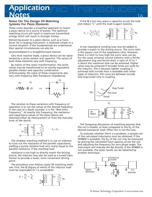
Like most reactive loads, a piezo device can be represented<br />
by a series resistor and capacitor. <strong>The</strong> values <strong>of</strong><br />
both these elements vary with frequency.<br />
By means <strong>of</strong> the classic transformation, the series<br />
values may be transformed to an exactly equivalent<br />
parallel resistor and capacitor combination.<br />
Unfortunately, the value <strong>of</strong> these components also<br />
vary with frequency (See Transducer Impedance).<br />
If the Q is too low, place a capacitor across the load<br />
and reduce “L” until the load is again resistive.<br />
1A<br />
A low impedance winding may now be added to<br />
provide a match to the driving source. <strong>The</strong> turns ratio<br />
is the square root <strong>of</strong> the impedance ratio. However,<br />
there is a limit to how high the turns ratio can be.<br />
<strong>For</strong> the usual universal wound inductor with a ferrite<br />
adjustment slug and ferrite shell, a ratio <strong>of</strong> 22 to 1<br />
is about the maximum that can be achieved. Higher<br />
ratios may be achieved if toroidal forms are used for<br />
the inductor. This is because tighter coupling is<br />
achieved with toroids than is available with other<br />
types <strong>of</strong> inductors. Pot cores are between toroids<br />
and slug-tuned coils in coupling.<br />
<strong>The</strong> solution to these variations with frequency <strong>of</strong><br />
operation is to use the values at the desired frequency.<br />
In the case <strong>of</strong> a depth sounder, it is the “Best Echo<br />
Frequency”. At exactly this frequency, the resistance<br />
and capacitance values <strong>of</strong> the piezo device are<br />
obtained either by measurement or from the manufacturer<br />
<strong>of</strong> the device.<br />
<strong>The</strong> simplest matching method is to use an inductor<br />
to tune out the reactance <strong>of</strong> the parallel capacitance,<br />
yielding a purely resistive load very nearly equal to the<br />
parallel resistance. If the resulting load<br />
resistance is too high to directly match the driving<br />
source, the inductor may also be used as a tuned transformer<br />
to provide a lower, more convenient driving<br />
point.<br />
<strong>The</strong> procedure now follows classic RF matching methods.<br />
First, the Q (figure <strong>of</strong> merit) <strong>of</strong> the inductor load<br />
must be reasonable (5-7 is acceptable).<br />
<strong>The</strong> foregoing discussions <strong>of</strong> matching assumes that<br />
the coil is lossless, at least compared to the R p <strong>of</strong> the<br />
desired transducer load. Often this is not the case.<br />
To evaluate whether there is a problem, a sample coil<br />
<strong>of</strong> the calculated inductance must be obtained. If the<br />
HP4800 is available, the R p <strong>of</strong> the coil may be measured<br />
by placing the calculated total capacity across the coil<br />
and adjusting the frequency for zero phase angle. <strong>The</strong><br />
instrument will indicate the Rp directly. If the HP4800 is<br />
not available, the same results can be obtained by<br />
another technique.<br />
© <strong>Airmar</strong> Technology Corporation • www.airmar.com
Ultrasonic Transducers<br />
Application<br />
Notes Continued<br />
Find the frequencies at which the response <strong>of</strong> the<br />
tuned circuit is down 3dB from peak response.<br />
<strong>The</strong> R p <strong>of</strong> the coil should now be considered to be<br />
in parallel with R p <strong>of</strong> the transducer.<br />
<strong>The</strong> coil inductance and resonating capacity must<br />
now be recalculated based on the lower load resistance<br />
presented by the parallel combination <strong>of</strong> the R p <strong>of</strong><br />
both the coil and transducer.<br />
Also, the division <strong>of</strong> the available output power<br />
must be considered. If the two R p ’s are equal, only one<br />
half the power developed is available to the transducer<br />
to put into the water. So it is desirable that the R p <strong>of</strong><br />
the coil be as high as possible compared to the R p <strong>of</strong><br />
the transducer.<br />
<strong>The</strong> advantages <strong>of</strong> this method <strong>of</strong> matching are:<br />
■ Minimum components —minimum cost<br />
2A<br />
■ Highest impedance in the connecting cable,<br />
hence the lowest I 2 R losses<br />
■ If the cable must be extended, a simple removal<br />
<strong>of</strong> fixed capacity is all that is required<br />
Another method which might be considered is using<br />
the series equivalent values <strong>of</strong> the piezo device. To do<br />
this, an inductor is placed in series with the piezo<br />
device whose reactance is equal to the reactance <strong>of</strong><br />
the equivalent series capacitance. This method presents<br />
the value <strong>of</strong> series resistance to the driving source.<br />
<strong>The</strong> disadvantage is that a second inductor is required<br />
because in the usual case, the series resistance is still<br />
higher than the required load impedance <strong>of</strong> semiconductor<br />
power sources. Also, the current through the<br />
load must pass through the effective series resistance<br />
<strong>of</strong> this (series) inductor, which increases the I 2 R losses,<br />
resulting in a net loss <strong>of</strong> power delivered to the load in<br />
the usual case.<br />
Example:<br />
Assume that a transducer is to be matched whose<br />
“Best Echo Frequency” is 196.0 kHz and the series<br />
R and X have been measured at that frequency as<br />
151 – j239 (C = 3400pf).<br />
Once the coil is designed and in place, the effectiveness<br />
may be checked by placing the equivalent parallel<br />
capacitance <strong>of</strong> the piezo device across the inductor.<br />
<strong>The</strong>n various resistors are placed across the inductor<br />
and the power dissipated is then calculated. A broad<br />
peak should be achieved at the value <strong>of</strong> the parallel<br />
resistance <strong>of</strong> the piezo device. If the power peak does<br />
not occur at the value <strong>of</strong> parallel resistance which the<br />
piezo device has at the frequency <strong>of</strong> interest, small<br />
adjustments in the turns ratio and/or the Q should be<br />
made.<br />
Since at resonance X C = X L , the inductor will have a<br />
reactance <strong>of</strong> 334.4 ohms<br />
Calculate Q <strong>of</strong> this situation<br />
© <strong>Airmar</strong> Technology Corporation • www.airmar.com
Ultrasonic Transducers<br />
Application<br />
Notes Continued<br />
This is too low so capacitance must be added. Let us<br />
calculate on the basis <strong>of</strong> a loaded Q <strong>of</strong> 6<br />
3A<br />
If parallel resistance is not used in the calculation,<br />
series resistance may be used. But the calculation is a<br />
bit more involved:<br />
1.<br />
2.<br />
Total C is now<br />
3.<br />
4. <strong>The</strong> above equations are combined into a single<br />
equation<br />
Added capacity must then be 9204 – 2483 = 6721pf<br />
<strong>The</strong> required primary impedance is calculated as 3.6<br />
ohms to match the driving transistor<br />
This is low enough so a slug tuned coil may be used.<br />
If a coil <strong>of</strong> 71.6mHy required 55 turns, then the primary<br />
would use 4.5 turns;<br />
<strong>The</strong> primary should be wound as tightly over the secondary<br />
as possible to obtain the best coupling. Use the<br />
start <strong>of</strong> the secondary coil as the high impedance end.<br />
Power into a piezo device:<br />
If the parallel resistance is known, power calculation<br />
is straightforward:<br />
Of course the voltage across the load will probably<br />
be measured with an oscilloscope and read as peak to<br />
peak voltage. <strong>The</strong>refore, it must be divided by 2.83 to<br />
change to RMS voltage.<br />
Considerations for matching systems<br />
during receive mode:<br />
Once the matching has been accomplished for transmit,<br />
what are the considerations for receiving? If the input<br />
impedance <strong>of</strong> the receiving section is higher by a large<br />
margin, then it may be tied directly across the tuned<br />
circuit used to match in transmit.<br />
If the receive input impedance margin is not large<br />
or is even small, then other methods must be used to<br />
achieve the maximum performance <strong>of</strong> which the piezo<br />
device is capable. Also, provisions must be made to<br />
prevent the transmit voltage from destroying the<br />
input device(s) <strong>of</strong> the receiver.<br />
If the coupling <strong>of</strong> the transformer is high, a lower<br />
“Q” may operate satisfactorily. Reduce the capacity<br />
added in steps, increasing the inductance <strong>of</strong> the<br />
secondary in steps to maintain resonance. Keep the<br />
primary inductance constant. In the extreme it may be<br />
possible to resonate just the capacity <strong>of</strong> the transducer<br />
without adding any external capacitance. This will yield<br />
higher turns ratios and if the coupling is tight enough,<br />
will also yield more output voltage (power).<br />
Note, however, that at Q values <strong>of</strong> 7 or less, the<br />
equation no longer holds. Until such time as an application<br />
note describing techniques <strong>of</strong> calculating such low<br />
Q matching systems is developed, proceed carefully,<br />
step by step, in developing these matching systems<br />
by empirical methods.<br />
35 Meadowbrook Drive, Milford, NH 03055-4613 USA<br />
Tel 603-673-9570 ■ Fax 603-673-4624<br />
Web: www.airmar.com ■ e-mail: sales@airmar.com<br />
© <strong>Airmar</strong> Technology Corporation


