

Underwater Communications.pdf
Underwater Communications.pdf
Underwater Communications.pdf

Create successful ePaper yourself
Turn your PDF publications into a flip-book with our unique Google optimized e-Paper software.
<strong>Underwater</strong><br />
<strong>Communications</strong><br />
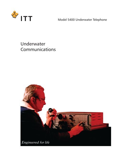
Model 5400 <strong>Underwater</strong> Telephone
Model 5400 <strong>Underwater</strong> Telephone<br />
The Model 5400 UWT is a compact, high-power<br />
acoustic underwater telephone for single sideband<br />
voice and modulated CW operation. Fully synthesized,<br />
the Model 5400 UWT covers a frequency range of<br />
5 to 45* kHz, selectable in 1 Hz increments plus<br />
the AN/WQC and ARD-8000 frequencies. It is fully<br />
compatible with AN/UQC, AN/BQC, and ATM-504<br />
series.<br />
FEATURES<br />
Advanced Digital Signal Processing results in a large<br />
number of selectable functions and frequencies with<br />
superior voice quality.<br />
AN/UQC compatible default settings: In default<br />
mode, the system is compatible with AN/UQC series<br />
systems (carrier frequency 8.087 kHz, USB, 200 watt<br />
output power). TIPE default frequencies are also<br />
selected.<br />
TIPE (Transponder, Interrogator and Pinger/Echo<br />
Sounder) Modes provide automatic ranging, tracking<br />
pinger, and when used with a vertically oriented<br />
transducer, depth below the surface or altitude<br />
above the bottom. It also operates on operator<br />
selected frequencies between 5 - 45* kHz.<br />
AN/WQC Mode: In WQC Mode the system can<br />
communicate with the AN/WQC system and provide<br />
automatic ranging against an ARD-8000.<br />
If used with an external power amplifier, the system<br />
is capable of the same output acoustic source levels<br />
as the AN/WQC.<br />
Emergency <strong>Underwater</strong> Telephone Interface via a<br />
connector on the front panel allows access to a<br />
designated transducer by a compatible telephone.<br />
Interface to External Equipment via rear panel connections:<br />
For XMTR Input/Output, the telephone’s<br />
signal can be routed to an external power amplifier. An<br />
external source can utilize the Model 5400 UWT’s<br />
power amplifier and transducer(s) for transmission.<br />
An Auxiliary Transducer Input allows an independent<br />
user access to the transducer not currently selected<br />
by the Model 5400 UWT. In addition, the Model<br />
5400 UWT can mute external equipment when<br />
transmitting. The Receiver Output allows unprocessed<br />
data to be fed to external equipment for<br />
processing.<br />
Interface to Data <strong>Communications</strong> Equipment by<br />
customer Data <strong>Communications</strong> Equipment (DCE)<br />
via an RS-232/RS-422 Serial Interface: Baud rate can<br />
be set from the front panel.<br />
Up to four remote control stations can be accessed.<br />
The fourth remote control port can be used for DCE<br />
via an RS-232/RS-422 interface.<br />
Built-in test Performance Monitor and Fault Location:<br />
The UWT automatically performs a self-diagnostic<br />
and front panel lamp test routine. If an error is<br />
detected, one of six error messages will be displayed,<br />
and the operator can perform a further series of<br />
tests to isolate the fault to circuit board level.<br />
Two transducer outputs are standard on the Model<br />
5400 UWT. For installations requiring multiple transducers,<br />
a separate Transducer Interface Unit is available.<br />
The Model 5400 UWT is housed in a drip-proof cabinet,<br />
suitable for rack mount as well as table top installation.<br />
Cooling is by forced air from an internal fan.<br />
The system is designed to Best Commercial Standards,<br />
using Military Specifications as design guidelines.<br />
Mean Time Between Failure (MTBF) predicted at 2,600<br />
hours when calculated in accordance with MIL-HDBK-217E,<br />
Parts Count Method.<br />
*May be limited by the bandwidth of the installed transducer(s).<br />
2
AVAILABLE OPTIONS<br />
Remote Control Unit: The Model 5400 UWT can<br />
be controlled from up to four remote locations. The<br />
Remote Control Unit can perform all the functions of<br />
the master station, except for the EMERGENCY UWT<br />
interface which is disabled. The Remote Control Unit<br />
can be installed either in a standard 19-inch rack, or be<br />
bulkhead mounted. Power requirements are 110 or 220<br />
V, 50-60 Hz.<br />
OPERATOR INTERFACE<br />
All operator controls are located on the front panel.<br />
The front panel has adjustable backlighting, except<br />
for Power On/Off, speaker Volume, Squelch and TIPE<br />
Transmission Rate, all system operator controls are<br />
membrane switches. Frequently used functions have<br />
dedicated controls, while less frequently used functions<br />
are selected by numeric code entries on the keypad. This<br />
makes operation simple while allowing flexibility and a<br />
virtually unlimited number of functions. Functions selected<br />
and parameter values are displayed on red LEDs. The<br />
frequency and Range displays are also used for display of<br />
warning messages and for results of initiated tests.<br />
Model SP23LT & SB31CT Transducers<br />
Transducers: A selection of transducers is available, to<br />
suit a variety of applications.<br />
Transducer Interface Unit (TIU): Where more than two<br />
transducers are to be connected (typically sector transducers),<br />
an interface unit is available. The TIU connects<br />
to the telephone transceiver via transducer position #2<br />
and is controlled from the UWT front panel.<br />
Mode changes and modifications to operating parameters<br />
are accomplished by touch switches and code entries<br />
on the front panel.<br />
Up to 50 operator selected front panel set-ups<br />
(frequency/mode) can be stored in RAM for easy recall<br />
at any time. Five operator selectable output power levels,<br />
200-, 100-, 60-, 10-, and 2-watts provide communication<br />
at ranges to 20,000 yards.<br />
Optional AC/DC<br />
Power Supply<br />
AC/DC Power Supply: AC to DC power supplies are<br />
optionally available for operation from 110 or 220 Vac.<br />
The power supply unit is configured for installation in a<br />
19-inch rack.<br />
Auxiliary Power Unit: This unit contains the WQC-2A<br />
equivalent power amplifier, output transformer and<br />
115VacC/28Vdc power Supply.<br />
Headset with Boom Microphone: The headset with<br />
boom microphone comes with a six-foot coil cord and<br />
belt clip push-to-talk switch.<br />
3
VOICE & CW COMMUNICATION<br />
TYPICAL APPLICATIONS<br />
Voice and Continuous Wave (CW) communication is the<br />
Model 5400 UWT’s primary application. Communication<br />
can be established between any two points (surface<br />
ships, submarines, fixed installations, or any combination<br />
of these) in the same body of water at ranges to 20,000<br />
yards. Operating frequencies are selectable.<br />
Broad frequency range, adjustable output power, and<br />
selectable USB/LSB modulation, allows the Model 5400<br />
UWT to provide discrete communication when multiple<br />
telephones are used in the same operating area as<br />
well as communication with diver carried underwater<br />
telephones.<br />
CW transmission is available from either the front panel<br />
push button, or by Morse key via a back panel connector.<br />
The system is designed for simultaneous voice and TIPE<br />
operation and, when proper frequency separation is<br />
maintained, mutual interference is minimized.<br />
TIPE OPERATION<br />
While operating in any TIPE submode, voice operation<br />
retains priority; the voice receiving channel remains<br />
audible and immediate voice transmission is available<br />
via the selected microphone.<br />
Transponder/Interrogator: The Transponder/<br />
Interrogator Modes are used for ranging between<br />
two platforms equipped with Model 5400 UWTs, or<br />
between a Model 5400 UWT and any other acoustic<br />
device capable of generating a compatible interrogation<br />
or response signal.<br />
Interrogation pulses can be transmitted manually, or<br />
automatically at a rate of 1 to 60 interrogations per<br />
minute. The rate is adjustable by means of the RATE<br />
potentiometer control.<br />
Pinger/Echo Sounder: In this mode, the telephone can<br />
be used as an acoustic beacon by transmitting a signal<br />
at a selected frequency. Pulses can be transmitted<br />
manually, or automatically at a rate of<br />
1 to 60 pulses per minute.<br />
Echo sounder operation is the same as Pinger<br />
operation except that the transmitted signal<br />
is directed either up or down (to<br />
the surface or to the bottom)<br />
by a directional transducer. The<br />
telephone calculates the delay of<br />
the return signal and displays<br />
the depth or altitude in yards or<br />
meters.<br />
• Surface ship to surface ship<br />
• Surface ship to submarine<br />
• Submarine to submarine<br />
• Acoustic Beacon<br />
• Either platform<br />
interrogating<br />
the other for<br />
ranging.<br />
TELEMETRY<br />
The Model 5400 UWT’s transceiver<br />
and transducer(s) can be used to<br />
transmit and receive data from<br />
peripheral equipment via a connector<br />
located on the telephone’s<br />
back panel.<br />
Typical applications are interrogation<br />
of coded transponders, and<br />
Identification Friend or Foe (IFF).<br />
Frequency coverage is 5 to 45* kHz<br />
in 1 Hz increments.<br />
*May be limited by the bandwidth of the<br />
installed transducer(s).<br />
• Echo<br />
Sounder Instrumentation<br />
Package<br />
4
Power On/Off<br />
illuminated<br />
push-button.<br />
Speaker.<br />
Microphone<br />
Voice/CW<br />
Speaker<br />
On/Off<br />
Volume<br />
Control<br />
Squelch<br />
Control<br />
Frequency Control Panel:<br />
Frequency Display<br />
Numeric Keypad<br />
Frequency Adjust<br />
Baud Rate Adjust<br />
Save Settings<br />
Recall Saved Settings<br />
Restore Defaults<br />
Function Codes<br />
Illumination<br />
Control<br />
CW Transmit<br />
Key<br />
Headset<br />
Connector<br />
Emergency Telephone connector<br />
• In the event of a system failure or loss of<br />
power, the EMERGENCY Connector provides<br />
direct access to a designated transducer by a<br />
compatible emergency underwater telephone<br />
Station<br />
(Local/<br />
Remote)<br />
TIPE Control Panel:<br />
Rate Control<br />
Range Display<br />
Auto/Manual<br />
Select<br />
TIPE Transmit<br />
Mode Select<br />
Transducer Control Panel:<br />
Transducer Power<br />
Transducer Select<br />
Transmitter<br />
Control Panel:<br />
Transmitter Operation Mode<br />
Linear/Compression Mode Select<br />
Model 5400-1 <strong>Underwater</strong> Telephone<br />
5
Applications of the Model 5400 <strong>Underwater</strong> Telephone<br />
Model 5400-2 <strong>Underwater</strong> Telephone Transceiver<br />
The ITT Model 5400 <strong>Underwater</strong> Telephone transceiver has been selected by Raytheon for the U.S. Navy New Attack<br />
Submarine program (NSSN), the Virginia Class SSN. This underwater telephone transceiver, designated Model 5400-2<br />
has the following features:<br />
• Master/Slave Operation between two<br />
Model-5400-2 transceivers<br />
• Master/Slave selected by host computer<br />
• Utilizes sonar system power amplifier<br />
• Thermal warning/thermal overload sensor<br />
• Battle short capability/indication<br />
• Independent selection of transmit/receive<br />
transducers<br />
• High/low power selection control<br />
• Improved ranging accuracy<br />
• Concurrent high/low dual band receive<br />
capability<br />
• Ruggedized for environment condition<br />
Master/Slave Control Interface<br />
(Master or Slave)<br />
J11<br />
(Slave or Master)<br />
J11<br />
Model 5400-2<br />
<strong>Underwater</strong><br />
Telephone<br />
Model 5400-2<br />
<strong>Underwater</strong><br />
Telephone<br />
J7 J4 J3 J6 J5 J17<br />
J7 J4 J3 J6 J5 J17<br />
+28Vdc<br />
H.F. Receive Signal Input<br />
Low Level Xmit Output<br />
RS-422 System Control Interface<br />
L.F. Receive Signal Input<br />
Battleshort Interlink Signal<br />
+28Vdc<br />
H.F. Receive Signal Input<br />
Low Level Xmit Output<br />
RS-422 System Control Interface<br />
L.F. Receive Signal Input<br />
Battleshort Interlink Signal<br />
Model 5400/WQC <strong>Underwater</strong><br />
Telephone System<br />
Prime Power<br />
115 Vac<br />
Remote<br />
Control Unit<br />
ITT has been selected by Empresa Nacional Bazan,<br />
Factoria Naval de Ferrol to provide the Model<br />
5400/WQC <strong>Underwater</strong> Telephone System for the<br />
F-100 Frigate Program. The Model 5400/WQC<br />
System is a modern, low life cycle cost NDI/COTS<br />
underwater communications system, which is<br />
equivalent to, or exceeds, the performance and<br />
functionality of the AN/WQC-2 system. The Model<br />
5400/WQC <strong>Underwater</strong> Telephone System is a<br />
complete systems approach consisting of the<br />
Model 5400-1 Main Unit/ Transceiver, the Auxiliary<br />
Power Unit, Remote Control Unit, the TR-232<br />
for LF operation, and the ITT SB31CT HF band<br />
omni-directional transducer .<br />
Prime Power<br />
115 Vac<br />
Main Unit/<br />
Transceiver<br />
Auxiliary Power<br />
Unit<br />
Transducers<br />
TR-232<br />
SB31CT<br />
6
5400-1 <strong>Underwater</strong> Telephone Specifications<br />
Frequency Range (XMTR & RCVR)<br />
Frequency,<br />
Operator Selectable 5-45 kHz in 1 Hz steps plus<br />
WQC Mode<br />
1.45 - 3.1 kHz<br />
Accuracy<br />
Summary of ITT Model 5400/WQC System<br />
Characteristic<br />
Model 5400/WQC System<br />
Power 115 Vac +/- 10%<br />
60 Hz, single phase<br />
25A max<br />
Warm Up Time<br />
Heat Dissipation<br />
Frequency Range<br />
High Band<br />
Low Band<br />
Transmit Output Power<br />
Type Single Sideband<br />
Rated<br />
Maximum<br />
Max Audio Output Power<br />
Control Station 2.5W<br />
Remote Station 2.5W<br />
6 seconds to complete built-in test functions<br />
700W (at full power)<br />
8.3 kHz to 11.1 kHz<br />
1.45 kHz to 3.10 kHz<br />
1400 VA, 1.4 kHz to 11.1 kHz<br />
1500 VA<br />
Receiver Capability<br />
Type Reception<br />
Sensitivity<br />
High Band<br />
Low Band<br />
Load Impedance<br />
Drive Capability<br />
Size & Weight<br />
Main Unit/Transceiver<br />
Remote Control Unit<br />
Auxiliary Power Unit<br />
Single Sideband<br />
-160 dBV, 1 Hz BW for 10 dB SNR<br />
-157 dBV, 1 Hz BW for 10 dB SNR<br />
30 to 50 Ω at<br />
resonant frequency<br />
5.22in. H, 17in. W, 13.9in. D, Weight - 35 lb.<br />
5.22in. H, 17in. W, 6in. D, Weight- 11 lb.<br />
8.75in. H, 17in. W, 20in. D, Weight- 60 lb.<br />
Model 5400/WQC Auxiliary Amplifier Unit<br />
The Auxiliary Power Unit contains the WQC-2A-equivalent<br />
power amplifier, output transformer and power<br />
supplies. The power amplifier utilizes a proven<br />
COTS-based auxiliary power unit with a power amplifier<br />
module of the PWM type. It is capable of delivering<br />
up to 1500 VA into highly reactive loads. The PWM<br />
technology provides a very efficient amplifier (85-90%)<br />
which maintains it’s efficiency over a wide range of<br />
operating frequencies and also when driving highly<br />
reactive transducer loads. It operates from +48 Vdc.<br />
The unit includes a high power switching type power<br />
supply that is capable of delivering up to 1800 watts<br />
of +48 Vdc power.<br />
An output transformer is provided to match the output<br />
of the power amplifier to the WQC band transducer<br />
loads. It is capable of operating at the 1400 VA power<br />
level over the frequency range of 1.4kHz to 11.1khz.<br />
An output relay switching matrix is also provided to<br />
select at least four different transducers. Transducer<br />
selection control is provided in the Model 5400-1<br />
transceiver.<br />
The Model 5400-1 transceiver has a built-in transmit/<br />
receive switch, however, in order to confine the high<br />
voltage to the power amplifier chassis, a T/R switch is<br />
provided within the Auxiliary Power Unit.<br />
The high power amplifier will receive input drive signals<br />
by means of an existing 200 watt transmit power<br />
amplifier in the Main Unit which will be retained as<br />
a standby, redundant power amplifier in the event of<br />
main power amplifier failure.<br />
CLEARED for open publication #04-S-1041<br />
ITT Corporation - Electronic Systems<br />
2645 South 300 West<br />
Salt Lake City UT 84115<br />
Telephone (801) 486-7481 • Fax (801) 484-3301<br />
E-mail: edoslc.marketing@edocorp.com • www.es.itt.com<br />
Specifications subject to change without notice. February 08


