

Selecting the right CMOS analog switch - AN638
Selecting the right CMOS analog switch - AN638
Selecting the right CMOS analog switch - AN638

You also want an ePaper? Increase the reach of your titles
YUMPU automatically turns print PDFs into web optimized ePapers that Google loves.
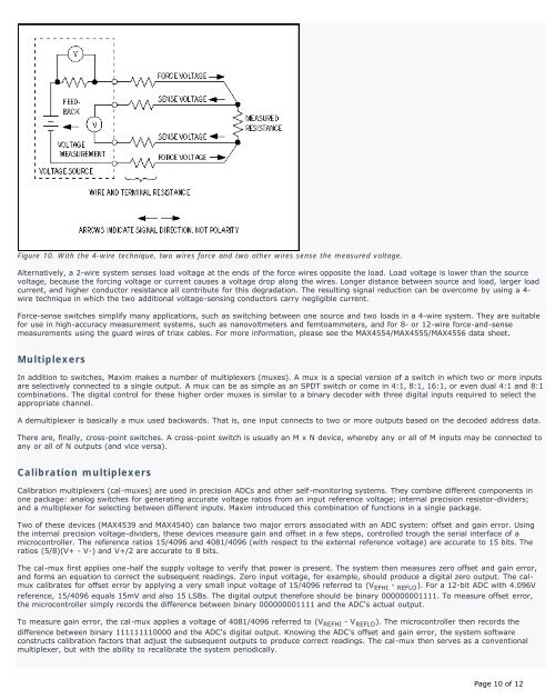
Figure 10. With <strong>the</strong> 4-wire technique, two wires force and two o<strong>the</strong>r wires sense <strong>the</strong> measured voltage.<br />
Alternatively, a 2-wire system senses load voltage at <strong>the</strong> ends of <strong>the</strong> force wires opposite <strong>the</strong> load. Load voltage is lower than <strong>the</strong> source<br />
voltage, because <strong>the</strong> forcing voltage or current causes a voltage drop along <strong>the</strong> wires. Longer distance between source and load, larger load<br />
current, and higher conductor resistance all contribute for this degradation. The resulting signal reduction can be overcome by using a 4-<br />
wire technique in which <strong>the</strong> two additional voltage-sensing conductors carry negligible current.<br />
Force-sense <strong>switch</strong>es simplify many applications, such as <strong>switch</strong>ing between one source and two loads in a 4-wire system. They are suitable<br />
for use in high-accuracy measurement systems, such as nanovoltmeters and femtoammeters, and for 8- or 12-wire force-and-sense<br />
measurements using <strong>the</strong> guard wires of triax cables. For more information, please see <strong>the</strong> MAX4554/MAX4555/MAX4556 data sheet.<br />
Multiplexers<br />
In addition to <strong>switch</strong>es, Maxim makes a number of multiplexers (muxes). A mux is a special version of a <strong>switch</strong> in which two or more inputs<br />
are selectively connected to a single output. A mux can be as simple as an SPDT <strong>switch</strong> or come in 4:1, 8:1, 16:1, or even dual 4:1 and 8:1<br />
combinations. The digital control for <strong>the</strong>se higher order muxes is similar to a binary decoder with three digital inputs required to select <strong>the</strong><br />
appropriate channel.<br />
A demultiplexer is basically a mux used backwards. That is, one input connects to two or more outputs based on <strong>the</strong> decoded address data.<br />
There are, finally, cross-point <strong>switch</strong>es. A cross-point <strong>switch</strong> is usually an M x N device, whereby any or all of M inputs may be connected to<br />
any or all of N outputs (and vice versa).<br />
Calibration multiplexers<br />
Calibration multiplexers (cal-muxes) are used in precision ADCs and o<strong>the</strong>r self-monitoring systems. They combine different components in<br />
one package: <strong>analog</strong> <strong>switch</strong>es for generating accurate voltage ratios from an input reference voltage; internal precision resistor-dividers;<br />
and a multiplexer for selecting between different inputs. Maxim introduced this combination of functions in a single package.<br />
Two of <strong>the</strong>se devices (MAX4539 and MAX4540) can balance two major errors associated with an ADC system: offset and gain error. Using<br />
<strong>the</strong> internal precision voltage-dividers, <strong>the</strong>se devices measure gain and offset in a few steps, controlled trough <strong>the</strong> serial interface of a<br />
microcontroller. The reference ratios 15/4096 and 4081/4096 (with respect to <strong>the</strong> external reference voltage) are accurate to 15 bits. The<br />
ratios (5/8)(V+ - V-) and V+/2 are accurate to 8 bits.<br />
The cal-mux first applies one-half <strong>the</strong> supply voltage to verify that power is present. The system <strong>the</strong>n measures zero offset and gain error,<br />
and forms an equation to correct <strong>the</strong> subsequent readings. Zero input voltage, for example, should produce a digital zero output. The calmux<br />
calibrates for offset error by applying a very small input voltage of 15/4096 referred to (V EFHI - REFLO ). For a 12-bit ADC with 4.096V<br />
reference, 15/4096 equals 15mV and also 15 LSBs. The digital output <strong>the</strong>refore should be binary 000000001111. To measure offset error,<br />
<strong>the</strong> microcontroller simply records <strong>the</strong> difference between binary 000000001111 and <strong>the</strong> ADC's actual output.<br />
To measure gain error, <strong>the</strong> cal-mux applies a voltage of 4081/4096 referred to (V REFHI - V REFLO ). The microcontroller <strong>the</strong>n records <strong>the</strong><br />
difference between binary 111111110000 and <strong>the</strong> ADC's digital output. Knowing <strong>the</strong> ADC's offset and gain error, <strong>the</strong> system software<br />
constructs calibration factors that adjust <strong>the</strong> subsequent outputs to produce correct readings. The cal-mux <strong>the</strong>n serves as a conventional<br />
multiplexer, but with <strong>the</strong> ability to recalibrate <strong>the</strong> system periodically.<br />
Page 10 of 12


