

A Matrix-Fed Circular Array for Continuous Scanning
A Matrix-Fed Circular Array for Continuous Scanning
A Matrix-Fed Circular Array for Continuous Scanning

Create successful ePaper yourself
Turn your PDF publications into a flip-book with our unique Google optimized e-Paper software.
SHELEG: MATRIX-FED CIRCULAR ARRAY FOR CONTINUOUS SCANNING 201 7<br />
symmetry, it can be used to scan a beam in discrete steps<br />
through a full 360” without the variations in gain and pattern<br />
shape that occur when four linear arrays are used, each<br />
scanning through a single quadrant. The purpose of this<br />
study was to determine some of the possibilities and also<br />
the limitations of scanning with circular arrays and, in<br />
particular, to demonstrate the use of the Butler matrix in<br />
feeding the elements of the array. The idea of using a Butler<br />
matrix <strong>for</strong> this purpose is due to Shelton [l], who showed<br />
that it permitted the <strong>for</strong>mation of a narrow radiated beam<br />
that could then be scanned essentially like the beam from a<br />
linear array, by the operation of phase shifters alone.<br />
The operation of a Butler-matrix-fed circular array<br />
(multimode array) is fist described heuristically in terms of<br />
“modes” and then, more satisfactorily, by considering the<br />
distribution of currents impressed on the radiating elements<br />
by the matrix. In addition, calculations were made to show<br />
how the radiation pattern of the multimode array varies as<br />
it is scanned continuously, rather than in discrete steps.<br />
The experimental portion of this program was per<strong>for</strong>med<br />
at L-band with a circular array of 32 dipoles around a conducting<br />
cylinder. Sidelobe level control was shown by using<br />
different amplitude tapers over the illuminated portion of<br />
the array.<br />
THEORY OF OPERATION<br />
The principles involved in scanning a multimode array<br />
are most easily seen by considering not an array, but a con-<br />
tinuous distribution of current. When this distribution is<br />
expressed as a Fourier series, in general idnite, each term<br />
represents a current mode uni<strong>for</strong>m in amplitude but having<br />
a phase varying linearly with angle. The radiation pattern of<br />
each mode has the same <strong>for</strong>m as the current mode itself, and<br />
these pattern modes are the Fourier components of the<br />
radiation pattern of the original distribution. The expression<br />
of the radiation pattern as the sum of modes of this<br />
<strong>for</strong>m is then seen to be analogous to the summation of the<br />
contribution made to the pattern of a linear array by its<br />
elements, so the operation of a multimode array can be explained<br />
by referring to an equivalent linear array.<br />
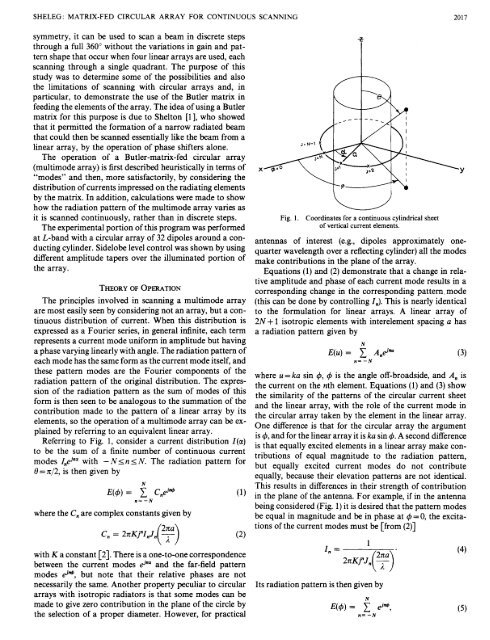
Referring to Fig. 1, consider a current .distribution I(a)<br />
to be the sum of a finite number of continuous current<br />
modes Z,@ with -NI~ I N. The radiation pattern <strong>for</strong><br />
8=x/2, is then given by<br />
N<br />
n= -N<br />
where the C, are complex constants given by<br />
with K a constant [2]. There is a one-to-one correspondence<br />
between the current modes F and the far-field pattern<br />
modes d*, but note that their relative phases are not<br />
necessarily the same. Another property peculiar to circular<br />
arrays with isotropic radiators is that some modes can be<br />
made to give zero contribution in the plane of the circle by<br />
the selection of a proper diameter. However, <strong>for</strong> practical<br />
Fig. 1.<br />
3<br />
Coordinates <strong>for</strong> a continuous cylindrical sheet<br />
of vertical current elements.<br />
antennas of interest (e.g., dipoles approximately onequarter<br />
wavelength over a reflecting cylinder) all the modes<br />
make contributions in the plane of the array.<br />
Equations (1) and (2) demonstrate that a change in relative<br />
amplitude and phase of each current mode results in a<br />
corresponding change in the corresponding pattern. mode<br />
(this can be done by controlling In). This is nearly identical<br />
to the <strong>for</strong>mulation <strong>for</strong> linear arrays. A linear array of<br />
2N + 1 isotropic elements with interelement spacing a has<br />
a radiation pattern given by<br />
N<br />
E(u) = 2 And”<br />
n= -N<br />
where u= ka sin 4, 4 is the angle off-broadside, and A, is<br />
the current on the nth element. Equations (1) and (3) show<br />
the similarity of the patterns of the circular current sheet<br />
and the linear array, with the role of the current mode in<br />
the circular array taken by the element in the linear array.<br />
One difference is that <strong>for</strong> the circular array the argument<br />
is 4, and <strong>for</strong> the linear array it is ka sin 4. A second difference<br />
is that equally excited elements in a linear array make contributions<br />
of equal magnitude to the radiation pattern,<br />
but equally excited current modes do not contribute<br />
equally, because their elevation patterns are not identical.<br />
This results in differences in their strength of contribution<br />
in the plane of the antenna. For example, if in the antenna<br />
being considered (Fig. 1) it is desired that the pattern modes<br />
be equal in magnitude and be in phase at 4 = 0, the excitations<br />
of the current modes must be [from (2)]<br />
Its radiation pattern is then given by<br />
1<br />
N<br />
E(4) = 1 &*,<br />
n= -N


