

A Matrix-Fed Circular Array for Continuous Scanning
A Matrix-Fed Circular Array for Continuous Scanning
A Matrix-Fed Circular Array for Continuous Scanning

Create successful ePaper yourself
Turn your PDF publications into a flip-book with our unique Google optimized e-Paper software.
~<br />
(degrees)<br />
2020<br />
PROCEEDINGS OF THE IEEE, NOVEMBER 1968<br />
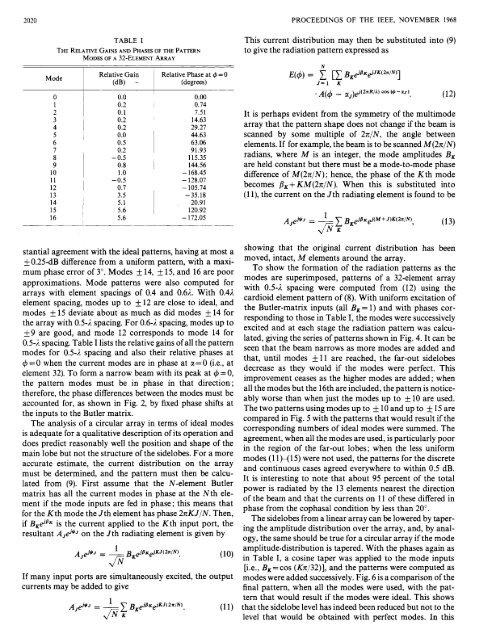
TABLE I<br />
THE RELATIVE GAINS AND PHASES OF THE PATTERN<br />
MODES OF A JZ-ELEMENT ARRAY<br />
~<br />
1 Relative Gain<br />
Mode<br />
I (dB) -<br />
Relative Phase at 4 = 0<br />
I<br />
0<br />
i<br />
0.0<br />
0.00<br />
1<br />
0.2<br />
I 0.74<br />
2<br />
0.1<br />
7.51<br />
3<br />
I 0.2<br />
14.63<br />
4<br />
0.2<br />
29.27<br />
5<br />
0.0<br />
44.63<br />
6<br />
0.5<br />
63.06<br />
7<br />
0.2<br />
91.93<br />
8 - 0.5<br />
115.35<br />
9<br />
0.8<br />
I 144.56<br />
10<br />
- 168.45<br />
11<br />
-0.5 - 128.07<br />
12<br />
I 0.7 - 105.74<br />
13<br />
3.5<br />
-35.18<br />
14<br />
5.1<br />
20.91<br />
15<br />
I<br />
I<br />
5.6<br />
120.92<br />
16<br />
5.6 - 172.05<br />
This current distribution may then be substituted into (9)<br />
to give the radiation pattern expressed as<br />
N<br />
E(4) = 1 [X B &BK&'JK(~~IN)<br />
J=l<br />
K<br />
K 1<br />
. A(C#J - uJ)&'(2WA) cm(4-a~)<br />
(12)<br />
It is perhaps evident from the symmetry of the multimode<br />
array that the pattern shape does not change if the beam is<br />
scanned by some multiple of 27r/N, the angle between<br />
elements. If <strong>for</strong> example, the beam is to be scanned M(27r/N)<br />
radians, where M is an integer, the mode amplitudes B K<br />
are held constant but there must be a mode-to-mode phase<br />
difference of M(24N); hence, the phase of the Kth mode<br />
becomes jlK+ KM(27rIN). When this is substituted into<br />
(1 l), the current on the Jth radiating element is found to be<br />
A ,$*J<br />
= -<br />
1 1 B &'BK&'(M+J K(277IN)<br />
K 7 (13)<br />
f i K<br />
stantial agreement with the ideal patterns, having at most a<br />
- f0.25dB difference from a uni<strong>for</strong>m pattern, with a maxi-<br />
mum phase error of 3". Modes * 14, * 15, and 16 are poor<br />
approximations. Mode patterns were also computed <strong>for</strong><br />
arrays withelement spacings of 0.4 and 0.62. With 0.42<br />
element spacing, modes up to f 12 are close to ideal, and<br />
modes * 15 deviate about as much as did modes f 14 <strong>for</strong><br />
the array with 0.5-1 spacing. For 0.6-2 spacing, modes up to<br />
*9 are good, and mode 12 corresponds to mode 14<strong>for</strong><br />
0.54 spacing. Table I lists the relative gains of all the pattern<br />
modes <strong>for</strong> 0.5-2 spacing and also their relative phases at<br />
4 = 0 when the current modes are in phase at u,= 0 (i.e., at<br />
element 32). To <strong>for</strong>m a narrow beam with its peak at C#J = 0,<br />
the pattern modes must be in phase in that direction;<br />
there<strong>for</strong>e, the phase differences between the modes must be<br />
accounted <strong>for</strong>, as shown in Fig. 2, by fixed phase shifts at<br />
the inputs to the Butler matrix.<br />
The analysis of a circular array in terms of ideal modes<br />
is adequate <strong>for</strong> a qualitative description of its operation and<br />
does predict reasonably well the position and shape of the<br />
main lobe but not the structure of the sidelobes. For a more<br />
accurate estimate, the current distribution on the array<br />
must be determined, and the pattern must then be calcu-<br />
lated from (9). First assume that the N-element Butler<br />
matrix has all the current modes in phase at the Nth element<br />
if the mode inputs are fed in phase; this means that<br />
<strong>for</strong> the Kth mode the Jth element has phase 27rKJIN. Then,<br />
if BKBBR is the current applied to the Kth input port, the<br />
resultant A Jd*J on the Jth radiating element is given by<br />
A~@J - 1 B &'BK&'KJ(~WN).<br />
f i K<br />
(10)<br />
If many input ports are simultaneously excited, the output<br />
currents may be added to give<br />
A,&'J - 1 1 B &'SK&'KJ(~~IN).<br />
K (11)<br />
f i K<br />
showing that the original current distribution has been<br />
moved, intact, M elements around the array.<br />
To show the <strong>for</strong>mation of the radiation patterns as the<br />
modes are superimposed, patterns of a 32-element array<br />
with 0.54 spacing were computed from (12) using the<br />
cardioid element pattern of (8). With uni<strong>for</strong>m excitation of<br />
the Butler-matrix inputs (all BK= 1) and with phases corresponding<br />
to those in Table I, the modes were successively<br />
excited and at each stage the radiation pattern was calcu-<br />
lated, giving the series of patterns shown in Fig. 4. It can be<br />
seen that the beam narrows as more modes are added and<br />
that, until modes &- 11 are reached, the far-out sidelobes<br />
decrease as they would if the modes were perfect. This<br />
improvement ceases as the higher modes are added ; when<br />
all the modes but the 16th are included, the pattern is notice-<br />
ably worse than when just the modes up to * 10 are used.<br />
The two patterns using modes up to * 10 and up to & 15 are<br />
compared in Fig. 5 with the patterns that would result if the<br />
corresponding numbers of ideal modes were summed. The<br />
agreement, when all the modes are used, is particularly poor<br />
in the region of the far-out lobes; when the less uni<strong>for</strong>m<br />
modes (11 x1 5) were not used, the patterns <strong>for</strong> the discrete<br />
and continuous cases agreed everywhere to within 0.5 dB.<br />
It is interesting to note that about 95 percent of the total<br />
power is radiated by the 13 elements nearest the direction<br />
of the beam and that the currents on 11 of these differed in<br />
phase from the cophasal condition by less than 20".<br />
The sidelobes from a linear array can be lowered by tapering<br />
the amplitude distribution over the array, and, by analogy,<br />
the same should be true <strong>for</strong> a circular array if the mode<br />
amplitude-distribution is tapered. With the phases again as<br />
in Table I, a cosine taper was applied to the mode inputs<br />
[i.e., B K = cos (Kn/32)], and the patterns were computed as<br />
modes were added successively. Fig. 6 is a comparison of the<br />
final pattern, when all the modes were used, with the pattern<br />
that would result if the modes were ideal. This shows<br />
that the sidelobe level has indeed been reduced but not to the<br />
level that would be obtained with perfect modes. In this


