GS4- all about performance Step 1-7 - Santa Cruz Lumber Company ...
GS4- all about performance Step 1-7 - Santa Cruz Lumber Company ...
GS4- all about performance Step 1-7 - Santa Cruz Lumber Company ...

Create successful ePaper yourself
Turn your PDF publications into a flip-book with our unique Google optimized e-Paper software.
Printed from: myLargescale.com Forums http://www.mylargescale.com/forum/<br />
© myLargescale.com / Model Railroads Online, LLC – All Rights Reserved<br />
Topic: <strong>GS4</strong>- <strong>all</strong> <strong>about</strong> <strong>performance</strong> <strong>Step</strong> 1-7<br />
Original Thread URL: http://www.mylargescale.com/forum/topic.asp?TOPIC_ID=45711<br />
Topic author: Charles<br />
Subject: <strong>GS4</strong>- <strong>all</strong> <strong>about</strong> <strong>performance</strong> <strong>Step</strong> 1-7<br />
Posted on: 01 Apr 2007 16:40:50<br />
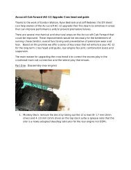
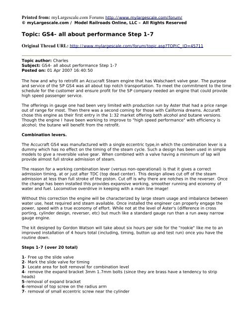
The how and why to retrofit an Accucraft Steam engine that has Walschaert valve gear. The purpose<br />
and service of the SP <strong>GS4</strong> was <strong>all</strong> <strong>about</strong> top notch transportation. To meet the commitment to the time<br />
schedule for the customer and ensure profit for the SP company needed an engine that could provide<br />
high speed passenger service.<br />
The offerings in gauge one had been very limited with production run by Aster that had a price range<br />
out of range for most. Then there was a second coming for those with California dreams. Accuraft<br />
chose this engine as their first entry in the 1:32 market offering both alcohol and butane versions.<br />
Though the engine I have been working to improve to "high speed <strong>performance</strong>" with efficiency is<br />
alcohol; the butane will benefit from the retrofit.<br />
Combination levers.<br />
The Accucraft <strong>GS4</strong> was manufactured with a single eccentric type,in which the combination lever is a<br />
dummy which has no effect on the timing of the steam cycle. Such a design has been used in simple<br />
models to give a reversible valve gear. When combined with a valve having a minimum of lap will<br />
provide almost full stroke admission of steam.<br />
The reason for a working combination lever (versus non-operational) is that it gives a correct<br />
admission timing, at or just after TDC (top dead center). This design <strong>all</strong>ows cut off of the steam<br />
admission at less than full stroke of the piston. Cut off is why there are notches in the reverser. Once<br />
the change has been inst<strong>all</strong>ed this provides expansive working, smoother running and economy of<br />
water and fuel. Locomotive overdrive in keeping with a main line image!<br />
Without this correction the engine will be characterized by large steam usage and imbalance between<br />
water use, heat required and steam available. Once inst<strong>all</strong>ed the engineer can properly engage the<br />
power, speed with a true economy of effort. While not at the level of Aster's (difference in cross<br />
porting, cylinder design, reverser, etc) but much like a standard gauge run than a run away narrow<br />
gauge engine.<br />
The kit designed by Gordon Watson will take <strong>about</strong> six hours per side for the "rookie" like me to an<br />
improved inst<strong>all</strong>ation of 4 hours total (including, timing, button up and test run) once you have the<br />
routine down.<br />
<strong>Step</strong>s 1-7 (over 20 total)<br />
1- Free up the slide valve<br />
2- Mark the slide valve for timing<br />
3- Locate area for bolt removal for combination level<br />
4- remove the expand bracket 3mm 1.7mm bolts (since they are brass have a tendency to strip<br />
heads)<br />
5-removal of expand bracket<br />
6-removal of top screw on the radius arm<br />
7- removal of sm<strong>all</strong> eccentric screw near the cylinder
#1<br />
#2
#3<br />
#4
#5 #6<br />
#7
So far, easy- well life is not always so in any task as one will appreciate performs once one has done<br />
this job (along with admire Gordon for his skills)!
<strong>GS4</strong>- Performance <strong>Step</strong> 8-12<br />
Original Thread URL: http://www.mylargescale.com/forum/topic.asp?TOPIC_ID=45722<br />
Topic author: Charles<br />
Subject: <strong>GS4</strong>- Performance <strong>Step</strong> 8-12<br />
Posted on: 02 Apr 2007 05:25:20<br />
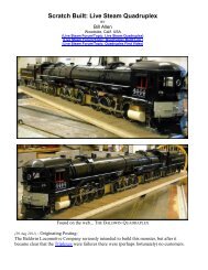
The power and speed of the <strong>GS4</strong> design can be denoted in the route and consist of coaches on most<br />
runs. The powerful Northern locomotive could cruise at 70 miles per hour and haul a 14 car train<br />
unassisted up a 2.2% grade through the mountains.<br />
8- remove the sm<strong>all</strong> screw on combination lever near piston<br />
9- combination lever and <strong>all</strong> parts loose pull out valve block<br />
10- Careful removal as valve block is now showing (good to note here the orientation mark up arrow<br />
since it has worn in a particular way)<br />
11- Complete unit is out ready for disassembly<br />
12- Punch out with blunt object(we acut<strong>all</strong>y did the job with a sm<strong>all</strong> screwdriver) the pin holding parts<br />
together ***this can be time consuming and one of those moments when you begin to have second<br />
thoughts. In particular if the alignment of the holes for the pin are off just a bit or were drill somewhat<br />
sm<strong>all</strong>er or just stubborn. Could be a session when the basic vocabulary (#!?>^~) of four letter words<br />
may not describe the job at hand but you "swear" it helped get the pin out! One of the three jobs we<br />
have done took the major portion of a morning.<br />
12a- (sorry <strong>about</strong> mislabel) main parts disassembled<br />
#8
#9<br />
#10
#11<br />
#12
#12a<br />
Note the lever in the forefront next to the pin. Top only has one hole in it. This will be a point of<br />
change with the new parts
<strong>GS4</strong> Performance 13-18<br />
Original Thread URL: http://www.mylargescale.com/forum/topic.asp?TOPIC_ID=45738<br />
Topic author: Charles<br />
Subject: <strong>GS4</strong> Performance 13-18<br />
Posted on: 03 Apr 2007 05:40:03<br />
This is where you ensure that the movement will <strong>all</strong>ow the maximum range of motion for the operation<br />
of the combination lever related to the reverser and cut off.<br />
You can see the change in the new part from Gordon in have two top holes in the lever (laying down<br />
on the cutting board near 2.5 mark).<br />
Filing is the skill at hand to complete this portion, in particular photo #14 and #16 show the groove<br />
that must be made to ensure proper motion.<br />
13- measurement for throw to and from same amount both directions (2mm)<br />
14- file forward and back on top of yolk for clear by the top pin (from flat to two grooves)<br />
15-file inside the yolk for clearance<br />
16- finish filing on top of yolk<br />
17- check of big pin for clearance on top of yolk<br />
18- checking motion forward and back<br />
#13
#14<br />
#15
#16<br />
#17
#18<br />
Also, note that prior to re-inst<strong>all</strong>ing there are two bolt heads on the cross head that need to be filed to<br />
increase space for travel. On original setup this was compensated for by bending the rod.<br />
Note in photo #8 in prior steps the two bolt head on cross head guide behind the combination lever<br />
have been filed down.
<strong>GS4</strong> Performance 19-21 Side #1<br />
Original Thread URL: http://www.mylargescale.com/forum/topic.asp?TOPIC_ID=45756<br />
Topic author: Charles<br />
Subject: <strong>GS4</strong> Performance 19-21 Side #1<br />
Posted on: 04 Apr 2007 05:18:51<br />
The retrofit to improve <strong>performance</strong> is <strong>about</strong> 1/3 finished<br />
19- file inside the valve block and check the components for fit.<br />
20-reassemble the main components of combination lever check clearance by the "big pin" on the top<br />
regards the swing of the combination lever.<br />
21-realign unit into the valve chest. Might need some filing of the body channel on the frame<br />
(particularly if you did not note the position of the valve block coming out of the assembly)or rotate for<br />
smooth movement as necessary. Check the movement of combination lever relative to the cross head<br />
guides for clearance<br />
Besides doing the other side, two other aspects will be covered:<br />
1) Smokebox components<br />
2) Timing<br />
#19
#20<br />
#21
<strong>GS4</strong> Performance 22-27<br />
Original Thread URL: http://www.mylargescale.com/forum/topic.asp?TOPIC_ID=45773<br />
Printed on: 25 Apr 2007<br />
Topic author: Charles<br />
Subject: <strong>GS4</strong> Performance 22-27<br />
Posted on: 05 Apr 2007 04:48:44<br />
The valve chest and attachment of the motion gear are the areas to be completed.<br />
22- Attaching the radius arm, the union link, valve stem and the slide valve<br />
23- Alignment of the slide valve<br />
24- Repeat #1-23 for the other side<br />
25- Once <strong>all</strong> of this is finished for both sides then time the engine<br />
26- Smokebox components: Blower and exhaust nozzles inst<strong>all</strong>ed<br />
27- This retrofit along with proper wicks and a better baffle will <strong>all</strong>ow for improvement and efficiency<br />
of your engine. Combine the baffle with a collar on the larger flue will direct the heat properly from the<br />
firebox through the boiler.<br />
#22
#23<br />
#25
#26<br />
http://home.new.rr.com/trumpetb/loco/wdiagram.html
27<br />
BTW- Most will have denote the top of the smokebox prior to baffle inst<strong>all</strong>ation. The original engine<br />
had no baffle,(most with inefficient baffles) and the result is extreme heat/fires in smokebox.<br />
The baffle design with holes are not necessary just my theory regards heat transfer to lower flues<br />
relative to space with the baffle in place. The concept of a baffle firebox length at a set angle is based<br />
on established fundamentals with brick arches.<br />
Performance test run:<br />
http://www.mylargescale.com/forum/topic.asp?TOPIC_ID=45456<br />
Replies:<br />
Reply author: Charles<br />
Replied on: 13 Apr 2007 17:40:32<br />
Today was not ideal for a run relative to the weather: mid-40's, windy- 30 MPH, cloudy but it was the<br />
opportunity we had to test run 2 upgraded <strong>GS4</strong>. The <strong>performance</strong> checks on both engines were very<br />
satisfying. Combination of power, speed and economy have been established. Our next opportunity is<br />
to do some actual data collection. Both runs(at moderate speed in case the wind blow over the rake of<br />
cars) today were <strong>about</strong> 30 minutes including firing with one tank of fuel, water with the ability to run<br />
longer but lunch and the bitter cold wind made for only rationale to leave a <strong>GS4</strong> static on the rails!<br />
http://1stclass.mylargescale.com/Ryan/GS-4/GS-4%20demo.MPG<br />
1- (Video) is the Stage 4 with a set up similar to Aster <strong>GS4</strong> (cross porting, comb lever, etc)<br />
2- The stage 3 setup that tops off with the combination lever action (ran beautifully)
Reply author: Charles<br />
Replied on: 25 Apr 2007 04:40:02<br />
Just a finishing point as to the conversions showing <strong>performance</strong> runs for the Gordon Watson over<strong>all</strong><br />
which includes: working combination lever, cross porting, screw reverser, enlarging the steam pipes to<br />
cylinder, redesign water delivery system (axle, hand pump), new clack/check valve, new sight glass,<br />
new exhaust/blower, reworked rods and much more.<br />
http://1stclass.mylargescale.com/Ryan/PLS%2007%20meets/MOV00111.MPG<br />
Running with some classic Asters:<br />
http://1stclass.mylargescale.com/Ryan/PLS%2007%20meets/MOV00112.MPG<br />
Reply author: David Rose<br />
Replied on: 25 Apr 2007 06:25:48<br />
quote:<br />
Origin<strong>all</strong>y posted by Charles<br />
....redesign water delivery system (axle, hand pump), new clack/check valve...<br />
Charles,<br />
Does this engine use the same hand pump and check valve as the K-28. Did you cover the redesign in<br />
one of your <strong>GS4</strong> topics?<br />
Reply author: Charles<br />
Replied on: 25 Apr 2007 07:30:48<br />
Dave<br />
Origin<strong>all</strong>y, the system in the <strong>GS4</strong> was basic<strong>all</strong>y the same as the K28. We have redesigned in the <strong>GS4</strong><br />
engines using clack valves with b<strong>all</strong>s, get rid of the valve system that is stock from Accucraft and new hand<br />
pump.<br />
Here is Gordon Watson's overview and fix to stock unit:<br />
axle feed pump didnt work! the valves in it are spring loaded with O ring seats.. thats fine on the delivery<br />
side. We have to remember that the suction side can only ever have 14PSI unloading the valve and the area<br />
of our valve seats is very sm<strong>all</strong>, so spring loading inlet side valves doesnt work! I counter bored the inlet<br />
banjo bolt to provide a seating for a b<strong>all</strong> valve and inst<strong>all</strong>ed a sm<strong>all</strong> scewed sleeve up inside the pump body.<br />
to provide a lift limiter.the pump then worked fine and kept up with the boiler demand.<br />
Printed from: myLargescale.com Forums http://www.mylargescale.com/forum/<br />
© myLargescale.com / Model Railroads Online, LLC – All Rights Reserved