SANMOTION Q - Sanyo Denki America, Inc.
SANMOTION Q - Sanyo Denki America, Inc.
SANMOTION Q - Sanyo Denki America, Inc.

You also want an ePaper? Increase the reach of your titles
YUMPU automatically turns print PDFs into web optimized ePapers that Google loves.
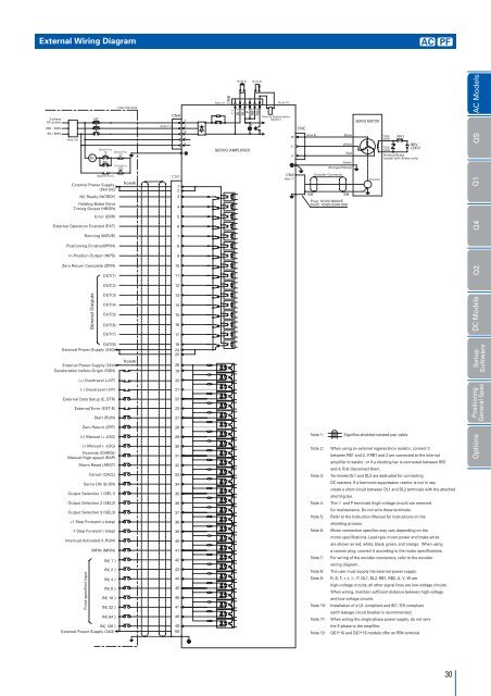
External Wiring Diagram<br />
AC PF<br />
3-phase<br />
AC power<br />
200 - 230V<br />
5060Hz<br />
Note 10)<br />
MC<br />
MC<br />
<br />
<br />
MC<br />
System Error<br />
External Power Supply<br />
(24V DC)<br />
NC Ready (NCRDY)<br />
Holding Brake Drive<br />
Timing Output (HBON)<br />
User Devices<br />
<br />
<br />
<br />
<br />
Note8)<br />
Note 11)<br />
CNA<br />
<br />
1<br />
2<br />
3<br />
4<br />
<br />
<br />
<br />
<br />
<br />
Note 4)<br />
CNB<br />
(-)<br />
DL1<br />
DL2<br />
Note 3) Note 2)<br />
P<br />
SERVO AMPLIFIER<br />
RB1<br />
RB2<br />
<br />
Note 12)<br />
Internal Regeneration<br />
Resistor<br />
<br />
<br />
<br />
CN2<br />
Note 7)<br />
CNC<br />
Note 6)<br />
Black<br />
White<br />
Red<br />
Green<br />
(Orange/Yellow)<br />
Encoder Connector<br />
SH<br />
SH<br />
Plug: 10120-3000VE.<br />
Shell: 10320-52A0-008<br />
SERVO MOTOR<br />
Encoder<br />
Orange<br />
(yellow)<br />
Orange<br />
(yellow)<br />
RY1<br />
90V<br />
(24V)<br />
Holding Brake<br />
(install with Brake only)<br />
Q1 QS AC Models<br />
Error (ERR)<br />
5<br />
External Operation Enabled (EXT)<br />
Running (MOVE)<br />
Positioning Finished(PFIN)<br />
In-Position Output (INPS)<br />
Zero Return Complete (ZFIN)<br />
OUT1<br />
OUT2<br />
OUT3<br />
OUT4<br />
OUT5<br />
OUT6<br />
OUT7<br />
OUT8<br />
External Power Supply (24G)<br />
External Power Supply (24V)<br />
Deceleration before Origin (SDN)<br />
(+) Overtravel (+OT)<br />
(-) Overtravel (-OT)<br />
External Data Setup (E_STR)<br />
External Error (EXT-E)<br />
Start (RUN)<br />
Zero Return (ZRT)<br />
(+) Manual (+ JOG)<br />
(-) Manual (- JOG)<br />
Override (OVRID)/<br />
Manual High-speed (RAP)<br />
Alarm Reset (ARST)<br />
Cancel (CACL)<br />
Servo ON (S-ON)<br />
Output Selection 1 (SEL1)<br />
Output Selection 2 (SEL2)<br />
Output Selection 3 (SEL3)<br />
+1 Step Forward (+lstep)<br />
-1 Step Forward (-lstep)<br />
Interrupt Activated (I_RUN)<br />
MFIN (MFIN)<br />
Point-specified Input<br />
General Outputs<br />
IN1 <br />
IN2 <br />
IN4 <br />
IN8 <br />
IN16 <br />
IN32 <br />
IN64 <br />
IN128 <br />
External Power Supply (24G)<br />
Note8)<br />
6<br />
7<br />
8<br />
9<br />
10<br />
11<br />
12<br />
13<br />
14<br />
15<br />
16<br />
17<br />
18<br />
24<br />
25<br />
26<br />
19<br />
20<br />
21<br />
22<br />
23<br />
27<br />
28<br />
29<br />
30<br />
31<br />
32<br />
33<br />
34<br />
35<br />
36<br />
37<br />
38<br />
39<br />
40<br />
41<br />
42<br />
43<br />
44<br />
45<br />
46<br />
47<br />
48<br />
49<br />
50<br />
Note 1:<br />
Note 2:<br />
Note 3:<br />
Note 4:<br />
Note 5:<br />
Note 6:<br />
Note 7:<br />
Note 8:<br />
Note 9:<br />
Note 10:<br />
Note 11:<br />
Note 12:<br />
Signifies shielded twisted-pair cable.<br />
When using an external regeneration resistor, connect it<br />
between RB1 and 2. If RB1 and 2 are connected to the internal<br />
amplifier’s resistor, or if a shorting bar is connected between RB1<br />
and 4, first disconnect them.<br />
Terminals DL1 and DL2 are dedicated for connecting<br />
DC reactors. If a harmonic suppression reactor is not in use,<br />
create a short circuit between DL1 and DL2 terminals with the attached<br />
shorting bar.<br />
The and P terminals (high-voltage circuit) are reserved<br />
for maintenance. Do not wire these terminals.<br />
Refer to the Instruction Manual for instructions on the<br />
shielding process.<br />
Motor connection specifics may vary depending on the<br />
motor specifications. Lead-type motor power and brake wires<br />
are shown as red, white, black, green, and orange. When using<br />
a cannon plug, connect it according to the motor specifications.<br />
For wiring of the encoder connectors, refer to the encoder<br />
wiring diagram.<br />
The user must supply the external power supply.<br />
R, S, T, r, t, , P, DL1, DL2, RB1, RB2, U, V, W are<br />
high-voltage circuits; all other signal lines are low-voltage circuits.<br />
When wiring, maintain sufficient distance between high-voltage<br />
and low-voltage circuits.<br />
Installation of a UL compliant and IEC / EN compliant<br />
earth leakage circuit breaker is recommended.<br />
When wiring the single-phase power supply, do not wire<br />
the S-phase to the amplifier.<br />
QS1*10 and QS1*15 models offer an RB4 terminal.<br />
Options DC Models Q2 Q4<br />
Setup<br />
Software<br />
Positionng<br />
General Spec<br />
30