LEP 5.1.12 -00 Electron spin resonance
LEP 5.1.12 -00 Electron spin resonance
LEP 5.1.12 -00 Electron spin resonance

Create successful ePaper yourself
Turn your PDF publications into a flip-book with our unique Google optimized e-Paper software.
<strong>Electron</strong> <strong>spin</strong> <strong>resonance</strong><br />
<strong>LEP</strong><br />
<strong>5.1.12</strong><br />
-<strong>00</strong><br />
Related topics<br />
Zeeman effect, energy quantum, quantum number, <strong>resonance</strong>,<br />
g-factor, Landé factor.<br />
Principle<br />
The g-factor of a DPPH (Diphenylpikrylhydrazyl) and the halfwidth<br />
of the absorption line are determined, using the ESR<br />
apparatus.<br />
Equipment<br />
ESR resonator with field coils 09050.<strong>00</strong> 1<br />
ESR power supply 09050.93 1<br />
Power supply, universal 135<strong>00</strong>.93 1<br />
Oscilloscope, 30 MHz, 2 channels 11459.95 1<br />
Digital multimeter 07134.<strong>00</strong> 1<br />
Screened cable, BNC, l = 750 mm 07542.11 4<br />
Adapter, BNC-socket/4 mm plug pair 07542.27 1<br />
Connecting cord, l = 5<strong>00</strong> mm, blue 07361.04 3<br />
Connecting cord, l = 5<strong>00</strong> mm, red 07361.01 2<br />
Connecting cord, l = 5<strong>00</strong> mm, yellow 07361.02 2<br />
Options:<br />
Teslameter, digital 13610.93 1<br />
Hall probe, tangent., prot. cap 13610.02 1<br />
Tasks<br />
With ESR on a DPPH specimen determination of<br />
1. the g-factor of the free electron, and<br />
2. the half-width of the absorption line.<br />
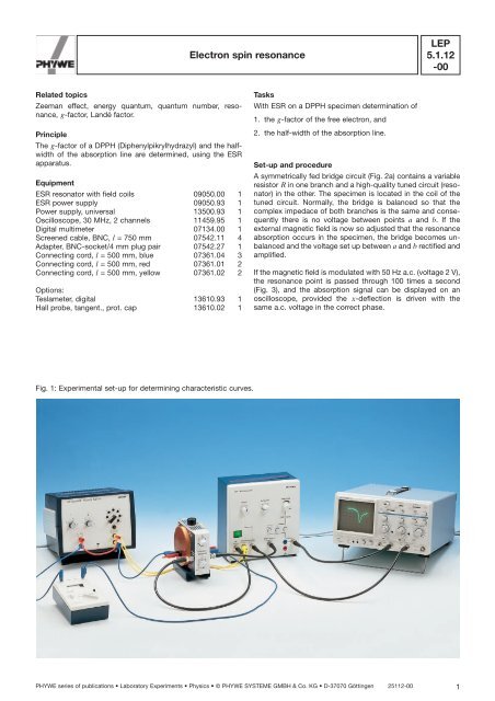
Set-up and procedure<br />
A symmetrically fed bridge circuit (Fig. 2a) contains a variable<br />
resistor R in one branch and a high-quality tuned circuit (resonator)<br />
in the other. The specimen is located in the coil of the<br />
tuned circuit. Normally, the bridge is balanced so that the<br />
complex impedace of both branches is the same and consequently<br />
there is no voltage between points a and b. If the<br />
external magnetic field is now so adjusted that the <strong>resonance</strong><br />
absorption occurs in the specimen, the bridge becomes unbalanced<br />
and the voltage set up between a and b rectified and<br />
amplified.<br />
If the magnetic field is modulated with 50 Hz a.c. (voltage 2 V),<br />
the <strong>resonance</strong> point is passed through 1<strong>00</strong> times a second<br />
(Fig. 3), and the absorption signal can be displayed on an<br />
oscilloscope, provided the x-deflection is driven with the<br />
same a.c. voltage in the correct phase.<br />
Fig. 1: Experimental set-up for determining characteristic curves.<br />
PHYWE series of publications • Laboratory Experiments • Physics • © PHYWE SYSTEME GMBH & Co. KG • D-37070 Göttingen 25112-<strong>00</strong> 1
<strong>LEP</strong><br />
<strong>5.1.12</strong><br />
-<strong>00</strong><br />
<strong>Electron</strong> <strong>spin</strong> <strong>resonance</strong><br />
Fig. 2a: Measuring bridge of the ESR apparatus.<br />
Fig. 3: The magnetic field B is compounded from a d.c. field<br />
B = and an alternating field B , so that B = B = + B .<br />
Through l = , B = is to be adjusted so that B = = B r .<br />
Fig. 2b: Wiring diagram.<br />
First, the bridge has to be balanced. In doing this (without<br />
external magnetic field), “R” on the resonator is brought to its<br />
central position and “C” to the lefthand stop. On the ESR<br />
power supply, key 8 “bridge balancing” (see operating instructions)<br />
is pressed, the oscilloscope input is switched to d.c.<br />
and 1 V/cm and the line is brought to the zero with 12 “Zero”<br />
(beforehand bring to zero with “Position” in GND setting). For<br />
the wiring see Fig. 2b and operating instructions.<br />
Now the absoption signal can be searched for: the coil current<br />
is set to about 1.3 A, button 10 “” pressed and the zero line<br />
again brought to the centre with 12. The signal can now be<br />
sought with 25 “C”, while continuously correcting the zero<br />
point with 12.<br />
As soon as a signal appears, both lines are made to coincide<br />
with 13 “Phase”. As long as the <strong>resonance</strong> frequency of the<br />
tuned circuit does not correspond to the oscillator frequency,<br />
the signal appears asymmetrical or as a derivative. The resonator<br />
should thus be tuned with 25 “C” until a symmetrical<br />
absorption signal of maximum amplitude appears on the<br />
oscilloscope. The sensitivity of the oscilloscope is increased<br />
so that the signal reaches a height of 8-10 cm. By varying the<br />
d.c. current in the coil, the signal can be brought to the centre<br />
of the screen, so that the minimum is on the y-axis, (correct<br />
again with 13 “Phase” if necessary). The <strong>resonance</strong> magnetic<br />
field B r can be calculated from the d.c. current l res now flowing.<br />
If the signal is now adjusted so that the x-axis goes exactly<br />
half way through the height of the signal, then, once the alter-<br />
2<br />
25112-<strong>00</strong> PHYWE series of publications • Laboratory Experiments • Physics • © PHYWE SYSTEME GMBH & Co. KG • D-37070 Göttingen
1 S2 p m B 2 S · S B 2 p 1 ec 1 (1)<br />
m j = j, j – 1, … –j.<br />
<strong>LEP</strong><br />
<strong>Electron</strong> <strong>spin</strong> <strong>resonance</strong><br />
<strong>5.1.12</strong><br />
-<strong>00</strong><br />
nating voltage modulation has been switched off, the two current<br />
In this case, H Z (2) can be written<br />
values at which the moving spot crosses the x-axis can<br />
be determined by slowly varying the d.c. current in the coil.<br />
The half-width of the signal is calculated from the difference<br />
H Z = m B g j B · J (3)<br />
between these currents.<br />
with the Landé factor<br />
J 1J 12 S 1S 12 L 1L 12<br />
g j 1 <br />
Theory and evaluation<br />
2J 1J 12<br />
. (4)<br />
If an electron of mass m and charge e is located in an electromagnetic<br />
field with vector potential A and scalar potential f, Disregarding the influence of the nuclear <strong>spin</strong>, the energy<br />
then its steady-state energy level and characteristic states are levels of H Z , for magnetic fields in the Z-direction, are<br />
given by the solutions of the Dirac equation.<br />
If the equation is solved for the c, component of the sate <strong>spin</strong>or,<br />
E Z = m B g j Bm j<br />
it reads:<br />
with<br />
where<br />
m B <br />
eh (Bohr Magneton)<br />
2mc<br />
= 9.27 · 10 –27 Am 2<br />
pS p S e>c A<br />
S<br />
The selection rule for magnetic transitions of the electron <strong>spin</strong><br />
<strong>resonance</strong> experiment is<br />
m j = ±1<br />
so that the absorption condition reads<br />
m B g j B = E = hf.<br />
where p is the momentum, c the velocity of light, S the electron<br />
<strong>spin</strong> operator, and B = rot A is the magnetic field.<br />
h is Planck’s constant<br />
and<br />
h = 6.626 · 10 –34 Js,<br />
e 1 2 11 1E>mc2 22 1E mc 2 2<br />
is approximately the excess of energy over the residual mass<br />
energy.<br />
For a free electron in a uniform magnetic field, the second<br />
term (Zeeman term) interchanges with the first in the<br />
Hamiltonian operator of (1), and the energy level<br />
e = e o + m B 2S z B z ,<br />
is obtained<br />
if the z-axis lies in the direction of the magnetic field.<br />
e o is the energy of the electron without a magnetic field.<br />
If the diamagnetic contribution from the first term of (1) is disregarded<br />
in the general case, then for the electron in a uniform<br />
magnetic field, the interaction Hamiltonian operator with the<br />
magnetic filed, (Zeeman effect) is<br />
H Z = m B B · ( L + 2S ), (2)<br />
where L and S are the operators of the orbital and <strong>spin</strong> angular<br />
momentum respectively. In addition, the <strong>spin</strong>orbit interaction<br />
H so = l · S · L <br />
should be taken into account, so that only the total angular<br />
momentum<br />
J = L + S <br />
is a conservation value.<br />
In many cases, especially with molecular radicals, the angular<br />
momentum L of the unpaired electron is extinguished by the<br />
electric fields of the neighbouring atoms and molecules. In the<br />
case of DPPH, L = 0 and therefore<br />
g j = 2.<br />
In (3),<br />
<br />
m = mB · g j · J (5)<br />
is the magnetic moment of an electron with the angular<br />
momentum J in units of the Bohr magneton m B .<br />
If account is also taken of the exchange of virtual photons between<br />
the electron and a radiation field in the static limit<br />
through inclusion of the vertex corrections in increasing order,<br />
a modified abnormal magnetic moment of the electron is<br />
obtained as a series in the fine-structure constant a:<br />
e2<br />
a <br />
h · c<br />
S<br />
m mB a 1 a a2<br />
0.328<br />
2p p ... b g S<br />
2 j J<br />
The correction factor in the parentheses of equation (6) is<br />
generally taken into account in g j , so that g j then 2.<br />
Fig. 4 shows the energy level in the magnetic field B, for<br />
DPPH.<br />
By supplying the corresponding energy, transitions can be<br />
induced between the levels:<br />
hf = g j mBH.<br />
The probability of transtion depends on the occupation number<br />
and on the transition matrix elements. The latter are the<br />
same for absorption and emission processes.<br />
Because of the interactions of the <strong>spin</strong>s with the lattice or with<br />
one another, the levels are not sharply defined, and this leads<br />
(6)<br />
PHYWE series of publications • Laboratory Experiments • Physics • © PHYWE SYSTEME GMBH & Co. KG • D-37070 Göttingen 25112-<strong>00</strong> 3
<strong>LEP</strong><br />
<strong>5.1.12</strong><br />
-<strong>00</strong><br />
<strong>Electron</strong> <strong>spin</strong> <strong>resonance</strong><br />
to a line width of the absorption spectrum and prevents an<br />
equipartition of the levels (saturation) because of the corresponding<br />
relaxation processes.<br />
The occupation numbers are given in accordance with the<br />
Boltzmann relation by:<br />
N 2<br />
N 1<br />
e ¢E<br />
kT e gjm B B<br />
kT ,<br />
where k is the Boltzmann constant. It is customary to take<br />
account of other interactions in the constant g which vary<br />
linearly B, e.g. the contact of Fermi interaction (WW) with the<br />
nucleus, i.e.<br />
g = g j (1 + WW),<br />
where g is specific for the measured substance and f is predetermined<br />
at 146 MHz by the apparatus, so that B must be<br />
varied to satisfy the <strong>resonance</strong> condition.<br />
For the magnetic field of a Helmholtz arrangement with w =<br />
241 turns, current I and radius R = 0.048 m,<br />
For the g-factor, one obtains:<br />
or<br />
g = 10.43 ·<br />
g = 2.507 ·<br />
with the stated values.<br />
; B r in teslas<br />
in amperes,<br />
A <strong>resonance</strong> current of 1.245 A was measured, corresponding<br />
to a g-factor of 2.02, and a half-width value of 2.7 · 10 –4 T.<br />
(Literature values for DPPH:<br />
g = 2.<strong>00</strong>37, half-width 2.8 · 10 –4 T).<br />
1<br />
B r<br />
1<br />
I r<br />
; I r<br />
Note<br />
The analyzed specimen DPPH (Diphenylpicrylhydrazyl) is a<br />
organic, paramagnetic material with one stable radical. The<br />
magnetic moment of the molecul is determined only by the<br />
<strong>spin</strong> moment of the valence in the “N”-bridge.<br />
w · I<br />
B = 0.6445 · m o ·<br />
R<br />
on the axis of symmetry between the coils, where<br />
m o = 1.256 · 10 –6 T · m ·<br />
A<br />
With the numerical values stated, one obtains<br />
B = 4.0642 · 10 –3 T · i .<br />
A<br />
4<br />
25112-<strong>00</strong> PHYWE series of publications • Laboratory Experiments • Physics • © PHYWE SYSTEME GMBH & Co. KG • D-37070 Göttingen
<strong>Electron</strong> <strong>spin</strong> <strong>resonance</strong><br />
<strong>LEP</strong><br />
<strong>5.1.12</strong><br />
-<strong>00</strong><br />
<strong>Electron</strong> <strong>spin</strong> <strong>resonance</strong> (ESR), model experiment<br />
Model experiment for electron <strong>spin</strong> <strong>resonance</strong> for clear<br />
demonstration of interaction between the magnetic moment<br />
of the electron <strong>spin</strong> with a superimposed direct or alternating<br />
magnetic field.<br />
A ball with a central rod magnet, which rotates with low friction<br />
on an air cushion, acts as model electron. Two pairs of<br />
coils allow to generate a direct magnetic field B o and an alternating<br />
magnetic field B 1 . The axes of both fields intersect perpendicularly<br />
at the centre of the ball.<br />
The table is slightly inclined to start the electron gyroscope<br />
with an air draught (Magnus effect). If the direct magnetic field<br />
B o acts on the ball, a precession of the magnet axis is observed.<br />
Precession frequency increases with the intensity of field<br />
B o .<br />
With a second pair of coils and a pole changeover switch<br />
(commutator), a supplementary alternating field B 1 is generated.<br />
If the change of poles occurs at the right phase, the angle<br />
between the gyroscope axis and the direction of the direct<br />
field is continuously increased, until the magnetic axis of the<br />
ball is opposed to the field direction (<strong>spin</strong> flip).<br />
Ask for a complete equipment list Exp.no. P1298<strong>00</strong>0<br />
Material<br />
Gyroscope w. magnetic axis, ESR model 11208.<strong>00</strong> 1<br />
Coil 12<strong>00</strong> turns 06515.01 4<br />
Iron core, short, laminated 065<strong>00</strong>.<strong>00</strong> 2<br />
Commutator switch 06034.03 1<br />
On/off switch 06034.01 1<br />
Blower 13770.93 1<br />
Pressure tube with end piece 1.5 m 11205.01 1<br />
Variable transformer with rectifier<br />
25 V~/20 V–, 12 A 13531.93 1<br />
Connecting cable 8<br />
Fig. 4: <strong>Electron</strong> <strong>spin</strong> <strong>resonance</strong> (ESR), model experiment.<br />
PHYWE series of publications • Laboratory Experiments • Physics • © PHYWE SYSTEME GMBH & Co. KG • D-37070 Göttingen 25112-<strong>00</strong> 5
<strong>LEP</strong><br />
<strong>5.1.12</strong><br />
-<strong>00</strong><br />
<strong>Electron</strong> <strong>spin</strong> <strong>resonance</strong><br />
6<br />
25112-<strong>00</strong> PHYWE series of publications • Laboratory Experiments • Physics • © PHYWE SYSTEME GMBH & Co. KG • D-37070 Göttingen