USB / S / RE - Seattle Coffee Gear
USB / S / RE - Seattle Coffee Gear
USB / S / RE - Seattle Coffee Gear

Create successful ePaper yourself
Turn your PDF publications into a flip-book with our unique Google optimized e-Paper software.
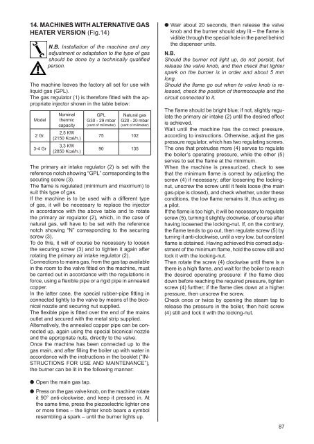
14. MACHINES WITH ALTERNATIVE GAS<br />
HEATER VERSION (Fig.14)<br />
N.B. Installation of the machine and any<br />
adjustment or adaptation to the type of gas<br />
should be done by a technically qualified<br />
person.<br />
The machine leaves the factory all set for use with<br />
liquid gas (GPL).<br />
The gas regulator (1) is therefore fitted with the appropriate<br />
injector shown in the table below:<br />
Model<br />
2 Gr.<br />
3-4 Gr<br />
Nominal<br />
thermic<br />
capacity<br />
2,5 KW<br />
(2150 Kcal/h.)<br />
3,3 KW<br />
(2850 Kcal/h.)<br />
The primary air intake regulator (2) is set with the<br />
reference notch showing “GPL” corresponding te the<br />
secuting screw (3).<br />
The flame is regulated (minimum and maximum) to<br />
suit this type of gas.<br />
If the machine is to be used with a different type<br />
of gas, it will be necessary to replace the injector<br />
in accordance with the above table and to rotate<br />
the primary air regulator (2), which, in the case of<br />
natural gas, will have to be set with the reference<br />
notch showing “N” corresponding to the securing<br />
screw (3).<br />
To do this, it will of course be necessary to loosen<br />
the securing screw (3) and to tighten it again after<br />
rotating the primary air intake regulator (2).<br />
Connections to mains gas, from the gas tap available<br />
in the room to the valve fitted on the machine, must<br />
be carried out in accordance with the regulations in<br />
force, using a flexible pipe or a rigid pipe in annealed<br />
copper.<br />
In the latter case, the special rubber-pipe fitting in<br />
connected tightly to the valve by means of the biconical<br />
nozzle and securing nut supplied.<br />
The flexible pipe is fitted over the end of the mains<br />
outlet and secured with the metal strip supplied.<br />
Alternatively, the annealed copper pipe can be connected<br />
up, again using the special biconical nozzle<br />
and the appropriate nuts, directly to the valve.<br />
Once the machine has been connected up to the<br />
gas main, and after filling the boiler up with water in<br />
accordance with the instructions in the booklet (“IN-<br />
STRUCTIONS FOR USE AND MAINTENANCE”),<br />
the burner can be lit in the following manner:<br />
Open the main gas tap.<br />
GPL<br />
G30 - 29 mbar<br />
(cent of milimeter)<br />
Natural gas<br />
G20 - 20 mbar<br />
(cent of milimeter)<br />
75 102<br />
90 135<br />
Press on the gas valve knob, on the machine rotate<br />
it 90° anti-clockwise, and keep it pressed in. At<br />
the same time, press the piezoelectric lighter one<br />
or more times – the lighter knob bears a symbol<br />
resembling a spark – until the burner lights up.<br />
Wair about 20 seconds, then release the valve<br />
knob and the burner should stay lit – the flame is<br />
vidible through the special hole in the panel behind<br />
the dispenser units.<br />
N.B.<br />
Should the burner not light up, do not persist, but<br />
release the valve knob, and then check that lighter<br />
spark on the burner is in order and about 5 mm<br />
long.<br />
Should the flame go out when te valve knob is released,<br />
check the position of thermocouple and the<br />
circuit connected to it.<br />
The flame should be bright blue; if not, slightly regulate<br />
the primary air intake (2) until the desired effect<br />
is achieved.<br />
Wait until the machine has the correct pressure,<br />
according to instructions. Otherwise, adjust the gas<br />
pressure regulator, which has two regulating screws.<br />
The one that protrudes more (4) serves to regulate<br />
the boiler’s operating pressure, while the other (5)<br />
serves to set the flame at the minimum.<br />
When the machine is pressurized, check to see<br />
that the minimum flame is correct by adjusting the<br />
screw (4) if necessary; after loosening the lockingnut,<br />
unscrew the screw until it feels loose (the main<br />
gas-pipe is closed), and check whether, under these<br />
conditions, the low flame remains lit, thus acting as<br />
a pilot.<br />
If the flame is too high, it will be necessary to regulate<br />
screw (5), turning it slightly clockwise, of course after<br />
having loosened the locking-nut. If, on the contrary,<br />
the flame tends to go out, then regulate screw (5) by<br />
turning it anti-clockwise, until a very low, but constant<br />
flame is obtained. Having achieved this correct adjustment<br />
of the minimum flame, hold the screw still and<br />
lock it with the locking-nut.<br />
Then rotate the screw (4) clockwise until there is a<br />
there is a high flame, and wait for the boiler to reach<br />
the desired operating pressure: if the flame dies<br />
down before reaching the required pressure, tighten<br />
screw (4) further; if the flame dies down at a higher<br />
pressure, then unscrew the screw.<br />
Check once or twice by opening the steam tap to<br />
release the pressure in the boiler, then hold screw<br />
(4) still and lock it with the locking-nut.<br />
87