D a t a S h e e t - SemiconductorStore.com
D a t a S h e e t - SemiconductorStore.com
D a t a S h e e t - SemiconductorStore.com

You also want an ePaper? Increase the reach of your titles
YUMPU automatically turns print PDFs into web optimized ePapers that Google loves.
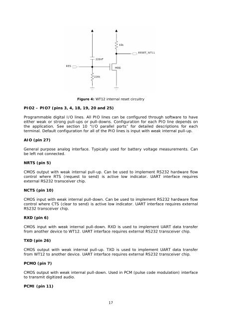
Figure 4: WT12 internal reset circuitry<br />
PIO2 – PIO7 (pins 3, 4, 18, 19, 20 and 25)<br />
Programmable digital I/O lines. All PIO lines can be configured through software to have<br />
either weak or strong pull-ups or pull-downs. Configuration for each PIO line depends on<br />
the application. See section 10 “I/O parallel ports” for detailed descriptions for each<br />
terminal. Default configuration for all of the PIO lines is input with weak internal pull-up.<br />
AIO (pin 27)<br />
General purpose analog interface. Typically used for battery voltage measurements. Can<br />
be left not connected.<br />
NRTS (pin 5)<br />
CMOS output with weak internal pull-up. Can be used to implement RS232 hardware flow<br />
control where RTS (request to send) is active low indicator. UART interface requires<br />
external RS232 transceiver chip.<br />
NCTS (pin 10)<br />
CMOS input with weak internal pull-down. Can be used to implement RS232 hardware flow<br />
control where CTS (clear to send) is active low indicator. UART interface requires external<br />
RS232 transceiver chip.<br />
RXD (pin 6)<br />
CMOS input with weak internal pull-down. RXD is used to implement UART data transfer<br />
from another device to WT12. UART interface requires external RS232 transceiver chip.<br />
TXD (pin 26)<br />
CMOS output with weak internal pull-up. TXD is used to implement UART data transfer<br />
from WT12 to another device. UART interface requires external RS232 transceiver chip.<br />
PCMO (pin 7)<br />
CMOS output with weak internal pull-down. Used in PCM (pulse code modulation) interface<br />
to transmit digitized audio.<br />
PCMI (pin 11)<br />
17