M_TTCAN - User Manual - Bosch Semiconductors and Sensors
M_TTCAN - User Manual - Bosch Semiconductors and Sensors
M_TTCAN - User Manual - Bosch Semiconductors and Sensors

You also want an ePaper? Increase the reach of your titles
YUMPU automatically turns print PDFs into web optimized ePapers that Google loves.
M_<strong>TTCAN</strong> Revision 3.0.2<br />
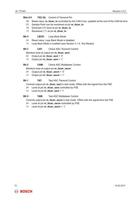
Bits 6:5 TX[1:0]: Control of Transmit Pin<br />
00 Reset value, m_ttcan_tx controlled by the CAN Core, updated at the end of the CAN bit time<br />
01 Sample Point can be monitored at pin m_ttcan_tx<br />
10 Dominant (‘0’) level at pin m_ttcan_tx<br />
11 Recessive (‘1’) at pin m_ttcan_tx<br />
Bit 4 LBCK: Loop Back Mode<br />
0= Reset value, Loop Back Mode is disabled<br />
1= Loop Back Mode is enabled (see Section 3.1.9, Test Modes)<br />
Bit 3 CAT: Check ASC Transmit Control<br />
Monitors level at output pin m_ttcan_asct.<br />
0= Output pin m_ttcan_asct = ‘0’<br />
1= Output pin m_ttcan_asct = ‘1’<br />
Bit 2 CAM: Check ASC Multiplexer Control<br />
Monitors level at output pin m_ttcan_ascm.<br />
0= Output pin m_ttcan_ascm = ‘0’<br />
1= Output pin m_ttcan_ascm = ‘1’<br />
Bit 1TAT: Test ASC Transmit Control<br />
Controls output pin m_ttcan_asct in test mode, ORed with the signal from the FSE<br />
0= Level at pin m_ttcan_asct controlled by FSE<br />
1= Level at pin m_ttcan_asct = ‘1’<br />
Bit 0 TAM: Test ASC Multiplexer Control<br />
Controls output pin m_ttcan_ascm in test mode, ORed with the signal from the FSE<br />
0= Level at pin m_ttcan_ascm controlled by FSE<br />
1= Level at pin m_ttcan_ascm = ‘1’<br />
10 14.02.2013