


You also want an ePaper? Increase the reach of your titles
YUMPU automatically turns print PDFs into web optimized ePapers that Google loves.
ENFORCER Video, Power and Data Balun<br />
Installation:<br />
1. Run UTP cable to the camera where the VPD balun is being installed.<br />
2. Connect the output wires from the power supply to the power input terminal blocks on the balun.<br />
Note: To avoid potential damage, use a voltage meter to ensure proper voltage is present<br />
at the input and output terminal block. Observe correct polarity.<br />
3. Using the included pigtail DC plug, connect the wire end to the VDC output terminal block and<br />
connect the camera to the DC plug. See Fig.1.<br />
4. Connect the video input male BNC connector from the VPD to the camera.<br />
5. If using a RS-485 controlled camera, connect the data input wires to the camera.<br />
6. Using the remaining terminal block, connect the data and video wires to the VPD balun<br />
according to Fig.1.<br />
IMPORTANT – Correct polarity must be observed on all connections.<br />
Troubleshooting:<br />
Wavy or ghost image when<br />
connected to image<br />
processor, but not directly<br />
connected to monitor<br />
Image background flutters<br />
between black and white<br />
Image is wavy and shakes<br />
Image is weak or faded<br />
No image<br />
Poor image quality when<br />
testing using cable on a reel<br />
Move the cable away from possible sources of interference<br />
Install a video amplifier between image processor and balun<br />
Make sure the same twisted pair connects balun at both ends<br />
Replace cable with new cable<br />
Remove power source or adjust monitor’s brightness and<br />
contrast<br />
Reverse polarity of the 2 wires at one of cable<br />
Reduce cable length<br />
Replace with higher grade cable. Cat5 cable meets the<br />
specifications in this manual, Cat6 will extend the range<br />
Check the power supplies of all devices connected to cable<br />
Double-check that the cable is connected properly<br />
Run a continuity test on all wires in the cable<br />
Replace the camera<br />
Test only with cable laid out in such a way that is not coiled<br />
and does not double back on itself<br />
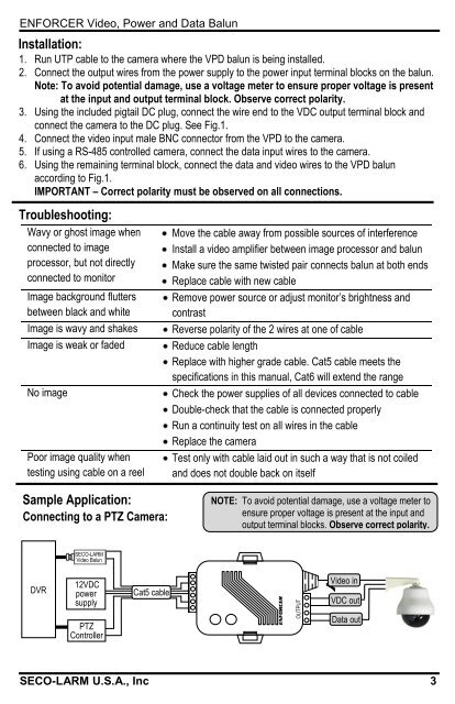
Sample Application:<br />
Connecting to a PTZ Camera:<br />
NOTE: To avoid potential damage, use a voltage meter to<br />
ensure proper voltage is present at the input and<br />
output terminal blocks. Observe correct polarity.<br />
<strong>SECO</strong>-<strong>LARM</strong><br />
Video Balun<br />
DVR<br />
12VDC<br />
power<br />
supply<br />
PTZ<br />
Controller<br />
Cat5 cable<br />
ENFORCER<br />
OUTPUT<br />
Video in<br />
VDC out<br />
Data out<br />
<strong>SECO</strong>-<strong>LARM</strong> U.S.A., Inc 3


