The Oscilloscope and AC Circuits (Lab 09)
The Oscilloscope and AC Circuits (Lab 09)
The Oscilloscope and AC Circuits (Lab 09)
- No tags were found...

Create successful ePaper yourself
Turn your PDF publications into a flip-book with our unique Google optimized e-Paper software.
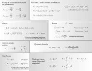
If we applied this sinusoidal voltage source to a resistor, then Ohm’s law would tell us that the<br />
current through the resistor at any instant of time would be given by<br />
V V0<br />
i sin( t)<br />
I<br />
0<br />
sin( t)<br />
.<br />
R R<br />
Note that every time the voltage V reaches a maximum, the current i reaches a maximum. <strong>The</strong><br />
same is true for the voltage <strong>and</strong> current reaching zero or a minimum. We then say that, for a<br />
resistor, the voltage <strong>and</strong> current are "in phase." Note also that Ohm’s law relates the amplitudes<br />
V 0 <strong>and</strong> I 0 .<br />
This behavior is not the same for a capacitor or an inductor when connected to a sinusoidal<br />
voltage source. This is because the voltage <strong>and</strong> current in these devices are related to each other<br />
through a time derivative. For instance, the voltage across an inductor is proportional to the rate<br />
of change of current (di/dt) <strong>and</strong> not simply to i. For inductors <strong>and</strong> capacitors, the voltage <strong>and</strong><br />
current are not in phase. You will learn, in fact, that for a single inductor or a single capacitor<br />
connected to a sinusoidal source, the current <strong>and</strong> voltage are 90° out of phase. In other words,<br />
when V reaches a maximum or minimum, i is zero <strong>and</strong> vice-versa. For a capacitor, the current i is<br />
90° ahead of the voltage, <strong>and</strong> in an inductor, the current is 90° behind the voltage. <strong>The</strong><br />
amplitudes I 0 <strong>and</strong> V 0 are related to each other by something that sort of looks like Ohm's Law:<br />
V<br />
0<br />
I<br />
0<br />
V0<br />
I<br />
0<br />
X<br />
C<br />
<br />
C<br />
I X I ( L)<br />
0<br />
L<br />
0<br />
for a capacitor<br />
for an inductor<br />
(Eq. 1)<br />
Note that the quantity that looks like a "resistance" (technically called a "reactance") changes<br />
with frequency! From Eq. 1, we can see that a capacitor acts like it has a high reactance at low<br />
frequencies <strong>and</strong> a low reactance at high frequencies, while for an inductor it's the other way<br />
around.<br />
Today's lab will focus on a "series RLC" circuit in which we connect a resistor, a capacitor <strong>and</strong><br />
an inductor in series with a sinusoidal voltage. (We will use the oscilloscope to observe what<br />
happens as we vary the frequency of the driving voltage). <strong>The</strong> circuit is as shown below:<br />
R<br />
V = V 0 sin(ωt)<br />
C<br />
Figure 1 A series RLC circuit, in which a sinusoidal voltage source V, drives a current through a resistor R, an<br />
inductor L <strong>and</strong> a capacitor C.<br />
L