The Engineer's Guide to Standards Conversion - Snell
The Engineer's Guide to Standards Conversion - Snell
The Engineer's Guide to Standards Conversion - Snell

You also want an ePaper? Increase the reach of your titles
YUMPU automatically turns print PDFs into web optimized ePapers that Google loves.
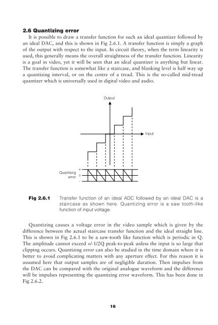
2.6 Quantizing error<br />
It is possible <strong>to</strong> draw a transfer function for such an ideal quantizer followed by<br />
an ideal DAC, and this is shown in Fig 2.6.1. A transfer function is simply a graph<br />
of the output with respect <strong>to</strong> the input. In circuit theory, when the term linearity is<br />
used, this generally means the overall straightness of the transfer function. Linearity<br />
is a goal in video, yet it will be seen that an ideal quantizer is anything but linear.<br />
<strong>The</strong> transfer function is somewhat like a staircase, and blanking level is half way up<br />
a quantizing interval, or on the centre of a tread. This is the so-called mid-tread<br />
quantizer which is universally used in digital video and audio.<br />
Output<br />
Input<br />
Quantisng<br />
error<br />
Fig 2.6.1<br />
Transfer function of an ideal ADC followed by an ideal DAC is a<br />
staircase as shown here. Quantizing error is a saw <strong>to</strong>oth-like<br />
function of input voltage.<br />
Quantizing causes a voltage error in the video sample which is given by the<br />
difference between the actual staircase transfer function and the ideal straight line.<br />
This is shown in Fig 2.6.1 <strong>to</strong> be a saw-<strong>to</strong>oth like function which is periodic in Q.<br />
<strong>The</strong> amplitude cannot exceed +/-1/2Q peak-<strong>to</strong>-peak unless the input is so large that<br />
clipping occurs. Quantizing error can also be studied in the time domain where it is<br />
better <strong>to</strong> avoid complicating matters with any aperture effect. For this reason it is<br />
assumed here that output samples are of negligible duration. <strong>The</strong>n impulses from<br />
the DAC can be compared with the original analogue waveform and the difference<br />
will be impulses representing the quantizing error waveform. This has been done in<br />
Fig 2.6.2.<br />
16