The Engineer's Guide to Standards Conversion - Snell
The Engineer's Guide to Standards Conversion - Snell
The Engineer's Guide to Standards Conversion - Snell

Create successful ePaper yourself
Turn your PDF publications into a flip-book with our unique Google optimized e-Paper software.
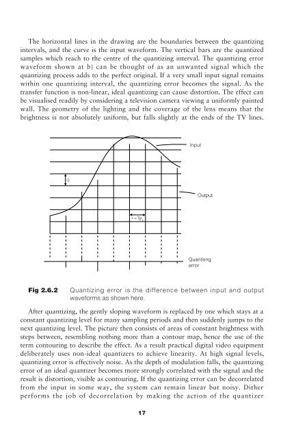
<strong>The</strong> horizontal lines in the drawing are the boundaries between the quantizing<br />
intervals, and the curve is the input waveform. <strong>The</strong> vertical bars are the quantized<br />
samples which reach <strong>to</strong> the centre of the quantizing interval. <strong>The</strong> quantizing error<br />
waveform shown at b) can be thought of as an unwanted signal which the<br />
quantizing process adds <strong>to</strong> the perfect original. If a very small input signal remains<br />
within one quantizing interval, the quantizing error becomes the signal. As the<br />
transfer function is non-linear, ideal quantizing can cause dis<strong>to</strong>rtion. <strong>The</strong> effect can<br />
be visualised readily by considering a television camera viewing a uniformly painted<br />
wall. <strong>The</strong> geometry of the lighting and the coverage of the lens means that the<br />
brightness is not absolutely uniform, but falls slightly at the ends of the TV lines.<br />
Input<br />
Output<br />
Quantisng<br />
error<br />
Fig 2.6.2<br />
Quantizing error is the difference between input and output<br />
waveforms as shown here.<br />
After quantizing, the gently sloping waveform is replaced by one which stays at a<br />
constant quantizing level for many sampling periods and then suddenly jumps <strong>to</strong> the<br />
next quantizing level. <strong>The</strong> picture then consists of areas of constant brightness with<br />
steps between, resembling nothing more than a con<strong>to</strong>ur map, hence the use of the<br />
term con<strong>to</strong>uring <strong>to</strong> describe the effect. As a result practical digital video equipment<br />
deliberately uses non-ideal quantizers <strong>to</strong> achieve linearity. At high signal levels,<br />
quantizing error is effectively noise. As the depth of modulation falls, the quantizing<br />
error of an ideal quantizer becomes more strongly correlated with the signal and the<br />
result is dis<strong>to</strong>rtion, visible as con<strong>to</strong>uring. If the quantizing error can be decorrelated<br />
from the input in some way, the system can remain linear but noisy. Dither<br />
performs the job of decorrelation by making the action of the quantizer<br />
17