2005-10-22 - Division of Solid Mechanics
2005-10-22 - Division of Solid Mechanics
2005-10-22 - Division of Solid Mechanics

You also want an ePaper? Increase the reach of your titles
YUMPU automatically turns print PDFs into web optimized ePapers that Google loves.
SOLUTIONS<br />
to<br />
Examination in Damage <strong>Mechanics</strong> and Life Analysis (TMHL61)<br />
LiTH <strong>2005</strong>-<strong>10</strong>-<strong>22</strong><br />
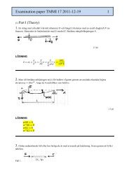
1. (1 point)<br />
(a) What type <strong>of</strong> equation is this<br />
Part 1<br />
ε ij = 1 2 (u i, j + u j,i )<br />
(b) Write the equation in full (without using tensor notations) for i = z and j = x.<br />
Explain the meaning and the contents <strong>of</strong> the expression you give.<br />
(c) What is the relationship between ε zx and ε xz ?<br />
(d) What is the relationship between ε zx and γ zx ?<br />
Solution and answer here:<br />
(a) Equation <strong>of</strong> deformations (compatibility equation)<br />
(b) With i = z and j = x one obtains the shear strain ε zx<br />
ε zx = 1 ⎛ ∂u z<br />
⎜<br />
2 ⎝ ∂x + ∂u x⎞<br />
⎟<br />
∂z ⎠<br />
where u x = u and u z = w are displacements in the x and z direction, respectively. The<br />
displacements are differentiated with respect to x and z, respectively.<br />
(c)<br />
ε zx =ε xz<br />
(d)<br />
ε zx = 1 2 γ zx<br />
2. (1 point)<br />
When using the fracture criterion K I = K Ic three conditions must be fulfilled. Give, and<br />
explain, these three conditions.<br />
Solution and answer here:<br />
Plate thickness (crack tip width) t, crack length a, and remaining length in front <strong>of</strong> the<br />
crack, W−<br />
a, should all be large enough. One has<br />
⎧ t ⎫<br />
⎪ ⎪<br />
⎨ a ⎬<br />
⎪ ⎪<br />
⎩W − a⎭<br />
≥ 2.5 ⎛ ⎜ ⎝<br />
K Ic<br />
σ Y<br />
⎞ ⎟⎠<br />
2<br />
where K Ic is the fracture toughness <strong>of</strong> the material and σ Y is the yield limit <strong>of</strong> the<br />
material.<br />
Plate thickness (crack tip width) t ensures that plane deformation is at hand, crack<br />
length a and remaining length in front <strong>of</strong> the crack W−<br />
a ensure that linear elastic<br />
fracture mechanics (LEFM) can be used.<br />
7 <strong>2005</strong>-<strong>10</strong>-19/TD
Examination in Damage <strong>Mechanics</strong> and Life Analysis (TMHL61)<br />
LiTH <strong>2005</strong>-<strong>10</strong>-<strong>22</strong><br />
Part 1<br />
3. (1 point)<br />
Define the stress intensity range ∆K I (the range <strong>of</strong> the stress intensity factor) that we<br />
use in Paris’ law.<br />
Solution and answer here:<br />
In a case where the loading is varying with time, let K Imax be the maximum value <strong>of</strong> the<br />
stress intensity factor, and K Imin be the minimum value. Then the stress intensity range<br />
∆K I is<br />
∆K I = K Imax − K Imin if K Imin >0<br />
∆K I = K Imax if K Imin
5. (3 points)<br />
( ) 0<br />
Examination in Damage <strong>Mechanics</strong> and Life Analysis (TMHL61)<br />
LiTH <strong>2005</strong>-<strong>10</strong>-<strong>22</strong><br />
y<br />
2 a<br />
2 W<br />
P<br />
x<br />
Part 2<br />
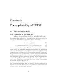
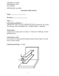
A large thin plate contains a through-thickness crack<br />
with initial crack length 2a 0 = 15 mm. The plate is<br />
loaded by a force P. Upon loading the plate,<br />
symmetric stable crack growth was observed. At load<br />
P = 300 kN the plate fractured. During the loading<br />
the crack opening δ(0) was recorded, and just prior to<br />
the fracture, the crack opening displacement was<br />
found to be δ(0) = 0.12 mm.<br />
Use the Dugdale model to determine the crack length<br />
just before the plate fractured.<br />
P<br />
Numerical data: Modulus <strong>of</strong> elasticity E = 2<strong>10</strong> GPa, yield strength σ Y = 480 MPa, plate<br />
width 2W = 0.4 m and plate thickness t = 0.002 m (i.e. the plate is so thin that the<br />
conditions at the crack tip may be regarded as plane stress).<br />
Solution:<br />
The load P = 300 kN gives stress σ ∞ = P/2Wt = 375 MPa in the plate.<br />
Since plane stress is at hand, the Dugdale model may be used. It gives<br />
δ(0)= 8 σ Y a<br />
E π<br />
Enter the given numerical values and solve for the unknown crack (half-)length a = a crit .<br />
One then obtains<br />
a crit =δ(0) E π ⎛ ⎜⎝ ln 1 + sin(πσ − 1<br />
∞ / 2σ Y ) ⎞<br />
⎟<br />
8 σ Y cos(πσ ∞ / 2σ Y ) ⎠<br />
− 1<br />
2<strong>10</strong> 000 ⋅π⎛<br />
1 + sin(π ⋅ 375 / 2 ⋅ 480) ⎞<br />
= 0.00012 ⎜ln ⎟ = 0.01177 m<br />
8 ⋅ 480 ⎝ cos(π ⋅ 375 / 2 ⋅ 480) ⎠<br />
Thus, the total crack length at failure is 2a crit = 23.54 mm (= 1.57⋅2a 0 ).<br />
ln⎧ ⎨<br />
⎩<br />
1 + sin(πσ ∞ / 2σ Y )<br />
cos(πσ ∞ / 2σ Y )<br />
⎫<br />
⎬<br />
⎭<br />
9 <strong>2005</strong>-<strong>10</strong>-19/TD
6.<br />
Examination in Damage <strong>Mechanics</strong> and Life Analysis (TMHL61)<br />
LiTH <strong>2005</strong>-<strong>10</strong>-<strong>22</strong><br />
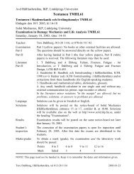
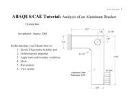
Determine, by use <strong>of</strong> the energy release rate G, the<br />
q 0 stress intensity factor K I for the split beam with a<br />
long crack, see figure. The crack length is a, beam<br />
2h<br />
thickness is b and beam height is 2h, where a >> b<br />
a<br />
and a >> h. The material is linear elastic with<br />
b modulus <strong>of</strong> elasticity E. The beam is loaded<br />
x q 0<br />
symmetrically with two opposite distributed forces<br />
q 0 (N/m). Assume plane stress conditions at the<br />
crack tip.<br />
For a cantilever beam the deflection w(x) due to a<br />
distributed force q 0 is<br />
w(x)= q 0 a 4 ⎧ x 4<br />
⎨<br />
24EI ⎩ a − 4 x 3<br />
4 a + 6 x 2 ⎫<br />
⎬ 3 a 2 ⎭<br />
Solution:<br />
The potential energy Π due to the work performed by the load q 0 is<br />
Π= ⎛ ⎜ ⎝<br />
− P∆<br />
2<br />
⎞<br />
⎟<br />
⎠ = 2 ⎧ ⎨ − 1<br />
⎩ 2<br />
a<br />
⌠ q0 w(x) dx ⎫ ⎬ =−<br />
⌡ ⌠ a q 0 a 4<br />
q0<br />
0 ⎭ ⌡ 0 24EI<br />
=− q 2 0 a 4 ⎧ a 5<br />
⎨<br />
24EI ⎩ 5a − 4 a 4<br />
4 4a + 6 a 3 ⎫<br />
⎬<br />
3 3a =−q 0<br />
2 ⎭<br />
The energy release rate is<br />
(This result can be checked using Problems 5/7(b) and 5/2 in the textbook.)<br />
2 a 4<br />
24EI<br />
⎧<br />
⎨<br />
⎩<br />
6a ⎫<br />
⎬<br />
5<br />
⎧<br />
⎨<br />
⎩<br />
x 4<br />
a 4 − 4 x 3<br />
2 a 5<br />
=−q 0<br />
⎭ 20EI<br />
G =− dΠ<br />
dA =−dΠ bda = 1 q 2 0 5 a 4<br />
b 20EI = q 2 0 5 a 4 12<br />
20b Ebh = 3 q 2 0 a 4<br />
3 Eb 2 h 3<br />
Finally, for plane stress, one has<br />
E 3 q 0<br />
2 a 4<br />
K I = √⎯⎯⎯GE =<br />
√⎯⎯ ⎯<br />
Eb 2 h = √⎯3 q 0 a 2<br />
3<br />
bh√⎯h<br />
a + 6 x 2 ⎫<br />
⎬<br />
3 a dx 2 ⎭<br />
<strong>10</strong> <strong>2005</strong>-<strong>10</strong>-19/TD
Examination in Damage <strong>Mechanics</strong> and Life Analysis (TMHL61)<br />
LiTH <strong>2005</strong>-<strong>10</strong>-<strong>22</strong><br />
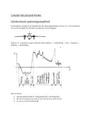
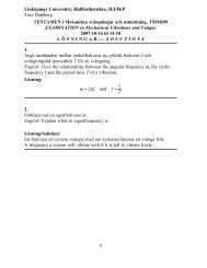
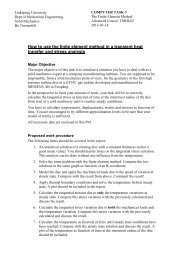
7. (3 points) A loading sequence <strong>of</strong> a structure with an edge crack<br />
0<br />
(see figure) is composed <strong>of</strong> m cycles with pulsating<br />
stress 0 to <strong>10</strong>0 MPa to 0 and one single cycle with<br />
pulsating stress 0 to 175 MPa to 0, see the lower<br />
figure.<br />
Paris’ law for the material reads<br />
a<br />
da<br />
W >> a<br />
dN = 5.1 × <strong>10</strong> − 12 (∆ K I ) 4.17<br />
m per cycle<br />
where ∆K I has the unit MPa m 1/2 (and n = 4.17).<br />
0<br />
(a) Which is the minimum crack length<br />
Stress [MPa]<br />
a min required to give crack propagation at<br />
200<br />
the stress cycle to <strong>10</strong>0 MPa? The<br />
material has threshold value ∆K th =8<br />
MPa m 1/2<br />
<strong>10</strong>0<br />
0<br />
m cycles<br />
one sequence<br />
Solution:<br />
(a) The stress intensity range is<br />
time<br />
(b) Assuming a > a min , how many cycles<br />
m to stress level <strong>10</strong>0 MPa are required to<br />
give the same crack growth as one single<br />
cycle to stress level 175 MPa?<br />
⎛ a ⎞<br />
∆K I =∆σ√⎯⎯πa f 5⎜⎝ ⎟<br />
W ⎠ =∆σ √⎯⎯πa 1.12<br />
Crack propagation will occur when the stress intensity range ∆K I is larger than the<br />
threshold value ∆K th . Stress range <strong>10</strong>0 MPa gives<br />
∆K I = <strong>10</strong>0√⎯⎯πa 1.12 = 8 (=∆K th )<br />
from which a = 0.0016 m is solved. Thus, a should be larger than 1.6 mm.<br />
(b) Paris’ law gives, for a sequence <strong>of</strong> m cycles to stress level <strong>10</strong>0 MPa, the crack<br />
growth per sequence<br />
da<br />
dN s<br />
= 5.1 × <strong>10</strong> − 12 {m ⋅(<strong>10</strong>0 √⎯⎯πa 1.12) 4.17 }<br />
m per sequence<br />
Paris’ law gives, for one cycle to stress 175 MPa, the crack growth per cycle<br />
da<br />
dN = 5.1 × <strong>10</strong> − 12 (175 √⎯⎯πa 1.12) 4.17<br />
m per cycle<br />
The same crack growth in the two cases gives<br />
da<br />
= da<br />
dN s dN giving 5.1 × <strong>10</strong> − 12 m ⋅(<strong>10</strong>0 √⎯⎯πa 1.12) 4.17 = 5.1 × <strong>10</strong> − 12 (175 √⎯⎯πa 1.12) 4.17<br />
from which m = 175 4.17 /<strong>10</strong>0 4.17 = <strong>10</strong>.3 is solved.<br />
Thus, <strong>10</strong>.3 cycles to stress level <strong>10</strong>0 MPa give the same crack growth as one cycle to<br />
stress level 175 MPa.<br />
11 <strong>2005</strong>-<strong>10</strong>-19/TD
8.<br />
Examination in Damage <strong>Mechanics</strong> and Life Analysis (TMHL61)<br />
LiTH <strong>2005</strong>-<strong>10</strong>-<strong>22</strong><br />
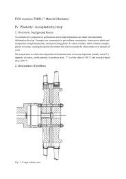
2b<br />
2 a<br />
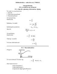
A flat plate has a small elliptical hole, see figure.<br />
The major axis 2b is perpendicular to the direction<br />
<strong>of</strong> the stress. The minor axis is 2a, and b = 1.5a. The<br />
plate is subjected to the stress σ ∞ = <strong>10</strong>0 ± 150 MPa.<br />
Estimate the number <strong>of</strong> stress cycles to fatigue<br />
failure by use <strong>of</strong> Neuber’s method. Assume that K f =<br />
0.9K t .<br />
Use the Ramberg-Osgood’s material relation for amplitudes (E = 200 GPa, K’ = 1344<br />
MPa, n’ = 0.18)<br />
ε a = σ a<br />
E + ⎛ 1 / n’<br />
σ a ⎞<br />
⎜ ⎟ ⎝ K’ ⎠<br />
with appropriate modifications <strong>of</strong> the formula for changes ∆σ <strong>of</strong> the stress.<br />
For the fatigue life analysis, use the C<strong>of</strong>fin-Manson relation, with numerical values σ U<br />
= 800 MPa, and Ψ = 0.65.<br />
Solution:<br />
The stress concentration factor K t is (1 + 2b / a) = 4. No information for calculation <strong>of</strong><br />
the notch sensitivity factor q is given here. Instead, K f = 0.9K t was given. Thus, use K f<br />
= 0.9⋅4 = 3.6.<br />
The maximum local stress σ max and the maximum local strain ε max at the notch are not<br />
needed here, because in C<strong>of</strong>fin-Manson’s relation the stress mean value is not included.<br />
Only the change <strong>of</strong> strain, i.e. the strain range ∆ε, is required. This strain range is<br />
obtained as the point <strong>of</strong> intersection between the Neuber hyperbola and the material<br />
stress-strain relation for load changes. One obtains, for a nominal change <strong>of</strong> stress ∆σ ∞<br />
= 300 MPa (which is the change <strong>of</strong> stress far away from the stress concentration),<br />
⎧<br />
⎪∆σ ⋅ ∆ε = K 2 f (∆σ ∞ ) 2<br />
= 3.62 ⋅ 300 2<br />
E 200 000 = 5.832<br />
⎨<br />
⎪∆ε = ∆σ<br />
⎩ E + 2 ⎛ 1/n’<br />
∆σ ⎞ ∆σ<br />
⎜ ⎟ = ⎝ 2K’ ⎠ 200 000 + 2 ⎛ 1/0.18<br />
∆σ ⎞<br />
⎜ ⎟ ⎝ 2 ⋅ 1344⎠<br />
where ∆σ and ∆ε are changes <strong>of</strong> stress and strain at the stress concentration. From this<br />
system <strong>of</strong> equations ∆ε = 0.007038378 and ∆σ = 828.6 MPa are solved.<br />
Now C<strong>of</strong>fin-Manson’s rule gives<br />
∆ε = 3.5 σ U<br />
E ( N 800<br />
)− 0.12<br />
+ D 0.6 ( N ) − 0.6 = 3.5<br />
200 000 ( N ) − 0.12 + 1.0498 0.6 ( N ) − 0.6<br />
For ∆ε = 0.007038378 one obtains N = 19 375 cycles.<br />
Thus, failure is expected after, approximately, 19 000 cycles.<br />
12 <strong>2005</strong>-<strong>10</strong>-19/TD