2003-01-18 - Division of Solid Mechanics
2003-01-18 - Division of Solid Mechanics
2003-01-18 - Division of Solid Mechanics

Create successful ePaper yourself
Turn your PDF publications into a flip-book with our unique Google optimized e-Paper software.
Avd Hållfasthetslära, IKP, Linköpings Universitet<br />
Tentamen TMHL61<br />
Tentamen i Skademekanik och livslängdsanalys TMHL61<br />
lördagen den <strong>18</strong>/1 <strong>2003</strong>, kl 14-<strong>18</strong><br />
<strong>Solid</strong> <strong>Mechanics</strong>, IKP, Linköping University<br />
Examination in Damage <strong>Mechanics</strong> and Life Analysis TMHL61<br />
Saturday, January <strong>18</strong>, <strong>2003</strong>, time: 14-<strong>18</strong><br />
Teacher: Tore Dahlberg, <strong>01</strong>3-28 1116, or 070-66 511 03.<br />
Examination<br />
Part I<br />
Part II<br />
Part I (yellow papers): No books or other external facilities are allowed.<br />
The questions should be answered directly on the yellow papers.<br />
After having handed in Part I (the four yellow papers), Part II (white<br />
papers) is received. The following literature may then be used:<br />
Literature 1. T Dahlberg and A Ekberg: Failure, Fracture, Fatigue - An<br />
Part II Introduction, or T Dahlberg and A Ekberg: Fatigue and Fracture<br />
Design, LiTH-IKP-S-493<br />
2. Sundström B: Handbok och formelsamling i hållfasthetslära, KTH,<br />
1998 (or G Hedner (ed): KTH Formelsamling i Hållfasthetslära) and/or<br />
extractions from these handbooks (for English-speaking students).<br />
3. Handbooks and mathematical tables, dictionaries, glossary.<br />
4. Any small, handhold calculator in one single unit and without any<br />
external communication (as printer, tape-recorder or others).<br />
In the literature minor notations "in the margin" are allowed, but no<br />
problems, solutions, or answers to problems are allowed.<br />
Language<br />
Solutions<br />
Results<br />
Student’s<br />
inspection<br />
Marks/grades<br />
Solutions can be given in Swedish or English.<br />
Solutions will be posted on the notice-board <strong>of</strong> <strong>Solid</strong> <strong>Mechanics</strong><br />
(Hållfasthetsläras), entrance 15 or 17, corridor B, at <strong>18</strong>.00. Solutions<br />
will be available also on the web at http://www.solid.ikp.liu.se, under<br />
the heading "Examinations".<br />
Examination results will be posted on the same notice-board not later<br />
that January 30, <strong>2003</strong>.<br />
The correction <strong>of</strong> the examination papers is open for inspection until<br />
February 28, <strong>2003</strong>. After this date the exams are distributed to the<br />
students.<br />
To obtain a mark (grade), the examination and the laboratory work<br />
should be passed<br />
Points 0 to 5 6 to 8 9 to 11 12 to 16<br />
Mark failed 3 4 5<br />
NOTE! This page need not be handed in. Keep it to remember the dates and information given.<br />
Tore Dahlberg, Hållfasthetslära, tel <strong>01</strong>3-28 1116 <strong>2003</strong>-<strong>01</strong>-23
Examination in Damage <strong>Mechanics</strong> and Life Analysis (TMHL61)<br />
LiTH <strong>2003</strong>-<strong>01</strong>-<strong>18</strong><br />
Part 1<br />
1. (1 point)<br />
When working with tensor notations, the Kronecker delta, δ ij , is <strong>of</strong>ten very useful.<br />
Explain the use and meaning <strong>of</strong> this symbol.<br />
Solution and answer here:<br />
The symbol δ ij is defined as a tensor with the following property:<br />
δ ij = ⎧ 0 if i ≠ j<br />
⎨<br />
1 if i = j<br />
Indexes i and j stand for the three coordinate directions (x, y, z) or (r, Θ, z) or (1, 2, 3)<br />
and so on.<br />
2. (1 point)<br />
Explain the phenomenon plastic instability.<br />
Solution and answer here:<br />
When a bar is loaded so that yielding occurs, it will be more narrow (cross-sectional<br />
area will decrease), and, due to the plastic deformation, there will be plastic hardening<br />
(deformation hardening) <strong>of</strong> the material. When loading the bar, plastic instability occurs<br />
when the deformation hardening ("increase <strong>of</strong> yield limit") can not compensate for the<br />
area reduction <strong>of</strong> the cross section.<br />
6 <strong>2003</strong>-<strong>01</strong>-23/TD
Examination in Damage <strong>Mechanics</strong> and Life Analysis (TMHL61)<br />
LiTH <strong>2003</strong>-<strong>01</strong>-<strong>18</strong><br />
Part 1<br />
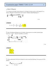
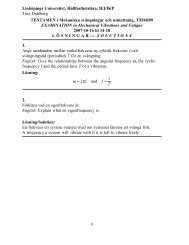
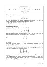
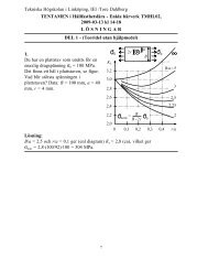
3. (1 point) Constant-amplitude fatigue strengths for materials<br />
subjected to different cyclic loading conditions are<br />
<strong>of</strong>ten expressed in Haigh diagrams. Consider the five<br />
a<br />
loading cases where the loading varies sinusoidally<br />
A<br />
and<br />
1. the mean value σ m is constant,<br />
200<br />
100<br />
B 2. the amplitude σ a is constant,<br />
3. the maximum value σ max (= σ m + σ a ) is constant,<br />
0<br />
0<br />
m<br />
100 200 300 400 MPa<br />
4. the minimum value σ min (= σ m − σ a ) is constant,<br />
and<br />
5. the stress ratio R = σ min /σ max is constant.<br />
In the Haigh diagram given, two straight lines (A<br />
and B) are shown. For each line one <strong>of</strong> the five<br />
loading conditions applies.<br />
(a) Determine which one <strong>of</strong> the five loading variables is constant for line A shown in<br />
the figure (i.e., match line A to one <strong>of</strong> the five loading conditions). Explain your choice.<br />
(b) Determine which one <strong>of</strong> the five loading variables is constant for line B shown in<br />
the figure (i.e., match line B to one <strong>of</strong> the five loading conditions). Explain your choice.<br />
Solution and answer here:<br />
For line A one notices that σ m + σ a is a constant (= 300 MPa). Thus, line A gives that<br />
stress σ max is constant.<br />
For line B one notices that σ m − σ a = σ min is constant (= 200 MPa). Thus, stress σ min is<br />
constant.<br />
Answer:<br />
(a) Line A: stress σ max is constant, (b) line B: stress σ min is constant.<br />
4. (1 point)<br />
To determine the fatigue limit <strong>of</strong> a material, the so-called stair-case method is<br />
sometimes used. Explain the principles, requirements and assumptions <strong>of</strong> this method<br />
(no formulas are needed).<br />
Solution and answer here:<br />
The fatigue testing is performed so that if a test specimen fails (due to fatigue), the next<br />
specimen will be tested at a lower stress level. If it does not fail (becomes a run-out),<br />
the next specimen will be tested at a higher stress lever. Then, assuming that the yield<br />
limit has a normal distribution, and knowing the number <strong>of</strong> failures and run-outs at each<br />
stress level, the mean value and the standard deviation <strong>of</strong> the fatigue limit can be<br />
estimated. This requires that tests performed at a stress level too far away from the<br />
mean value should be rejected.<br />
7 <strong>2003</strong>-<strong>01</strong>-23/TD
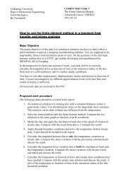
5. (3 points)<br />
( ) 0<br />
Examination in Damage <strong>Mechanics</strong> and Life Analysis (TMHL61)<br />
LiTH <strong>2003</strong>-<strong>01</strong>-<strong>18</strong><br />
y<br />
2 a<br />
2 W<br />
P<br />
x<br />
Part 2<br />
A large thin plate contains a through-thickness crack<br />
with initial crack length 2a 0 = 15 mm. The plate is<br />
loaded by a force P. Upon loading the plate,<br />
symmetric stable crack growth was observed. At load<br />
P = 300 kN the plate fractured. During the loading<br />
the crack opening δ(0) was recorded, and just prior to<br />
the fracture, the crack opening displacement was<br />
found to be δ(0) = 0.1 mm.<br />
Use the Dugdale model to determine the crack length<br />
just before the plate fractured.<br />
P<br />
Numerical data: Modulus <strong>of</strong> elasticity E = 210 GPa, yield strength σ Y = 480 MPa, plate<br />
width 2W = 0.4 m and plate thickness t = 0.002 m (i.e. the plate is so thin that the<br />
conditions at the crack tip may be regarded as plane stress).<br />
Solution:<br />
The load P = 300 kN gives stress σ ∞ = P/2Wt = 375 MPa in the plate.<br />
Since plane stress is at hand, the Dugdale model may be used. It gives<br />
δ(0) = 8 σ Y a 1 + sin(πσ<br />
E π<br />
ln⎧ ∞ /2σ Y ) ⎫<br />
⎨<br />
cos(πσ ∞ /2σ Y )<br />
Enter the given numerical values and solve for the unknown crack (half-)length a = a crit .<br />
One then obtains<br />
a crit<br />
= δ(0) E π ⎛ ⎜⎝ ln 1 + sin(πσ ∞/2σ Y ) ⎞<br />
⎟<br />
8 σ Y cos(πσ ∞ /2σ Y ) ⎠<br />
− 1<br />
210 000 ⋅ π ⎛ 1 + sin(π ⋅ 375/2 ⋅ 480) ⎞<br />
= 0, 00<strong>01</strong> ⎜ln ⎟ = 0, 0098 m<br />
8 ⋅ 480 ⎝ cos(π ⋅ 375/2 ⋅ 480) ⎠<br />
Thus, the total crack length at failure is 2a crit = 19.6 mm (= 1.31⋅2a 0 ).<br />
− 1<br />
⎬<br />
⎭<br />
8 <strong>2003</strong>-<strong>01</strong>-23/TD
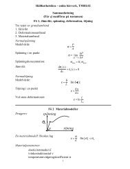
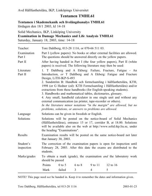
6.<br />
2 h<br />
Examination in Damage <strong>Mechanics</strong> and Life Analysis (TMHL61)<br />
LiTH <strong>2003</strong>-<strong>01</strong>-<strong>18</strong><br />
a<br />
a<br />
a<br />
Q<br />
P<br />
P<br />
Q<br />
M<br />
b<br />
2h<br />
2h<br />
b<br />
Part 2<br />
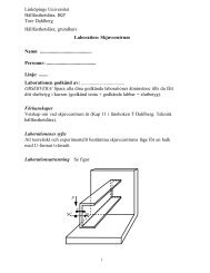
Determine, by use <strong>of</strong> superposition <strong>of</strong> stress intensity<br />
factors, the stress intensity factor K I for the split<br />
beam with a long crack, see figure. The crack length<br />
is a, beam thickness is b and beam height is 2h,<br />
where a >> b and a >> h. The material is linear<br />
elastic with modulus <strong>of</strong> elasticity E. The beam is<br />
loaded symmetrically with two opposite forces P at<br />
the beam ends. The sliding boundary condition to<br />
the right is such that the slope <strong>of</strong> the beam end is<br />
always zero. Assume plane stress conditions.<br />
The following results, taken from Problems 5/2 and<br />
5/3 in the textbook can be used:<br />
Double cantilever beam with stress intensity factor<br />
K I = 2 Qa / bh<br />
Double cantilever beam with energy release rate G =<br />
12M 2 / Eb 2 h 3<br />
Solution:<br />
First, remove the boundary condition to the right and add a bending moment M at the<br />
beam end. The bending moment M should be such that the slope at the free end <strong>of</strong> the<br />
cantilever beam is zero. One obtains, for slope Θ,<br />
a<br />
Q<br />
M<br />
M<br />
√⎺3<br />
which gives M = Qa / 2, and here Q = P<br />
Problem 5/3 gives, for plane stress, that K M I = = 2 M / bh<br />
Now superposition can be used to calculate the stress intensity factor in the case asked<br />
for. One obtains, using M = Qa / 2 and Q = P,<br />
K I = K I Q − K I M = 2 √⎺3 Qa<br />
bh√⎺h<br />
√⎺h<br />
Θ = Q a 2<br />
2EI − M a = 0<br />
EI<br />
√⎺⎺⎺EG √⎺3 √⎺h<br />
− 2 √⎺3 M<br />
bh√⎺h = 2 √⎺3 Qa<br />
bh√⎺h<br />
− 2 √⎺3 Qa<br />
2bh√⎺h = √⎺ 3 Qa<br />
bh√⎺h = √⎺ 3 Pa<br />
bh√⎺h<br />
9 <strong>2003</strong>-<strong>01</strong>-23/TD
Examination in Damage <strong>Mechanics</strong> and Life Analysis (TMHL61)<br />
LiTH <strong>2003</strong>-<strong>01</strong>-<strong>18</strong><br />
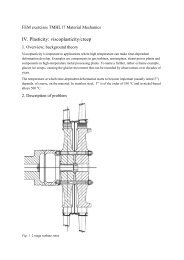
7. (3 points) One type <strong>of</strong> test specimen to determine the<br />
p<br />
fracture toughness <strong>of</strong> a material is the double<br />
cantilever beam, see figure. The height is 2h<br />
= 30 mm (the width t is large).<br />
At plane strain, the stress intensity factor can<br />
2 h be written<br />
p<br />
a<br />
where ν is the Poisson ratio, ν = 0.3, and p is<br />
the loading per unit <strong>of</strong> the width <strong>of</strong> the test<br />
specimen.<br />
Paris’ law for the material reads da<br />
dN = 5.1 × 10 − 12 (∆ K I ) 3<br />
m per cycle<br />
where ∆K I has the unit MPa m 1/2 .<br />
The fracture toughness <strong>of</strong> the material is (in this example) determined in the following<br />
way: First a crack <strong>of</strong> length a 0 = 20 mm is created by machining. Then, to obtain a<br />
sharp crack tip, the test specimen is subjected to a loading p such that the load p is<br />
cycled between 0 och 0.9 MN/m. This is done for N = 15 000 cycles. When this is done<br />
the cyclic loading is stopped.<br />
(a) Calculate the crack length a final obtained by the cyclic loading.<br />
After this, the test specimen is loaded by a static, monotonically increasing load p until<br />
fracture occurs. One obtains the final fracture <strong>of</strong> the specimen at load p = 1.8 MN/m.<br />
(b) Determine the fracture toughness <strong>of</strong> the material.<br />
The yield limit <strong>of</strong> the material is σ s = σ Y = 1000 MPa.<br />
Solution: (a) First determine the crack length after the cyclic loading. Paris’ law gives<br />
Which gives<br />
da<br />
dN = 5.1 × 10 ⎛ 3<br />
− 12 2√⎺3 0.9 a ⎞<br />
⎜ ⎟⎠ ⎝ 0.91 0.<strong>01</strong>5 3 / 2<br />
1 ⎧<br />
− 2<br />
from which is solved a final = 25.754 mm.<br />
(b) At the final, monotonically increasing loading the critical crack length is a final =<br />
25.754 mm. The fracture toughness is obtained from<br />
K I = K Ic = 2 √⎺3 p failure a final<br />
= 96.06 MPa√⎺m<br />
1 − ν 2 h 3/2<br />
Thus K Ic = 96 MPa m 1/2 .<br />
Here linear elastic fracture mechanics (LEFM) was used. Was it allowed?<br />
One has<br />
2.5 ⎛ 2<br />
K Ic ⎞<br />
⎜ ⎟⎠ = 2.5 ⎛ 2<br />
96 ⎞<br />
⎜ ⎟ = 0.023 m < a ⎝ σ Y ⎝ 1000⎠<br />
final = 0.02575 m<br />
Thus, it was OK to use LEFM for the final failure.<br />
⎨<br />
<br />
a final<br />
m per cycle<br />
K I = 2 √⎺3<br />
1 − ν 2 p a<br />
h 3/2<br />
1<br />
− 1 ⎫<br />
⎬<br />
2 2<br />
a = 0.033078 ⋅ N = 496.16 0 ⎭ (1/m2 )<br />
10 <strong>2003</strong>-<strong>01</strong>-23/TD
Examination in Damage <strong>Mechanics</strong> and Life Analysis (TMHL61)<br />
LiTH 2002-10-2<br />
Part 2<br />
8. (3 points)<br />
To determine the fatigue limit <strong>of</strong> a material a number <strong>of</strong> experiments were performed<br />
according to the "staircase" method. Calculate an estimation <strong>of</strong> the mean value and the<br />
standard deviation <strong>of</strong> the fatigue limit <strong>of</strong> the material if the following test series were<br />
obtained (stresses in MPa)<br />
σ a = 90, 99, 108, 117, 126, 117, 108, 117, 126, 117, 126, 135, 126, 117, 108, 117, 126,<br />
117, 126, 117, 108, 117 MPa,<br />
where the last test (117 MPa) became a run-out. The fatigue limit is supposed to have a<br />
normal distribution.<br />
Solution:<br />
From the load levels used in the test it is concluded that the test specimens failed<br />
(indicated by an F) or did not fail (became run-outs, indicated by RO) as follows:<br />
σ a = 90(RO), 99(RO), 108(RO), 117(RO), 126(F), 117(F), 108(RO), 117(RO), 126(F),<br />
117(RO), 126(RO), 135(F), 126(F), 117(F), 108(RO), 117(RO), 126(F), 117(RO),<br />
126(F), 117(F), 108(RO), 117(RO) MPa.<br />
The test series seems to have started on a too low stress level. Therefore, from the 22<br />
tests the first three tests are discarded (the first change from run-out to failure came at<br />
stress level 117 MPa). From the remaining 19 tests 10 are run-outs and 9 are failures.<br />
The less frequent event should be analysed. Thus, analyse the failures. The failures<br />
occurred at<br />
σ a = 126(F), 117(F), 126(F), 135(F), 126(F), 117(F), 126(F), 126(F), 117(F) MPa.<br />
These events give the following table (see compendium)<br />
I II III IV V<br />
117 0 3 0 0<br />
126 1 5 5 5<br />
135 2 1 2 4<br />
N = 9 A = 7 B = 9<br />
The mean value <strong>of</strong> the fatigue limit is estimated to (step d = 9 MPa)<br />
S’ m = S 0 + d ⎧ A<br />
⎨<br />
N − 1 ⎫<br />
⎬<br />
2<br />
= 117 + 9 ⎧ 7<br />
⎨<br />
⎭ 9 − 1 ⎫<br />
⎬ = 120 MPa<br />
2⎭ Further, one obtains<br />
NB − A 2<br />
= 9 ⋅ 9 − 72<br />
= 0.395<br />
N 2 9 2<br />
The standard deviation <strong>of</strong> the fatigue limit is estimated to<br />
s’ = 1.62d ⎧ NB − A 2<br />
⎨ + 0.029 ⎫ ⎬ = 6.2 MPa<br />
⎭<br />
N 2<br />
11 <strong>2003</strong>-<strong>01</strong>-23/TD