Parametric Design Process of a Complex Building In Practice Using ...
Parametric Design Process of a Complex Building In Practice Using ...
Parametric Design Process of a Complex Building In Practice Using ...

You also want an ePaper? Increase the reach of your titles
YUMPU automatically turns print PDFs into web optimized ePapers that Google loves.
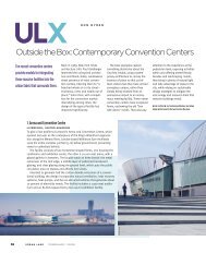
<strong>Parametric</strong> <strong>Design</strong><br />
<strong>Process</strong> <strong>of</strong> a <strong>Complex</strong><br />
<strong>Building</strong> <strong>In</strong> <strong>Practice</strong><br />
<strong>Using</strong> Programmed Code<br />
As Master Model<br />
Kat Park and Nicholas Holt<br />
international journal <strong>of</strong> architectural computing<br />
issue 03, volume 08<br />
359
<strong>Parametric</strong> <strong>Design</strong> <strong>Process</strong> <strong>of</strong> a <strong>Complex</strong> <strong>Building</strong><br />
<strong>In</strong> <strong>Practice</strong> <strong>Using</strong> Programmed Code As Master<br />
Model<br />
Kat Park and Nicholas Holt<br />
Abstract<br />
Parameter based design explorations inevitably require a unified master<br />
model that represents the current design state, where each parameter<br />
being explored is essentially a critical sub-case <strong>of</strong> this master model.<br />
Throughout the constantly changing design state, it is beneficial to<br />
maintain a master model that is flexible and adaptive.This paper<br />
describes the design process <strong>of</strong> a complex building whose master<br />
model documented the design logic through implementation <strong>of</strong><br />
s<strong>of</strong>tware code.This process is illustrated by the case study <strong>of</strong> Lotte<br />
Super Tower (Seoul, Korea) from the beginning <strong>of</strong> schematic design to<br />
end <strong>of</strong> construction document phase. By maintaining the master model<br />
as a platform-free s<strong>of</strong>tware code, in contrast to platform-dependent<br />
methods, the case study illuminates the advantages <strong>of</strong> documenting the<br />
generative logic behind design variations in a way that allows greater<br />
flexibility and a higher level <strong>of</strong> alignment with design intent.<br />
360
1. <strong>In</strong>troduction<br />
<strong>In</strong>tegrating parametric models into the process <strong>of</strong> design requires a<br />
formalization <strong>of</strong> the generative logic and a systematic way <strong>of</strong> evolving this logic<br />
in concert with design changes.A successful master model must, therefore,<br />
keep track <strong>of</strong> the various parameters being explored.The critical sub-cases<br />
that these parameters represent might be as simple as studying the effects <strong>of</strong> a<br />
numerical value on the building’s form or a much more complex set <strong>of</strong> values<br />
that explore the building’s response to factors such as environmental<br />
conditions. <strong>In</strong> the more complex scenarios it might be more efficient for the<br />
explorations to take place outside <strong>of</strong> the master model; nevertheless, whatever<br />
design decisions might have been made need to be fed back into the master<br />
model in order to propagate its influence on the overall design, as well as<br />
manage the relationships among the various sub-cases. <strong>Parametric</strong><br />
representation <strong>of</strong> a design is a constantly evolving task, since most complex<br />
design problems in practice are continually reacting to addition and deletion<br />
<strong>of</strong> inputs at multiple scales and levels <strong>of</strong> complexity. Setting up a parametric<br />
model requires defining the major parameters in the initial stage, but this<br />
initial set <strong>of</strong> parameters continues to grow and change as the project<br />
develops into different stages. <strong>Parametric</strong> modeling platforms existing today<br />
<strong>of</strong>fer assistance in defining the parameters and their associative<br />
relationships; however, it is inevitable that using their predefined set <strong>of</strong> tools<br />
will make the representation dependent on the specific platform.The notion<br />
that availability <strong>of</strong> a tool invites use is well accepted in design.[1] Different<br />
modeling platforms demand the end-user to have differing levels <strong>of</strong><br />
understanding and rigor in the process <strong>of</strong> defining the parameters and their<br />
relationships. Rigor obtained through the constraints opposed by a s<strong>of</strong>tware<br />
platform is not only limited and <strong>of</strong>ten biased, but it is also dependent on the<br />
form defined by the platform.As design process is inherently “parametric,” it<br />
is important that designers use an open platform that is most appropriate<br />
for building the relationships as they arise.<br />
The main roles that should be fulfilled by the unified master model are:<br />
• <strong>of</strong>fer a platform for the iterative-evaluative loop for design options<br />
• capture and document knowledge <strong>of</strong> other related disciplines<br />
affecting the design<br />
• provide a platform for negotiating optimization <strong>of</strong> competing<br />
disciplines.<br />
This paper demonstrates a new method <strong>of</strong> managing a complex<br />
parametric design system where programmed code captures the<br />
understanding <strong>of</strong> the inherent generative logic as well as how the system<br />
might be constructed or fabricated in an efficient and flexible way, while<br />
fulfilling the main roles <strong>of</strong> a master model mentioned above.<br />
<strong>Parametric</strong> <strong>Design</strong> <strong>Process</strong> <strong>of</strong> a <strong>Complex</strong> <strong>Building</strong> <strong>In</strong> <strong>Practice</strong><br />
<strong>Using</strong> Programmed Code As Master Model<br />
361
2. Existing Approaches to Master Data Models<br />
It is commonly agreed that all design tools have particular affordances and<br />
biases, and they implicitly embody particular assumptions and values. <strong>In</strong><br />
general, a designer’s toolkit represents a provisional equilibrium <strong>of</strong> capability<br />
and demand.[1] <strong>In</strong> this section, we provide an overview <strong>of</strong> design tools<br />
commonly used in practice to aid in the design <strong>of</strong> projects similar in scale<br />
and complexity to Lotte Super Tower, seek to illuminate the assumptions<br />
and values embodied in each, and assess how well each meets the criteria <strong>of</strong><br />
a successful unified master model as outlined above.<br />
2.1. Master Data Model <strong>Using</strong> Non-parametric Platforms<br />
Non-parametric methods <strong>of</strong> representing a design are the most widely used<br />
digital design tool in today’s practice, and thus provide a baseline against<br />
which to asses the value <strong>of</strong> more advanced techniques. Setting up the logic<br />
for a parametric model requires initial investment <strong>of</strong> time and effort, which<br />
always need to be evaluated against the projected lifespan <strong>of</strong> the model.A<br />
quick conceptual study might sometimes call for a model without the need<br />
to document the logic or associative relationships, or the initial resources<br />
might simply not be available.<br />
A 3D Rhinoceros model <strong>of</strong> a form (without the use <strong>of</strong> Grasshopper<br />
plug-in) is an example <strong>of</strong> non-parametric modeling platform. <strong>In</strong> this platform,<br />
one method <strong>of</strong> exploring or documenting design intent is to use<br />
geometrical elements and geometrical operation tools <strong>of</strong>fered by Rhino.This<br />
method is perhaps most susceptible to the design being influenced by the<br />
tool.While a complete account <strong>of</strong> modeling by direct manipulation <strong>of</strong> the<br />
geometry suggests a design process that is beyond the scope <strong>of</strong> this paper,<br />
we may speculate that a systematic approach to form-generation is possible<br />
in this media by using points, construction lines, etc, to leave a trace <strong>of</strong> the<br />
logic applied in creating the form. <strong>In</strong> other words, the subassembly <strong>of</strong> parts<br />
used to create the desired form is deliberately saved by the operator.<br />
Figure 1. Construction figures are<br />
saved in order to document the design<br />
generation explicitly<br />
362 Kat Park and Nicholas Holt
This approach, the manual parametric exploration, leaves a history <strong>of</strong> the<br />
generative logic, but the set <strong>of</strong> data representing this logic is rarely<br />
recoverable and difficult to decipher. More <strong>of</strong>ten than not, different design<br />
options created in this manner require similar amount <strong>of</strong> data and workhours<br />
for each additional option. If this method persists into the later stages<br />
<strong>of</strong> design, the representation needs to be updated to the new design state<br />
by repeating the modeling effort each time.While this representation might<br />
capture the knowledge <strong>of</strong> a partnering discipline (for instance, duct size<br />
coordination with mechanical consultants requires the floor-to-floor height<br />
<strong>of</strong> the model to change), the knowledge is indirectly embedded in the<br />
model, and thus hidden.<br />
2.2. Master Data Model <strong>Using</strong> BIM Platforms<br />
<strong>Parametric</strong> modeling have matured in recent years well beyond the state <strong>of</strong><br />
art when they first appeared on the pr<strong>of</strong>essional architectural design stage,<br />
both in terms <strong>of</strong> computational power and well-resolved user interface. BIM<br />
systems like Autodesk Revit and Dessau’s Digital Project provide a platform<br />
to represent and manage 3D building components and systems, capable <strong>of</strong><br />
integrating the various members in design and construction phase such as<br />
structural engineers, MEP engineers, and fabricators. By applying objectbased<br />
parametric modeling, controlled manipulation <strong>of</strong> properties and<br />
inheritance, these platforms organize the building data using the general<br />
object-oriented computation concepts.These platforms run behind an<br />
interface that is slightly closer to how the s<strong>of</strong>tware themselves operate than<br />
their predecessors, and require that the user learn the structure <strong>of</strong> their<br />
language. <strong>In</strong> exchange for this greater investment on the part <strong>of</strong> the user,<br />
the database becomes more computer-interpretable, which carries with it a<br />
wide range <strong>of</strong> advantages: exporting quantities <strong>of</strong> materials and assorted<br />
other metadata about the components and systems, carrying two-way links<br />
to building specifications, automatically translating the design information<br />
into analysis applications, integrating energy, structural and user simulations<br />
to inform the design, and many more.[2]<br />
One <strong>of</strong> the key benefits <strong>of</strong> such BIM system is to create a single central<br />
model that can be explored from the view <strong>of</strong> multiple disciplines <strong>of</strong> the<br />
design. <strong>In</strong>tegrated coordination with structure or MEP arm <strong>of</strong> design is<br />
possible when the “architectural model” is compared to “structural model”<br />
through clash-detection; but much <strong>of</strong> this expectation-realignment can<br />
happen at a conceptual level if there were an efficient way to communicate<br />
the design logic or the structural logic.With Revit or DP master models,<br />
the architectural model can be coordinated with the structural model only<br />
when the structural engineers have put together a structural model. <strong>In</strong> initial<br />
form-finding stages, the current set <strong>of</strong> interfaces in Revit imposes more<br />
constraints than invite use. More <strong>of</strong>ten than not, formal explorations are<br />
executed elsewhere (typically a more flexible environment such as Rhino)<br />
<strong>Parametric</strong> <strong>Design</strong> <strong>Process</strong> <strong>of</strong> a <strong>Complex</strong> <strong>Building</strong> <strong>In</strong> <strong>Practice</strong><br />
<strong>Using</strong> Programmed Code As Master Model<br />
363
and imported into Revit in order to document or append more<br />
construction-relevant data. For this reason, it is difficult to discuss Revit’s<br />
current state as a parametric design platform, as it is used more successfully<br />
as a project delivery platform.<br />
Figure 2. Digital Project’s<br />
Specification Tree organizes the<br />
parameter set and relationships into a<br />
tree structure<br />
Digital Project’s engineering-caliber geometry engine provides the<br />
designer a toolkit for constructing complex 3D surfaces and solids.They<br />
provide abstractions and interfaces to help define the design problem,<br />
interfaces to organize and manage the parameters and their relationships<br />
with each other.The specification tree lists all the geometry and features<br />
but this organization method is rigid which binds the designer to think <strong>of</strong><br />
the parameters in a particular, Digital Project-centric way. Moreover, unless<br />
the associations and parametric relationships have been developed properly<br />
to anticipate certain changes, not only is it difficult to alter them, it is<br />
difficult to maintain any parts that depend on a relationship that might need<br />
to change. Especially at earlier stages <strong>of</strong> design, such constraints imposed by<br />
the platform are not desirable. Scripting or creating macros within DP can<br />
relieve some <strong>of</strong> the rigidity but the user is still tied to the platform-specific<br />
geometrical primitives. For example, a designer might speed up the<br />
generation <strong>of</strong> surfaces through a script, but the script must refer to the DP<br />
definition <strong>of</strong> a surface, not a mathematical definition <strong>of</strong> a surface.The<br />
parametric modeling toolset inherent in these BIM systems provide a<br />
snapshot <strong>of</strong> the artifact being designed; but they cannot capture the intent<br />
or the progression <strong>of</strong> the design logic through various iterations and<br />
changes, either due to immaturity <strong>of</strong> the toolset or its rigidity.<br />
2.3. Master Data Model <strong>Using</strong> <strong>Parametric</strong> <strong>Design</strong> Platforms<br />
McNeel’s Grasshopper is much more flexible as a parametric design tool.<br />
The designer can explore multiple ways <strong>of</strong> generating one form or element,<br />
364 Kat Park and Nicholas Holt
which can be easily saved as a cluster <strong>of</strong> modules, <strong>of</strong>ten within the same<br />
Grasshopper file.This allows the designer to save the generative logic in an<br />
efficient, organized manner. Nevertheless, the designer is still tied to a very<br />
particular user interface, and consequently, only explore within its<br />
boundaries under its indirect design influences. For instance, one quickly<br />
runs into the way data structures are inherently handled within all the<br />
modules and its large influence in many <strong>of</strong> the tasks. Because the data<br />
structures are required to be set up in a particular way, users <strong>of</strong>ten resort<br />
to creating workaround solutions rather than build a parametric<br />
relationship or association that is intuitive to them. Creating one’s own<br />
modules have recently become fairly easy, which have added greater<br />
flexibility. More importantly, Grasshopper has not yet been able to handle<br />
the amount <strong>of</strong> data or complexity <strong>of</strong> a project described in this paper.<br />
3. Case Study <strong>of</strong> Lotte Super Tower<br />
3.1. Project Background<br />
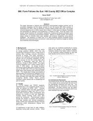
The geometry <strong>of</strong> 555m tall Lotte Super Tower begins with a constant<br />
transformation from a square base to a circle top.This idea is conceptually<br />
structural as well as architectural: transformation in order to shed wind<br />
vortices which occur in unchanging form, taper for efficient mass<br />
distribution <strong>of</strong> mixed-use program which require varying lease spans.The<br />
geometrical challenge <strong>of</strong> transforming a square into a circle was resolved by<br />
creating triangular facets on the building.<br />
Figure 3. Lotte Super Tower<br />
<strong>Parametric</strong> <strong>Design</strong> <strong>Process</strong> <strong>of</strong> a <strong>Complex</strong> <strong>Building</strong> <strong>In</strong> <strong>Practice</strong><br />
<strong>Using</strong> Programmed Code As Master Model<br />
365
3.2. <strong>Design</strong> Variation Exploration<br />
It is important to note that the master model described here did not grow<br />
out <strong>of</strong> a desire to extend the capabilities <strong>of</strong> AUTOCAD platform as a design<br />
tool, but rather the need for a platform for the mathematical development <strong>of</strong><br />
the geometrical design moves evolving in the tower.The operations in the<br />
programmed code did not use AUTOCAD specific functions, but AUTOLISP<br />
was used for its ease <strong>of</strong> handling lists <strong>of</strong> data.The formulas and generative<br />
logic were described in the code with AUTOLISP; the parameter values were<br />
kept in a separate configuration file that the s<strong>of</strong>tware read in as part <strong>of</strong> its<br />
initialization process; and different forms <strong>of</strong> outputs were generated for<br />
different needs.The series <strong>of</strong> configuration files, each associated with a<br />
specific version <strong>of</strong> the logic file, made it possible to keep an organized record<br />
<strong>of</strong> design status as constant changes were being applied.<br />
Figure 4 shows a simple example <strong>of</strong> the descriptive logic that was used<br />
to provide iterative-evaluative loop for design exploration in the initial<br />
phase <strong>of</strong> the project: the overall dimension or the number <strong>of</strong> facet modules<br />
for proportional evaluation, as well as functional evaluation such as floor<br />
plate dimension requirements, enclosed area, etc.<br />
Figure 4. <strong>In</strong>itial parameter<br />
set for overall tower<br />
dimensions, subdivision<br />
modules, and their<br />
relationships.<br />
Figure 5 shows the simple parameter set and their relationships from<br />
Figure 4 translated into a function named BuildData in AUTOLISP code.As<br />
mentioned previously, the specific values <strong>of</strong> the parameters are stored in a<br />
separate configurations file in order to keep an organized history <strong>of</strong> the<br />
values at different design stages, <strong>of</strong>ten accompanied by the reasons for their<br />
change from the previous version.The BuildData function abstracts the idea<br />
<strong>of</strong> a line at the top and bottom <strong>of</strong> the tower, not a circle or a rectangle.This<br />
lower-level <strong>of</strong> abstraction allowed the flexibility <strong>of</strong> changing the top figure<br />
366 Kat Park and Nicholas Holt
Figure 5. Function BuildData builds<br />
the list <strong>of</strong> intermediate points for<br />
subdivision modules at various<br />
elevation<br />
into a square (which was one <strong>of</strong> the numerous design explorations the<br />
project went through) or a circle.This kind <strong>of</strong> flexibility can <strong>of</strong>ten be difficult<br />
to achieve when the platform restricts the operator to use its specific set <strong>of</strong><br />
user interface tools to create parametric relationships.<br />
3.3. Knowledge Capture <strong>of</strong> Partnering Disciplines<br />
Documenting the generative logic into s<strong>of</strong>tware code also allowed<br />
coordination <strong>of</strong> design intent with structural engineers to begin at a<br />
conceptual level, as well as capture their knowledge into the master model.<br />
The optimal angle for the diagrid structure (diagonal columns than span<br />
the subdivided arcs across the discretized elevation points) was determined<br />
mathematically as a function <strong>of</strong> the load each member was required to<br />
carry at their individual locations. Since the angles cannot change midmember,<br />
the results from the theoretical solution was reinterpreted with<br />
discrete values pertaining to the dimension <strong>of</strong> the diagrid, which is shown in<br />
dark blue lines in Figure 6.Translating this type <strong>of</strong> information into s<strong>of</strong>tware<br />
code allowed the communication between the design team and the<br />
structural engineers to remain at a level that provided accuracy and<br />
efficiency unachievable by 3D models.The values <strong>of</strong> zn elevations specified<br />
at right in Figure 6 indicates where these structural diagrid discretizations<br />
occur in the tower.These values were primarily determined by<br />
programmatic and architectural requirements, which also fluctuated<br />
throughout the design phases.The exact nature <strong>of</strong> the lines which connect<br />
the top arc and bottom line, as well as the logic <strong>of</strong> exactly how these<br />
<strong>Parametric</strong> <strong>Design</strong> <strong>Process</strong> <strong>of</strong> a <strong>Complex</strong> <strong>Building</strong> <strong>In</strong> <strong>Practice</strong><br />
<strong>Using</strong> Programmed Code As Master Model<br />
367
discretizations occur along the lines were all design explorations that<br />
affected architecture as well as structure.These ideas were translated into<br />
code and passed back and forth with the structural engineers sometimes as<br />
code, sometimes as pseudo-code.When parameter values changed,<br />
coordination was as easy as communicating a new set <strong>of</strong> values, since both<br />
disciplines had already agreed on the parameter logic and their relationships<br />
through code.This type <strong>of</strong> platform-independent communication between<br />
the disciplines facilitated a generative - as opposed to a strictly analytical -<br />
structural design consultancy, and provided significant flexibility in contrast<br />
to the platforms typically used by architects and structural engineers.<br />
Figure 6. Left: Engaging Structural<br />
Engineer’s theoretical solution to the<br />
optimal diagrid angles. Right:The final<br />
values <strong>of</strong> z n<br />
elevations documented at<br />
the end <strong>of</strong> Construction Documents<br />
phase.<br />
3.4. Documentation <strong>of</strong> Critical Sub-Cases<br />
The master model served as a central repository <strong>of</strong> various iterations and<br />
results obtained from specific analysis.This section describes two such<br />
cases: installation feasibility and fabrication analysis <strong>of</strong> exterior wall detail<br />
and exterior wall panelization strategies.<br />
368 Kat Park and Nicholas Holt
Exterior Wall Fabrication Analysis<br />
Rule-based logic documentation was critical in exploring the building’s<br />
exterior wall design, since the geometry <strong>of</strong> the tower’s exterior wall was<br />
determined by <strong>of</strong>fsetting the structure’s centroidal wireframe in a systematic<br />
manner.After exploring numerous <strong>of</strong>fset methods, we found that the size <strong>of</strong><br />
the diagrid nodes was the governing factor in determining the specific <strong>of</strong>fset<br />
dimensions. <strong>In</strong> other words, the final <strong>of</strong>fset dimension values specified in<br />
Figure 7 represents the minimum distance necessary for the exterior wall<br />
to clear the structural diagrid nodes at each elevation.The new set <strong>of</strong><br />
horizontals derived from this method defined the external boundary <strong>of</strong> the<br />
exterior wall.<br />
Figure 7.An example <strong>of</strong> structure<br />
to exterior wall relationship<br />
description<br />
After the horizontal <strong>of</strong>fsets were determined, the diagonal centroid<br />
which locates the line <strong>of</strong> the diagrid structure was <strong>of</strong>fset as well. Defining<br />
this relationship between structure and curtain wall was a complex task,<br />
since it spanned from a problem <strong>of</strong> geometrical concept all the way to<br />
understanding fabrication and installation requirements.<br />
The following diagrams show one example <strong>of</strong> the <strong>of</strong>fset strategy which<br />
was explored in order to determine a structure-to-exterior-wall<br />
relationship that satisfied multiple conditions.<br />
<strong>Parametric</strong> <strong>Design</strong> <strong>Process</strong> <strong>of</strong> a <strong>Complex</strong> <strong>Building</strong> <strong>In</strong> <strong>Practice</strong><br />
<strong>Using</strong> Programmed Code As Master Model<br />
369
Figure 8.An example <strong>of</strong><br />
generative logic for defining the<br />
relationship between structural<br />
centroid and exterior wall<br />
Figure 9.An example <strong>of</strong><br />
generative logic (the exploded<br />
option) for exterior wall<br />
expression panel geometry.<br />
Expression panel zone is defined<br />
by the dotted lines enclosing the<br />
gap between surfaces<br />
The variations <strong>of</strong> <strong>of</strong>fset strategies were designed with rule-based logic in<br />
the master model, after which the results were exported to be visualized in<br />
renderings and drawings to ensure design intent.At the same time, the<br />
relationship was tested for fabrication feasibility through a more<br />
comprehensive torque analysis in Digital Project.This required the master<br />
model to output the exterior wall geometry and the structural geometry<br />
into a set <strong>of</strong> coordinate data that could be read into Digital Project.<br />
370 Kat Park and Nicholas Holt
Figure 10. <strong>Design</strong> model output as<br />
coordinate data for importing into<br />
other analysis platforms.<br />
More than ten different geometrical relationships between structure and<br />
exterior wall were explored during this process, and since all the<br />
relationships were documented as s<strong>of</strong>tware code, generating the result <strong>of</strong> a<br />
particular <strong>of</strong>fset method as coordinate data (delimited text file) was natural.<br />
Maintaining the logic as programmed code allowed flexibility to produce<br />
various outputs each catered for different needs, eliminating the problem <strong>of</strong><br />
competing file formats prevalent in traditional BIM approach. Figure 10<br />
depicts one particular example <strong>of</strong> the coordinate data generated for the<br />
triangular facets which describe the surface <strong>of</strong> the exterior wall.This<br />
coordinate data was imported into a Digital Project model to measure the<br />
level <strong>of</strong> torque or clearance in order to ensure ease <strong>of</strong> fabrication and<br />
installation. Modeling the multiple variations <strong>of</strong> the relationship between the<br />
structure and exterior wall with a parametric platform like Digital Project<br />
would not only have taken much longer due to its heaviness, but also would<br />
have required a specification tree size similar to that <strong>of</strong> multiple (and<br />
separate) instances <strong>of</strong> the model.This is a clear advantage <strong>of</strong> maintaining a<br />
master model as a central repository <strong>of</strong> design logic, both documenting<br />
design intention and capturing the recommendations <strong>of</strong> fabrication and<br />
construction consultants.<br />
Exterior Wall Panelization<br />
The exterior wall <strong>of</strong> the tower is divided into three distinct sections, each<br />
<strong>Parametric</strong> <strong>Design</strong> <strong>Process</strong> <strong>of</strong> a <strong>Complex</strong> <strong>Building</strong> <strong>In</strong> <strong>Practice</strong><br />
<strong>Using</strong> Programmed Code As Master Model<br />
371
with different set <strong>of</strong> conditions and characteristics that required a different<br />
panelization logic:<br />
1. At podium, the exterior wall is composed <strong>of</strong> approximately 45m<br />
tall cable net wall.Therefore, panelization strategy prioritizes<br />
continuation <strong>of</strong> structure cables across adjacent triangular facets<br />
(tri-surfaces).<br />
2. Most <strong>of</strong> the <strong>of</strong>fice and hotel zone <strong>of</strong> the tower is curtain wall.<br />
Anticipating interior partitions, perpendicular mullion fabrication<br />
takes priority over mullion alignment across adjacent tri-surfaces. <strong>In</strong><br />
a few cases, the anchor point <strong>of</strong> the vertical grid shifts to straddle<br />
the midpoint <strong>of</strong> the triangle, rather than coincide with the<br />
midpoint.This was a simple solution to maximize mullion alignment<br />
across adjacent tri-surfaces.<br />
3. The exterior wall at the observation deck and restaurant zone is<br />
free from any interior wall module requirement; therefore, visual<br />
transparency is prioritized.To minimize view obstruction, cable net<br />
structure is defined by a diagonal grid, producing diamond or<br />
triangle panels.<br />
Due to the taper and transformation in the tower form, each triangular<br />
facet (tri-surface) <strong>of</strong> the exterior surface resulted in a unique geometry,<br />
aside from the reflective symmetry across the center <strong>of</strong> the overall surface.<br />
Therefore, it was necessary to handle panelization <strong>of</strong> each surface<br />
individually.The logic <strong>of</strong> how each surface should be panelized was explored<br />
and documented in the s<strong>of</strong>tware code; and depending on the location <strong>of</strong> the<br />
surface, one <strong>of</strong> final three strategies mentioned above were applied to the<br />
Figure 11. Left: Panelization strategy<br />
for cable net wall at podium. Middle:<br />
Panelization strategy for cable net wall<br />
at observation deck.<br />
372 Kat Park and Nicholas Holt
tri-surface. Once a panelization strategy was chosen, a more quantitative<br />
analysis <strong>of</strong> the panelization was performed. For this purpose, the s<strong>of</strong>tware<br />
produced a delimited text file <strong>of</strong> coordinates, dimensions, and angles for<br />
every panel in the curtain wall.This initial panel data was quantified to<br />
assess how many panels were regular (rectangle) and how many were<br />
irregular.<br />
Figure 12. Left: <strong>In</strong>itial panel types <strong>of</strong><br />
curtain wall. Right: Excel-based<br />
algorithm documenting combination<br />
logic <strong>of</strong> curtain wall engineers,<br />
fabricators, and glass manufacturers.<br />
As shown at left in Figure 12, it was necessary to quantify the small<br />
irregular panels adjacent to the expression zone that could not be<br />
fabricated as individual panels.After consulting curtain wall engineers and<br />
other various parties involved in manufacturing and installing a curtain wall,<br />
a procedural algorithm that described a strategy for combining the small<br />
irregular panels into its larger neighboring panel was developed.The rulebased<br />
logic in the algorithm implemented the level <strong>of</strong> certainty <strong>of</strong>fered by<br />
the consultants.Variables such as the maximum acute angle or the minimum<br />
width <strong>of</strong> a glass piece depended on the manufacturer, which became<br />
parameterized inputs in the algorithm.<br />
Running the algorithm to create panel combinations according to<br />
manufacturer’s criteria produced a data set for each panel in the curtain<br />
wall as well as quantify the types <strong>of</strong> fabrication necessary for the entire wall,<br />
allowing preliminary cost estimation, etc.An optimization routine as<br />
comprehensive as this may only be performed algorithmically and only<br />
implemented within a procedural environment.The methodology <strong>of</strong> keeping<br />
a code-based master model <strong>of</strong>fers the designer a more seamless<br />
<strong>Parametric</strong> <strong>Design</strong> <strong>Process</strong> <strong>of</strong> a <strong>Complex</strong> <strong>Building</strong> <strong>In</strong> <strong>Practice</strong><br />
<strong>Using</strong> Programmed Code As Master Model<br />
373
optimization environment in comparison to other methods which might<br />
allow script routines.The hierarchical nature <strong>of</strong> BIM or 3D parametric<br />
modeling tools can be an obstruction when trying to integrate script<br />
routines into specific locations in the model hierarchy. <strong>In</strong> the case <strong>of</strong><br />
procedures that need to return to particular places to reevaluate and<br />
essentially disrupt the hierarchy, a s<strong>of</strong>tware code can achieve this with little<br />
effort.<br />
Figure 13. Left:Visual representation<br />
<strong>of</strong> the exterior wall panelization.<br />
Middle:The rule-based logic for<br />
combination documented in code.<br />
Right:Visual model <strong>of</strong> this logic applied<br />
to the original panelization method<br />
3.5. Facilitating Negotiation <strong>of</strong> Competing Optimizations<br />
After initial panelization <strong>of</strong> the exterior wall, the pure geometrical results<br />
were evaluated against construction conditions.Various manufacturers and<br />
other disciplines related to exterior wall, as well as architects with years <strong>of</strong><br />
construction experience, combined their expertise and wisdom regarding<br />
the available construction tolerances and the accuracy that is practically<br />
required by a panel dimension.Taking these factors into account, the original<br />
panelization procedure ran an additional layer <strong>of</strong> optimization that grouped<br />
certain panel dimensions into an average dimension in order to standardize<br />
panel types for fabrication purposes.This type <strong>of</strong> optimization was<br />
conducted for both the curtain wall and cable net wall at the observation<br />
deck. <strong>In</strong> the case <strong>of</strong> optimizing the cable net wall panel dimensions, it was<br />
necessary for the changes in the dimension to be tested for structural<br />
integrity <strong>of</strong> the cable net concurrently. Multiple disciplines competing to<br />
optimize for its own best solution is natural in a design process. Due to the<br />
inherent ability <strong>of</strong> a programmed code to document such generative logic,<br />
the master model was able to facilitate the negotiation <strong>of</strong> trade-<strong>of</strong>f<br />
optimizations <strong>of</strong> multiple disciplines, as well as document the compromises,<br />
abandoned variations and final results <strong>of</strong> the optimization.<br />
374 Kat Park and Nicholas Holt
Figure 14. Example <strong>of</strong> the panel<br />
dimension optimization at cable net<br />
wall<br />
4. Conclusion<br />
<strong>Parametric</strong> thinking in design may be conceived <strong>of</strong> as the process <strong>of</strong><br />
abstracting a specific task into its operation and inputs. For many designers,<br />
scripting is the first step to explicitly defining and documenting the design<br />
logic.As the Lotte Super Tower project demonstrates, when approached as<br />
a loosely organized network <strong>of</strong> scripts, a master data model in the form <strong>of</strong><br />
programmed code can provide significant flexibility, efficiency, and<br />
coordination capability, especially in the context <strong>of</strong> complex and prolonged<br />
design problems in practice. <strong>In</strong> large complex projects, the malleable code<br />
can respond to constantly growing and evolving changes in the project much<br />
faster and more easily than other comparable s<strong>of</strong>tware platforms.<br />
Acknowledgements<br />
The author would like to thank all members <strong>of</strong> Lotte Super Tower project<br />
team.<br />
<strong>Parametric</strong> <strong>Design</strong> <strong>Process</strong> <strong>of</strong> a <strong>Complex</strong> <strong>Building</strong> <strong>In</strong> <strong>Practice</strong><br />
<strong>Using</strong> Programmed Code As Master Model<br />
375
References<br />
1. Mitchell,W.,Thinking in BIM, Architecture and Urbanism, 2009, 09:08 Special Issue,<br />
10-15.<br />
2. Eastman, C.,What is BIM?, Architecture and Urbanism, 2009, 09:08 Special Issue,<br />
16-17.<br />
3. Turkle, S., Simulation and Its Discontents,The MIT Press, Cambridge, MA, 2009.<br />
4. Holzer, Dominic.“Are You Talking to Me? Why BIM Alone Is Not the Answer.” <strong>In</strong><br />
Association <strong>of</strong> Architecture Schools in Australasia. Sydney,Australia, 2007.<br />
5. Holzer, Dominik, Richard Hough, and Mark Burry.“<strong>Parametric</strong> <strong>Design</strong> and<br />
Structural Optimisation for Early <strong>Design</strong> Exploration.” <strong>In</strong>ternational Journal <strong>of</strong><br />
Architectural Computing 5, no. 4 (2007): 625-643.<br />
6. Kilian,Axel.“<strong>Design</strong> Evolution through Bidirectional Modeling <strong>of</strong> Constraints.”<br />
PhD, Cambridge, MA: Massachusetts <strong>In</strong>stitute <strong>of</strong> Technology, 2006.<br />
7. Haghparast, Farzin, and Andrew Marsh.“The Application <strong>of</strong> Computer-Optimised<br />
Solutions to Tightly Defined <strong>Design</strong> Problems.” Eindhoven, Netherlands, 2004.<br />
8. Cross, Nigel.“<strong>Design</strong> as a Discipline.” De Montfort University, 2002.<br />
9. Silver, Mike.“Towards a programming culture in the design arts.” Architectural<br />
<strong>Design</strong> 76, no. 4 (2006): 5-11.<br />
10. Silver, Mike.“<strong>Building</strong> without drawings:Automason Ver 1.0.” Architectural <strong>Design</strong><br />
76, no. 4 (2006): 46-51.<br />
11. Visser,Willemien.“<strong>Design</strong>ers Activities Examined at Three Levels: Organization,<br />
Strategies and Problem-Solving <strong>Process</strong>es.” Knowledge-Based Systems 5, no. 1<br />
(March 1992): 92-104.<br />
12. Kalay,Yehuda.“Redefining the Role <strong>of</strong> Computers in Architecture: from draftingmodeling<br />
tools to knowledge-based design assistants.” Computer-Aided <strong>Design</strong><br />
17, no. 7 (September 1985): 319-328.<br />
13. Shaviv, Edna,Yehuda Kalay, and U.J. Peleg.“An <strong>In</strong>tegrated Knowledge-Based and<br />
Procedural System for the <strong>Design</strong> <strong>of</strong> Energy Conscious <strong>Building</strong>s.” Automation in<br />
Construction 1, no. 2 (September 1992): 123-141.<br />
Kat Park and Nicholas Holt<br />
Skidmore, Owings & Merrill, LLP<br />
United States<br />
Email: kat@alum.mit.edu; nicholas.holt@som.com<br />
376 Kat Park and Nicholas Holt