Developing Responsive and Agile Space Systems - Space-Library
Developing Responsive and Agile Space Systems - Space-Library
Developing Responsive and Agile Space Systems - Space-Library

Create successful ePaper yourself
Turn your PDF publications into a flip-book with our unique Google optimized e-Paper software.
Reconfigure<br />
SAR<br />
tactical E/W<br />
Reconfigure<br />
COMM<br />
Modular RF<br />
horn feeds<br />
SAR/CCD<br />
Tactical<br />
E/W<br />
AESA option<br />
RF power<br />
amplifiers<br />
Pulsed HP<br />
C or X<br />
CW LP<br />
UHF-X<br />
Tactical<br />
antenna spin<br />
table<br />
Multifunction mesh<br />
antenna<br />
SAR, SIGINT,<br />
COMM<br />
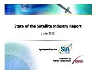
Radio-frequency (RF) intelligence, surveillance, <strong>and</strong><br />
reconnaissance: communication, early warning,<br />
safety assessment, <strong>and</strong> substantial cost reduction<br />
Bus-payload<br />
interface<br />
st<strong>and</strong>ard<br />
• Increases flexibility <strong>and</strong> responsiveness<br />
while obtaining a substantial cost reduction<br />
• Allows investment to occur from<br />
independent sources based on area of interest<br />
Electro-optical (EO) intelligence, surveillance, <strong>and</strong><br />
reconnaissance: imaging, missile warning, spectral sensing<br />
Prefabricated<br />
bus structure/<br />
SPA backplane<br />
Modular<br />
electronics<br />
Modular filter<br />
assembly<br />
Modular focal<br />
plane assembly<br />
Multifunction<br />
telescope<br />
PnP EO<br />
payload<br />
Modular<br />
propulsion<br />
Modular bus <strong>and</strong> modular payloads enable a reconfigurable architecture. re.<br />
This diagram illustrates a flow of common components for multiple missions that<br />
consolidates processes based on physics (i.e., radio frequency, optical, <strong>and</strong> bus).<br />
Common processes reduce personnel <strong>and</strong> equipment overheads <strong>and</strong> enable<br />
increased efficiency for a more rapid response over time.<br />
that can rapidly integrate <strong>and</strong> launch on<br />
the Minotaur 1, Minotaur 4, or Falcon 1E<br />
launch vehicles into either LEO or HEO<br />
orbits. A modular multimission bus architecture<br />
must be defined to support responsive<br />
operations through its ability to rapidly<br />
reconfigure (to the extent necessary) for the<br />
full range of ORS payload “mission kits”<br />
<strong>and</strong> orbits. A multimission bus that maximizes<br />
reuse of common core components in<br />
common configurations is a multiplier for<br />
RRSW operations as it maximizes the reuse<br />
of assembly, integration, <strong>and</strong> test equipment<br />
<strong>and</strong> procedures, thus reducing timelines,<br />
inventories, personnel, maintenance, <strong>and</strong><br />
training.<br />
The ORS Office has adopted two major<br />
bodies of work as input to its st<strong>and</strong>ards<br />
activities. The first is a body of st<strong>and</strong>ards<br />
developed by the Integrated <strong>Systems</strong> Engineering<br />
Team (ISET); commissioned<br />
by the Office of the Secretary of Defense,<br />
Office of Force Transformation in 2005 to<br />
produce an optimized set of performance<br />
requirements <strong>and</strong> st<strong>and</strong>ards for meeting<br />
potential ORS missions. The second is the<br />
<strong>Space</strong> Plug <strong>and</strong> Play Avionics (SPA) st<strong>and</strong>ards<br />
developed by the Air Force Research<br />
Laboratory. The ISET st<strong>and</strong>ards specified<br />
a generic one-bus-fits-all description in<br />
addressing the maximum number of ORS<br />
missions. Meeting the full range of ORS<br />
missions, however, requires adjusting the<br />
ISET st<strong>and</strong>ards to a modular <strong>and</strong> reconfigurable<br />
multimission bus. The SPA architecture<br />
<strong>and</strong> st<strong>and</strong>ards enable this additional<br />
level of modularity for responsive operations<br />
by addressing the full spectrum of<br />
ORS missions. As a result, the ORS Office<br />
is working to incorporate <strong>and</strong> demonstrate<br />
the SPA st<strong>and</strong>ards within the existing ISET<br />
definition to produce a validated ORS multimission<br />
bus architecture.<br />
The SPA architecture with its Satellite<br />
Data Model manages the self-discovery<br />
of SPA-enabled hardware <strong>and</strong> software<br />
components, much like the way personal<br />
computers recognize <strong>and</strong> configure USB<br />
components <strong>and</strong> peripherals. Self-discovery<br />
provides a means to rapidly assemble or<br />
reconfigure satellite systems. Each SPAenabled<br />
component is described by an<br />
XML-expressed data sheet, called the<br />
“extensible Transducer Electronic Data<br />
Sheet” (xTEDS). The TEDS st<strong>and</strong>ard was<br />
originally created by the IEEE 1451 st<strong>and</strong>ards<br />
group as a means of storing device<br />
descriptions within each individual device.<br />
The xTEDS uses both XML <strong>and</strong> TEDS<br />
st<strong>and</strong>ards to provide a structured way to<br />
describe the features, actions, <strong>and</strong> services<br />
(data, comm<strong>and</strong>s, interfaces, <strong>and</strong> requirements)<br />
of each SPA-enabled component.<br />
The SPA architecture employs an IP-based<br />
protocol to route messages point-to-point<br />
between SPA-compliant components using<br />
the widely accepted <strong>Space</strong>Wire transport<br />
st<strong>and</strong>ard. It will also register components<br />
(both hardware <strong>and</strong> software) along with<br />
their capabilities within a common database<br />
so that any spacecraft component or external<br />
system can query that repository for<br />
specific characteristics <strong>and</strong> then subscribe<br />
to that component’s capability or service. A<br />
similar model is under development by the<br />
Consultative Committee for <strong>Space</strong> Data<br />
<strong>Systems</strong> (CCSDS) called the <strong>Space</strong>craft<br />
On-board Interface Services. NASA <strong>and</strong><br />
Crosslink Summer 2009 • 15