Rolling Contact Fatigue mitigation by grinding - speno international sa
Rolling Contact Fatigue mitigation by grinding - speno international sa
Rolling Contact Fatigue mitigation by grinding - speno international sa

Create successful ePaper yourself
Turn your PDF publications into a flip-book with our unique Google optimized e-Paper software.
ROLLING CONTACT FATIGUE MITIGATION BY GRINDING<br />
Dr. Wolfgang Schoech<br />
Manager External Affaires, Speno International SA<br />
26, Parc Château Banquet, CH - 1211 Geneva 21, Switzerland<br />
Tel: +41 22 9064600<br />
Fax: +41 22 9064601<br />
e-mail: WS@<strong>speno</strong>.ch<br />
1. INTRODUCTION<br />
Today rail <strong>grinding</strong> has become a standard maintenance activity. The benefits of this operation are<br />
well known. Various <strong>grinding</strong> applications exist depending on local conditions. The treatment is related<br />
to the railhead’s longitudinal profile, its cross-sectional profile, or the surface condition of the wheel-torail<br />
zone (or possibly a combination of these parameters).<br />
Rail surface fatigue has become a widespread phenomenon. Originally mainly a topic for heavy haul<br />
railways, it is now a worldwide concern for conventional mixed-traffic railroads and in particular for<br />
high-speed lines with commercial speeds above 200 km/h.<br />
Excessive stresses in the rail result mainly from the interface conditions between the wheel and the<br />
rail. There is no doubt that large dynamic forces are generated at higher train speeds. <strong>Contact</strong> forces<br />
from the powerful acceleration of motorized axles amplify surface stresses in the wheel-to-rail contact<br />
zone. To keep these forces to a minimum it is essential to control the shapes of the two components.<br />
As infrastructure operators have little influence on the wheel profiles, their only solution is to establish<br />
optimal rail-head profiles and remove the fatigued surface layers as they form in service.<br />
This result can be achieved <strong>by</strong> rail maintenance through <strong>grinding</strong>. Recently, special railhead profiles -<br />
different from the as-rolled ones - have been developed for this purpose. Most rail <strong>grinding</strong><br />
interventions are well served <strong>by</strong> tight tolerances as the wheel-to-rail interaction is exceptionally<br />
sensitive. In the case of combating surface fatigue, the selection of <strong>grinding</strong> parameters is particularly<br />
difficult. As the defect is in the subsurface and of a metallurgical nature, its dimension is hard to grasp.<br />
Furthermore, knowledge of headcheck development is incomplete. The small physical symptoms do<br />
not reveal how far the failure mechanism has progressed in terms of rail integrity. For these reasons,<br />
in the absence of means to measure the threat, surface fatigue <strong>grinding</strong> is largely determined <strong>by</strong> a<br />
cyclical approach that may, or may not, be optimal.<br />
In Europe the railways are in the process of establishing <strong>grinding</strong> strategies and specifications for<br />
maintenance work that aim at reducing surface fatigue. Up to now <strong>grinding</strong> campaigns to reduce<br />
fatigue were specified only <strong>by</strong> stating the number of <strong>grinding</strong> passes to be executed at the gauge<br />
corner. In some cases the surface fatigue factor was neglected completely and rails were changed<br />
through <strong>sa</strong>fety considerations.<br />
Now, from thorough investigations that have taken place in recent years maintenance strategies and<br />
specifications for surface fatigue <strong>grinding</strong> are under development.<br />
2. ROLLING CONTACT FATIGUE<br />
As mentioned, the rail steel may pass its fatigue limit when subjected to high dynamic forces or when<br />
the loaded zone is comparatively small. This situation happens particularly on the high rails in curves,<br />
where all wheel-sets position themselves for free curving for a given rolling radius differential.
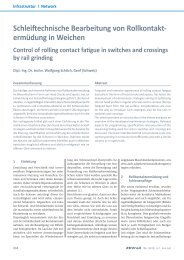
2.1 Headchecks<br />
In these conditions surface fatigue occurs and fine hairline surface cracks appear. If untreated, the<br />
cracks continue to grow - sometimes outwards to create flaking and spalling, sometimes downwards to<br />
lead to possible rail breakage.<br />
In tangent track the contact zone is situated more or less in the centre of the railhead. Sometimes<br />
isolated surface cracks appear that extend below and parallel to the rail surface. These cracks can<br />
develop into so-called squats or black spots. They may occasionally turn down vertically and finally<br />
result in a complete rail break. When rails are ground in fixed cycles such defects are removed in an<br />
early stage and therefore in principle do not give rise to catastrophic failures.<br />
Figure 1: Headchecks at gauge corner<br />
2.2 Squats<br />
Squats are another effect caused <strong>by</strong> fatigue. Similar to headchecks they appear in tangent track and<br />
very shallow curves anywhere in the contact zone from centre to gauge. Sometimes they are related<br />
to corrugation or imprints on the surface. Looking like a half-circle of v-shaped cracks on the surface<br />
they propagate a few tenths of a millimeter under the surface in the longitudinal direction and turn<br />
occasionally downwards. Due to the subsurface crack the contact zone shifts to either side of the<br />
affected spot, which increases local loading and accelerates further crack growth.<br />
Single squats can be repaired <strong>by</strong> welding. Accumulation of squats requires rail change. Their<br />
occurrence can only be prevented <strong>by</strong> timely removal of the fatigue surface layer <strong>by</strong> <strong>grinding</strong>.<br />
Figure 2: Squats<br />
2.3 Belgrospi<br />
On rails affected <strong>by</strong> short pitch corrugation another fatigue phenomenon has been observed. On the<br />
crests a network of cracks appears, a sort of mixture of irregular headchecks and small squats, with<br />
the <strong>sa</strong>me risk of consequent severe damage. First detected on a German high-speed-line <strong>by</strong> three<br />
engineers named Belz, Grohmann and Spiegel they are known as “Belgrospi’s”. It has been found that
0.03 mm deep short pitch corrugation can increase the dynamic forces sufficiently to develop this kind<br />
of defect.<br />
Figure 3: Belgrospi<br />
3. APPLICATION OF GRINDING<br />
Rail <strong>grinding</strong> intervenes at the rail surface essentially <strong>by</strong> removing metal. Irregularities in the<br />
longitudinal plane (corrugation) or the surface (imprints) are there<strong>by</strong> eliminated. In the <strong>sa</strong>me manner<br />
fatigued material at the rail surface is taken off. Depending on the damage depth, more or less<br />
material needs to be ground off in order to expose fresh material to the rolling wheels. To keep contact<br />
stresses at low levels, appropriate target profiles have to be applied.<br />
3.1 Transverse profile<br />
The interaction between wheel and rail is important for two reasons – it determines the transmission of<br />
large forces within a small zone, and also ensures wheel guiding stability. If the railhead geometry<br />
does not fit optimally to the wheel tread geometry, contact stresses may exceed material fatigue limits.<br />
The result, sooner or later, will be surface cracks on the rail (usually referred to as “headchecks”).<br />
Even with new track, surface conditions are not always perfect. Tolerances (rail shape, fastenings etc.)<br />
may cumulate towards a negative situation. Modern rails, particularly head hardened ones, have a<br />
very low wear rate, almost close to zero. Consequently their shape does not adapt quickly to the ideal<br />
profile. Thus, initial <strong>grinding</strong> of new lines is now common in order to provide optimal contact conditions<br />
from the very beginning. Simultaneously, imperfections in the longitudinal profiles, such as damage<br />
from construction activities, ballast stone imprints or irregularities around welds can be corrected.<br />
3.1.1 Anti-headcheck profiles<br />
To delay fatigue an appropriate railhead shape is required that keeps the contact zone away from the<br />
sensitive gauge shoulder area (until the natural wear process brings it back). Gauge corner<br />
undercutting has been executed on heavy haul railways for some time. In the case of higher speed<br />
traffic, there is a reluctance to modify the standard profile. However, production tolerances of around<br />
+ / - 0.3 mm at the gauge corner are commonly specified.<br />
In order to prescribe appropriate contact conditions several railways have developed specific profiles,<br />
providing clearance between wheel flange and gauge corner. Depending on the local situation<br />
different profile shapes have been designed. Up to one millimetre gauge corner relief can be found.<br />
These so-called anti-headcheck profiles have proven beneficial. Another possibility to overcome heavy<br />
gauge corner contact is to allow only negative tolerances to the standard target profile.<br />
3.1.2 High-speed profiles<br />
At increased speeds, trains react more sensitively to any lateral irregularity, the controlling parameter<br />
being the “equivalent conicity”. The influences from the track on this parameter are the rail profiles, the
ail inclination and the gauge width. For line speeds above 200 km/h appropriate values of equivalent<br />
conicity are between 0,05 and 0.3. To ensure smooth self-centring of the wheelsets in tangent track,<br />
gauge should be kept relatively wide. In this way lateral oscillations are smoothed out and unstable<br />
running conditions, often referred to as hunting, do not occur. Lateral running stability can be improved<br />
<strong>by</strong> providing a wider gauge width.<br />
Applying high-convexity rail profiles, which assure a lower equivalent conicity, is an approved<br />
alternative. Austrian Federal Railways (ÖBB) have developed such a particular target profile for highspeed<br />
lines for tangent track and shallow curves. By using a 130 mm crown radius, a 60 mm shoulder<br />
radius and a 22 mm gauge radius this profile provides ideal conditions for high speed running and<br />
reduces at the <strong>sa</strong>me time the risk of gauge corner fatigue.<br />
[mm]<br />
-30,00<br />
UIC 60<br />
CONVEX PROFILE<br />
-35,00<br />
-40,00<br />
-45,00<br />
-50,00<br />
-55,00<br />
-60,00<br />
UIC 60 inclined 1/40<br />
Convex Profile Type ÖBB<br />
inclined 1/40<br />
Standard <strong>grinding</strong> profile<br />
Anti-headcheck-profile (moderate)<br />
Anti-headcheck-profile (pronounced)<br />
-65,00<br />
-70,00<br />
-40 -35 -30 -25 -20 -15 -10 -5 0 5 10 15 20 25 30 35 40 45<br />
[mm]<br />
Figure 2 (left): Low – conicity - profile<br />
Figure 3 (above): Anti-headcheck-profiles<br />
3.2 German headcheck study<br />
An interesting project <strong>by</strong> German Railways (DB AG) has been concluded recently. This project was<br />
launched already in 1995 to investigate the influence of tolerances for production <strong>grinding</strong> on<br />
headcheck development. Speno International participated in the project from the beginning as the<br />
contractor executing the <strong>grinding</strong> work to DB specifications.<br />
A very pragmatic approach was chosen: Several test sections in curves with similar traffic and track<br />
characteristics were selected. On these zones the fatigue defects were removed completely and their<br />
re-development monitored after having shaped the railheads in different, well-defined ways.<br />
The test sites were situated near Würzburg on the Frankfurt - Würzburg route. On two of the sites<br />
standard rail steel of grade R260 (formerly 900A) were installed, the other two sites had headhardened<br />
rails of grade R350HT (formerly 900A HH). All sites were typical surface fatigue locations<br />
with rather new rails already affected <strong>by</strong> headchecks, though not too severely. The curves there had<br />
different radii, as it was not possible to find curves with identical track parameters. The chosen four<br />
test curves contained in total 20 test sections, each 100 meters long.<br />
This first part of the research work dealt with target profiles and production tolerances. The main<br />
findings were:<br />
• Surface fatigue develops at a lower pace with head-hardened rails<br />
• The standard target profile for <strong>grinding</strong> is very close to the wear-adapted profile, which is<br />
favourable with respect to development of fatigue<br />
• However, positive profile tolerances are of adverse influence, that is they increase the<br />
development of surface fatigue<br />
• Negative tolerances (undercutting of the gauge corner) decrease the development of head checks<br />
• A smooth <strong>grinding</strong> finish is preferable, sharp edges between <strong>grinding</strong> facets should be avoided<br />
Following the test experience, and as a first intermediate result, DB has adapted the specifications for<br />
<strong>grinding</strong> work, <strong>by</strong> stating that for headchecked rail in curves only negative tolerances up to -0.6 mm<br />
are acceptable.
The second project phase concentrated on finding the most appropriate <strong>grinding</strong> cycle and metal<br />
removal rate. Metal removal <strong>by</strong> <strong>grinding</strong> equates to artificial wear, and gauge corner undercutting<br />
increases traffic-related wear. Both mechanisms determine rail withdrawals (i.e. fatigue and wear) and<br />
have therefore to be well balanced.<br />
The aim of an optimized <strong>grinding</strong> strategy is to remove as much metal as neces<strong>sa</strong>ry for fatigue control<br />
but as little as possible over the whole rail life span in order to minimize wear. The combined<br />
knowledge of crack growth and wear development (both naturally <strong>by</strong> traffic and artificially <strong>by</strong> <strong>grinding</strong>)<br />
finally allows prolongation of rail service life to a maximum.<br />
An optimal <strong>grinding</strong> strategy should aim at optimal profiling cycles with minimal metal removal and<br />
wear. Comparison of wear over three-monthly intervals allowed prediction of wear development.<br />
Several <strong>grinding</strong> cycles (one to four years) have been tested in order to provide sufficient data for<br />
analysis.<br />
The conclusions - drawn from the test results and the recommendations for specifications for rail<br />
<strong>grinding</strong> work - can be summarized as follows:<br />
Surface fatigue can be effectively controlled <strong>by</strong> strategic rail maintenance. First priority is knowledge of<br />
the actual severity of the problem. Despite a recently developed recording system <strong>by</strong> eddy current, the<br />
severity and, more importantly, the growth rate of cracks is largely unknown. There is unanimous<br />
opinion that the complete absence of cracks is the optimal solution. This is not a problem for small<br />
cracks which are completely removed. However, deeper cracks should also be removed, as the<br />
behaviour of partially removed cracks is not clear, due to different crack angles, widths and depths.<br />
As has been found, the smaller the defects the more uniform they are, so smaller cracks can be<br />
treated more efficiently. Also, heavy undercutting of the gauge corner defers fatigue development but<br />
increases wear. Thus it follows that shorter <strong>grinding</strong> cycles are better, as the defects are smaller and<br />
less undercutting is required.<br />
3.3 Grinding strategies<br />
At present three stages can be identified for setting up rail maintenance:<br />
3.3.1 Preventive actions<br />
Such actions can be used in all cases where defects are not yet detectable, but are assumed to<br />
develop from previous experience. Furthermore this approach should be considered where previous<br />
knowledge of defect growth indicates that their depths will remain small, <strong>sa</strong>y well below 0.2 mm during<br />
subsequent <strong>grinding</strong> interventions. Preventive action also should be applied initially, when rails are<br />
new or have been in service for a few weeks only.<br />
Grinding work can be specified as follows:<br />
• Metal removal over the whole rail head of up to 0.2 mm<br />
• The target profile should be the wear-adapted one with only small negative tolerances<br />
Consequence for maintenance work:<br />
• Frequent and light interventions,<br />
• Frequent traffic disturbance and cumulative high, but predictable, artificial wear<br />
3.3.2 Cyclical actions<br />
Preventive action is only suitable for initial <strong>grinding</strong> of new rails. However, cracks in their early stage<br />
are not a <strong>sa</strong>fety risk as they are not likely to develop too quickly into a serious problem. Thus <strong>grinding</strong><br />
can achieve small-to-medium metal removal rates very effectively (with a relatively high production<br />
rate), particularly when the work is concentrated on the zone close to the gauge corner where negative<br />
tolerances can be accepted.
This approach allows controlled <strong>grinding</strong> cycles that balance crack growth, metal removal and<br />
maintenance intervals in an acceptable compromise that is advantageous.<br />
Grinding work can be specified as follows:<br />
• Metal removal in fatigued zone to a depth between 0.2 and 0.6 mm<br />
• Target profile (wear-adapted) within acceptable tolerances (-0.6 mm maximum)<br />
With modern <strong>grinding</strong> equipment complete headcheck removal is possible. Bigger machines can effect<br />
even one-pass-<strong>grinding</strong> with production rates that reduce traffic disturbances and artificial wear. Onboard<br />
headcheck measuring systems is required to control exactly the defect elimination while limiting<br />
metal removal.<br />
3.3.3 Corrective actions<br />
Of course it is not possible to grind all new rails, and <strong>grinding</strong> cycles cannot always be programmed to<br />
avoid more severe defect situations. Thus when starting a campaign many kilometers of track may be<br />
in different stages of fatigue from medium to very severe.<br />
In these cases, apart from changing rails heavily affected <strong>by</strong> fatigue, corrective <strong>grinding</strong> may prove<br />
economically justified. Rails with completely removed headchecks can serve for another long period,<br />
provided that there is a subsequent series of cyclical interventions.<br />
Grinding work can be specified as follows:<br />
• Metal removal from 0.6 mm up to 3 mm (estimated maximum value for economic reasons)<br />
• Wear-adapted target profile with only negative tolerances (-1.0 mm maximum)<br />
Heavy duty <strong>grinding</strong> equipment is recommended in order to limit the number of <strong>grinding</strong> passes.<br />
Milling and planing can provide useful alternatives. Monitoring of crack depths should be available to<br />
check that cracks are completely removed. If cracks cannot be completely removed in one intervention<br />
due to limited track possession time, a gradual corrective approach can be envi<strong>sa</strong>ged, with<br />
subsequent corrective actions planned well before defect growth deteriorates again.<br />
3.3.4 Recommended actions<br />
As all <strong>grinding</strong> strategies depend on many parameters, only guide-lines can be given. Actions will<br />
depend on local traffic and track characteristics that influence fatigue development together with<br />
operational aspects.<br />
In a simplified summary: a controlled <strong>grinding</strong> action is best when the process can remove in a onepass-action<br />
just the existing defect depth while simultaneously correcting the transverse profile.<br />
As a representative figure, a cyclical metal removal, of 0.3 to 0.4mm (corresponding to some 30 to<br />
40 MGT for rail grade R260, or every second year on an average conventional line) can be expected.<br />
As harder rails show a reduced fatigue development the <strong>grinding</strong> intervals may be respectively longer,<br />
while maintaining the <strong>sa</strong>me metal removal rates.<br />
3.4 Grinding rails in turnouts<br />
Surface fatigue concerns not only on open track but in turnouts as well. Track components there are<br />
particularly sensitive to surface damage. Running from stock-rails to switch blades and over frogs,<br />
usually mobile ones, always implies higher dynamic forces and lateral movements. Squats on swing<br />
nose frogs and headchecks on turnout rails have been observed frequently.<br />
Many railways have adopted rail <strong>grinding</strong> in turnouts. Of particular importance is to maintain the ideal<br />
railhead profile also over the turnout area. As-inclined railhead profiles on vertically mounted rails are<br />
standard today. Even anti-headcheck profiles in switches have been tested successfully.
3.5 Recording<br />
In the last few years a newly developed method of non-destructive testing for cracks and surface<br />
defects based on eddy-current technology has made possible the checking of crack propagation<br />
throughout the entire length of track affected <strong>by</strong> rolling contact fatigue.<br />
Recently such automated in-track eddy current testing systems (known as Headcheck Grinding<br />
Scanner) have been installed <strong>by</strong> Speno International for the first time on <strong>grinding</strong> machines. This<br />
equipment allows checking and documenting of crack removal continuously during <strong>grinding</strong> work.<br />
Figure 4: Headcheck Grinding Scanner - Results: Before (top) and after (bottom) <strong>grinding</strong><br />
4. CONCLUSION<br />
By removing surface cracks and keeping the rail profile in good shape the <strong>sa</strong>fety-relevant fatigue<br />
problem is converted to a simple wear management issue. Rail renewal depends then on reaching the<br />
well-known wear limits, whereas fatigue limits are not so easy to define.<br />
Grinding rails is a very complex matter and must always be seen from technical, operational and<br />
economical points of view. A technically perfect solution does not make sense if it is not economically<br />
justified or to too complicated to be put in practice. Removing too much metal, or in an inappropriate<br />
way, to avoid surface fatigue problems could result in much metal loss and premature rail withdrawal<br />
due to wear.<br />
Research work and experience over long periods allow the definition of criteria to minimize surface<br />
fatigue damage and extend rail service life through three types of <strong>grinding</strong> actions - initial, cyclical and<br />
corrective. The best approach with new rails is an initial <strong>grinding</strong> followed <strong>by</strong> cyclically controlled<br />
actions. For rails in track already showing surface fatigue a corrective action followed <strong>by</strong> cyclically<br />
controlled <strong>grinding</strong> offers the best solution.<br />
It is recommended to program the <strong>grinding</strong> actions when surface fatigue is present in an early stage<br />
and metal removal is below 0.6 mm. Taking into account operational aspects, an average rate of a<br />
<strong>grinding</strong> intervention every 25 to 50 MGT should be envi<strong>sa</strong>ged.
A newly available recording system for monitoring headcheck elimination during <strong>grinding</strong> allows<br />
effective control of surface fatigue while minimizing metal loss <strong>by</strong> artificial wear. Practical application of<br />
the proposed strategies will help to fine-tune specifications for <strong>grinding</strong> according to local conditions.<br />
REFERENCES<br />
[1] W. Schoech and R. Heyder: Rail Surface <strong>Fatigue</strong> and Grinding: Exploring the Interaction,<br />
Proceedings of the 6th International Conference on <strong>Contact</strong> Mechanics and Wear of Rail/Wheel<br />
Systems, Gothenburg, 2003, pp. 133-138.<br />
[2] W.Schoech, R. Heyder, H.D. Grohmann: <strong>Contact</strong> Geometry And Surface <strong>Fatigue</strong> –<br />
Guidelines For Appropriate Rail Maintenance, Proceedings of the 7th International Conference on<br />
<strong>Contact</strong> Mechanics and Wear of Rail/Wheel Systems, Brisbane, 2006.<br />
[3] R. Krull, H. Hintze, M. Thomas, R. Pohl and S. Ruehe: Eddy-current Detection of Head<br />
Checks on the Gauge Corner of Rails: Recent Results, Proceedings of the 6th International<br />
Conference Railway Engineering, London, 2003.<br />
¨