EDID Manager User's Manual - Eavs
EDID Manager User's Manual - Eavs
EDID Manager User's Manual - Eavs
Create successful ePaper yourself
Turn your PDF publications into a flip-book with our unique Google optimized e-Paper software.
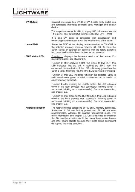
DVI Output<br />
Learn <strong>EDID</strong><br />
<strong>EDID</strong> status LED<br />
Address selection<br />
Connect one single link DVI-D or DVI-I cable (only digital pins<br />
are connected internally) between <strong>EDID</strong> <strong>Manager</strong> and display<br />
device.<br />
The output connector is able to supply 500 mA current on pin<br />
14 to power fiber optical DVI extenders like DVI-OPT-TX100.<br />
If a long DVI cable is connected then equalization and<br />
reclocking may be necessary at the receiver end of the cable.<br />
Stores the <strong>EDID</strong> of the display device attached to DVI OUT in<br />
the selected memory address between 51…99. To learn the<br />
<strong>EDID</strong>, select an appropriate address with the rotary switches<br />
and press and hold the Learn button for two seconds.<br />
Function 1: displays the firmware version of the device. For<br />
more information, see chapter 2.1.<br />
Function 2: after applying a Hot Plug signal to DVI OUT, this<br />
LED indicates that the unit is reading the <strong>EDID</strong> from the<br />
connected display device. If the LED is blinking green then the<br />
<strong>EDID</strong> is valid, if blinking red, then the <strong>EDID</strong> is invalid or missing.<br />
Function 3: this LED indicates whether the selected <strong>EDID</strong> is<br />
valid (continuous green = valid, continuous red = invalid or<br />
empty memory selected).<br />
Function 4: after pressing the LEARN button, this LED indicates<br />
whether the learn process was successful (blinking green =<br />
successful, blinking red = unsuccessful). For more information,<br />
see chapter 2.2.<br />
Function 5: after pressing the BURN button, this LED indicates<br />
whether the burn process was successful (blinking green =<br />
successful, blinking red = unsuccessful). For more information,<br />
see chapter 2.5.<br />
The rotary switches select one of 100 <strong>EDID</strong> memory addresses.<br />
Addresses 1…50 are factory preset and 51…99 are user<br />
programmable. Address 00 enables transparent mode. For<br />
more information, see chapter 2.2. Use a flat head screwdriver<br />
that fits into the actuator. Avoid the use of keys, coins, knives<br />
and other sharp objects because they might cause permanent<br />
damage to the rotary switches.<br />
Page 10 / 19


