WindPRO / PARK - EMD International AS.
WindPRO / PARK - EMD International AS.
WindPRO / PARK - EMD International AS.

You also want an ePaper? Increase the reach of your titles
YUMPU automatically turns print PDFs into web optimized ePapers that Google loves.
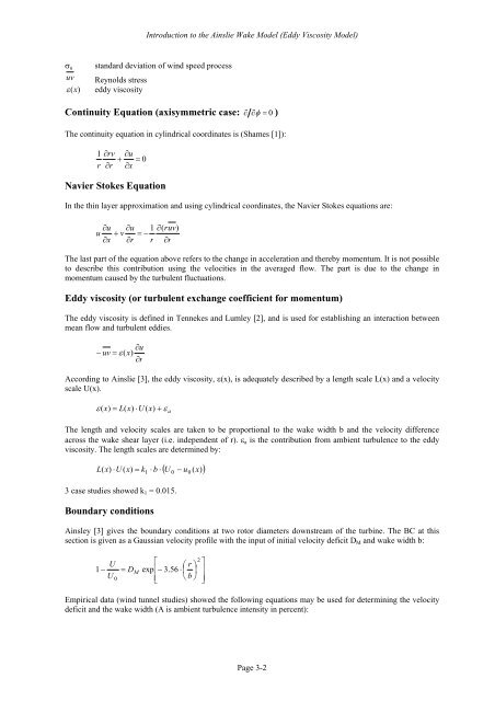
Introduction to the Ainslie Wake Model (Eddy Viscosity Model)<br />
σ u standard deviation of wind speed process<br />
uv Reynolds stress<br />
ε (x) eddy viscosity<br />
Continuity Equation (axisymmetric case: ∂ ∂φ = 0 )<br />
The continuity equation in cylindrical coordinates is (Shames [1]):<br />
1 ∂rv<br />
∂u<br />
+ = 0<br />
r ∂r<br />
∂x<br />
Navier Stokes Equation<br />
In the thin layer approximation and using cylindrical coordinates, the Navier Stokes equations are:<br />
u u ruv<br />
u<br />
∂ ∂ 1 ∂(<br />
+ v = −<br />
)<br />
∂x<br />
∂r<br />
r ∂r<br />
The last part of the equation above refers to the change in acceleration and thereby momentum. It is not possible<br />
to describe this contribution using the velocities in the averaged flow. The part is due to the change in<br />
momentum caused by the turbulent fluctuations.<br />
Eddy viscosity (or turbulent exchange coefficient for momentum)<br />
The eddy viscosity is defined in Tennekes and Lumley [2], and is used for establishing an interaction between<br />
mean flow and turbulent eddies.<br />
∂u<br />
− uv = ε ( x)<br />
∂r<br />
According to Ainslie [3], the eddy viscosity, ε(x), is adequately described by a length scale L(x) and a velocity<br />
scale U(x).<br />
ε ( x)<br />
= L(<br />
x)<br />
⋅U<br />
( x)<br />
+ ε<br />
a<br />
The length and velocity scales are taken to be proportional to the wake width b and the velocity difference<br />
across the wake shear layer (i.e. independent of r). ε a is the contribution from ambient turbulence to the eddy<br />
viscosity. The length scales are determined by:<br />
( U − u ( ))<br />
L( x)<br />
⋅ U ( x)<br />
= k ⋅ b ⋅ 0 0<br />
1 x<br />
3 case studies showed k 1 = 0.015.<br />
Boundary conditions<br />
Ainsley [3] gives the boundary conditions at two rotor diameters downstream of the turbine. The BC at this<br />
section is given as a Gaussian velocity profile with the input of initial velocity deficit D M and wake width b:<br />
1 −<br />
U<br />
U<br />
0<br />
= D<br />
M<br />
⎡ ⎛ r ⎞<br />
exp⎢−<br />
3.56 ⋅ ⎜ ⎟<br />
⎢⎣<br />
⎝ b ⎠<br />
2<br />
⎤<br />
⎥<br />
⎥⎦<br />
Empirical data (wind tunnel studies) showed the following equations may be used for determining the velocity<br />
deficit and the wake width (A is ambient turbulence intensity in percent):<br />
Page 3-2