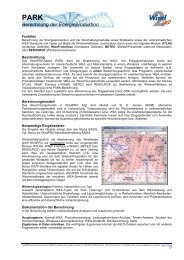
WindPRO / PARK - EMD International AS.
WindPRO / PARK - EMD International AS.
WindPRO / PARK - EMD International AS.

You also want an ePaper? Increase the reach of your titles
YUMPU automatically turns print PDFs into web optimized ePapers that Google loves.
Wake Combination Models<br />
5. Wake Combination Models<br />
Today (2005), most wake models are still single wake<br />
models. Thus, in order to obtain a usable result for wind<br />
farms with many turbines, these single wakes must be<br />
combined into a combined effect. This is done by purely<br />
empirical means, using different wake combination<br />
models.<br />
Introduction<br />
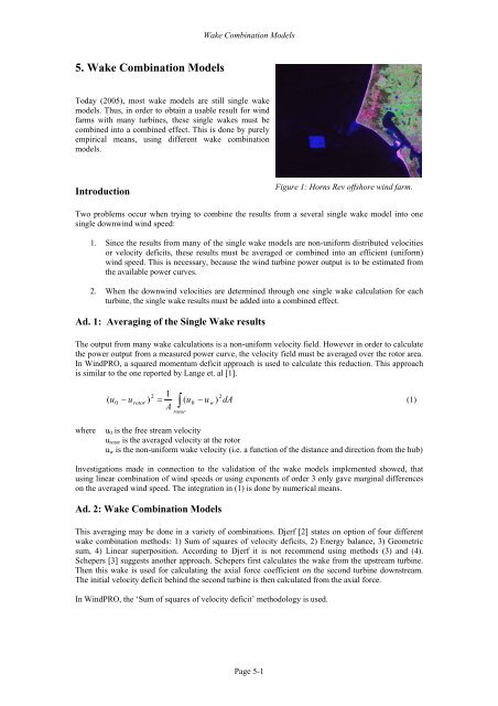
Figure 1: Horns Rev offshore wind farm.<br />
Two problems occur when trying to combine the results from a several single wake model into one<br />
single downwind wind speed:<br />
1. Since the results from many of the single wake models are non-uniform distributed velocities<br />
or velocity deficits, these results must be averaged or combined into an efficient (uniform)<br />
wind speed. This is necessary, because the wind turbine power output is to be estimated from<br />
the available power curves.<br />
2. When the downwind velocities are determined through one single wake calculation for each<br />
turbine, the single wake results must be added into a combined effect.<br />
Ad. 1: Averaging of the Single Wake results<br />
The output from many wake calculations is a non-uniform velocity field. However in order to calculate<br />
the power output from a measured power curve, the velocity field must be averaged over the rotor area.<br />
In <strong>WindPRO</strong>, a squared momentum deficit approach is used to calculate this reduction. This approach<br />
is similar to the one reported by Lange et. al [1].<br />
2 1<br />
2<br />
( u0 − urotor ) = u u w dA<br />
A ∫<br />
( 0 − )<br />
(1)<br />
rotor<br />
where<br />
u 0 is the free stream velocity<br />
u rotor is the averaged velocity at the rotor<br />
u w is the non-uniform wake velocity (i.e. a function of the distance and direction from the hub)<br />
Investigations made in connection to the validation of the wake models implemented showed, that<br />
using linear combination of wind speeds or using exponents of order 3 only gave marginal differences<br />
on the averaged wind speed. The integration in (1) is done by numerical means.<br />
Ad. 2: Wake Combination Models<br />
This averaging may be done in a variety of combinations. Djerf [2] states on option of four different<br />
wake combination methods: 1) Sum of squares of velocity deficits, 2) Energy balance, 3) Geometric<br />
sum, 4) Linear superposition. According to Djerf it is not recommend using methods (3) and (4).<br />
Schepers [3] suggests another approach. Schepers first calculates the wake from the upstream turbine.<br />
Then this wake is used for calculating the axial force coefficient on the second turbine downstream.<br />
The initial velocity deficit behind the second turbine is then calculated from the axial force.<br />
In <strong>WindPRO</strong>, the ‘Sum of squares of velocity deficit’ methodology is used.<br />
Page 5-1