Installation, Operation & Maintenance Manual - Corken
Installation, Operation & Maintenance Manual - Corken
Installation, Operation & Maintenance Manual - Corken

You also want an ePaper? Increase the reach of your titles
YUMPU automatically turns print PDFs into web optimized ePapers that Google loves.
Chapter 1—Installing Your <strong>Corken</strong> Compressor<br />
1.1 Location<br />
NOTE: Compressor must be installed in a well<br />
ventilated area.<br />
<strong>Corken</strong> compressors are designed and manufactured for<br />
outdoor duty. For applications where the compressor will<br />
be subjected to extreme conditions for extended periods<br />
such as corrosive environments, arctic conditions, etc.,<br />
consult <strong>Corken</strong>. Check local safety regulations and building<br />
codes to assure installation will meet local safety standards.<br />
Concrete foundation<br />
Note: The depth of the concrete foundation will<br />
vary based on local soil conditions.<br />
Hex nut<br />
&<br />
washer<br />
Main beam (C-Beam)<br />
Cross beam (H-Beam)<br />
<strong>Corken</strong> compressors handling toxic or flammable<br />
gases such as LPG/NH 3 should be located outdoors in<br />
a well ventilated area. A minimum of 18 inches (45 cm)<br />
clearance between the compressor and the nearest wall<br />
is advised to make it accessible from all sides and to<br />
provide unrestricted air flow for adequate cooling.<br />
Noise:<br />
<strong>Corken</strong> vertical compressors should not exceed an 85<br />
DBA noise level when properly installed.<br />
1.2 Foundation<br />
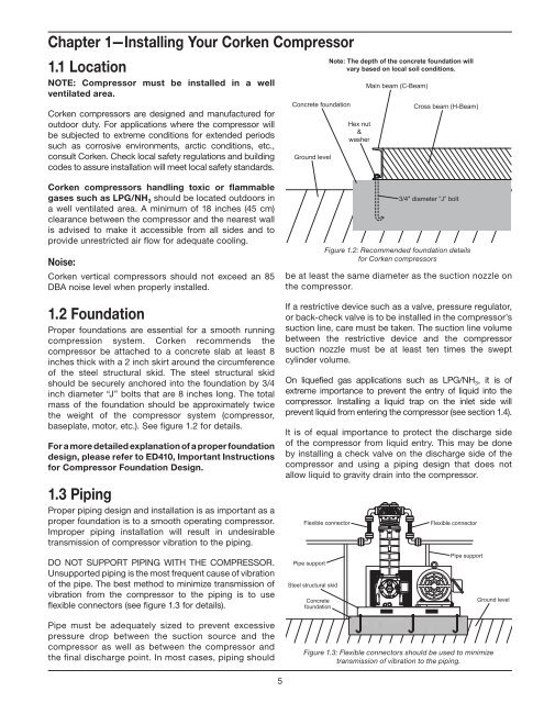
Proper foundations are essential for a smooth running<br />
compression system. <strong>Corken</strong> recommends the<br />
compressor be attached to a concrete slab at least 8<br />
inches thick with a 2 inch skirt around the circumference<br />
of the steel structural skid. The steel structural skid<br />
should be securely anchored into the foundation by 3/4<br />
inch diameter “J” bolts that are 8 inches long. The total<br />
mass of the foundation should be approximately twice<br />
the weight of the compressor system (compressor,<br />
baseplate, motor, etc.). See figure 1.2 for details.<br />
For a more detailed explanation of a proper foundation<br />
design, please refer to ED410, Important Instructions<br />
for Compressor Foundation Design.<br />
1.3 Piping<br />
Proper piping design and installation is as important as a<br />
proper foundation is to a smooth operating compressor.<br />
Improper piping installation will result in undesirable<br />
transmission of compressor vibration to the piping.<br />
DO NOT SUPPORT PIPING WITH THE COMPRESSOR.<br />
Unsupported piping is the most frequent cause of vibration<br />
of the pipe. The best method to minimize transmission of<br />
vibration from the compressor to the piping is to use<br />
flexible connectors (see figure 1.3 for details).<br />
Pipe must be adequately sized to prevent excessive<br />
pressure drop between the suction source and the<br />
compressor as well as between the compressor and<br />
the final discharge point. In most cases, piping should<br />
Figure 1.2: Recommended foundation details<br />
for <strong>Corken</strong> compressors<br />
be at least the same diameter as the suction nozzle on<br />
the compressor.<br />
If a restrictive device such as a valve, pressure regulator,<br />
or back-check valve is to be installed in the compressor’s<br />
suction line, care must be taken. The suction line volume<br />
between the restrictive device and the compressor<br />
suction nozzle must be at least ten times the swept<br />
cylinder volume.<br />
On liquefied gas applications such as LPG/NH 3 , it is of<br />
extreme importance to prevent the entry of liquid into the<br />
compressor. Installing a liquid trap on the inlet side will<br />
prevent liquid from entering the compressor (see section 1.4).<br />
It is of equal importance to protect the discharge side<br />
of the compressor from liquid entry. This may be done<br />
by installing a check valve on the discharge side of the<br />
compressor and using a piping design that does not<br />
allow liquid to gravity drain into the compressor.<br />
Flexible connector<br />
Pipe support<br />
Steel structural skid<br />
Concrete<br />
foundation<br />
3/4″ diameter “J” bolt<br />
Flexible connector<br />
Pipe support<br />
Ground level<br />
Figure 1.3: Flexible connectors should be used to minimize<br />
transmission of vibration to the piping.<br />
5