MINIDOS A - Lutz-Jesco Gmbh
MINIDOS A - Lutz-Jesco Gmbh
MINIDOS A - Lutz-Jesco Gmbh

You also want an ePaper? Increase the reach of your titles
YUMPU automatically turns print PDFs into web optimized ePapers that Google loves.
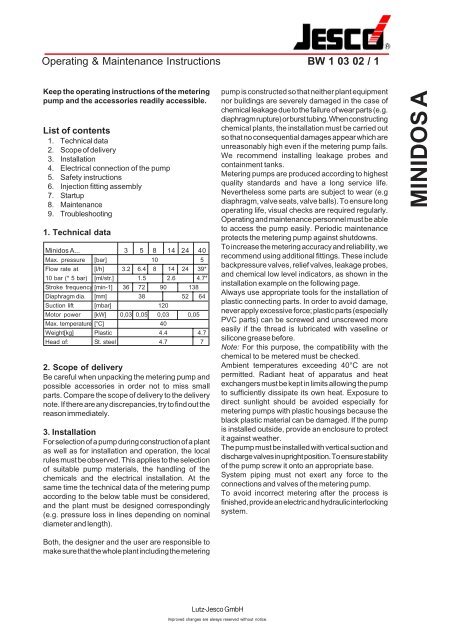
Operating & Maintenance Instructions<br />
BW 1 03 02 / 1<br />
Keep the operating instructions of the metering<br />
pump and the accessories readily accessible.<br />
List of contents<br />
1. Technical data<br />
2. Scope of delivery<br />
3. Installation<br />
4. Electrical connection of the pump<br />
5. Safety instructions<br />
6. Injection fitting assembly<br />
7. Startup<br />
8. Maintenance<br />
9. Troubleshooting<br />
1. Technical data<br />
Minidos A... 3 5 8 14 24 40<br />
Max. pressure [bar] 10 5<br />
Flow rate at [l/h] 3.2 6.4 8 14 24 39*<br />
10 bar (* 5 bar) [ml/str.] 1.5 2.6 4.7*<br />
Stroke frequency [min-1] 36 72 90 138<br />
Diaphragm dia. [mm] 38 52 64<br />
Suction lift [mbar] 120<br />
Motor power [kW] 0,03 0,05 0,03 0,05<br />
Max. temperature [°C] 40<br />
Weight[kg] Plastic 4.4 4.7<br />
Head of: St. steel 4.7 7<br />
2. Scope of delivery<br />
Be careful when unpacking the metering pump and<br />
possible accessories in order not to miss small<br />
parts. Compare the scope of delivery to the delivery<br />
note. If there are any discrepancies, try to find out the<br />
reason immediately.<br />
3. Installation<br />
For selection of a pump during construction of a plant<br />
as well as for installation and operation, the local<br />
rules must be observed. This applies to the selection<br />
of suitable pump materials, the handling of the<br />
chemicals and the electrical installation. At the<br />
same time the technical data of the metering pump<br />
according to the below table must be considered,<br />
and the plant must be designed correspondingly<br />
(e.g. pressure loss in lines depending on nominal<br />
diameter and length).<br />
pump is constructed so that neither plant equipment<br />
nor buildings are severely damaged in the case of<br />
chemical leakage due to the failure of wear parts (e.g.<br />
diaphragm rupture) or burst tubing. When constructing<br />
chemical plants, the installation must be carried out<br />
so that no consequential damages appear which are<br />
unreasonably high even if the metering pump fails.<br />
We recommend installing leakage probes and<br />
containment tanks.<br />
Metering pumps are produced according to highest<br />
quality standards and have a long service life.<br />
Nevertheless some parts are subject to wear (e.g<br />
diaphragm, valve seats, valve balls). To ensure long<br />
operating life, visual checks are required regularly.<br />
Operating and maintenance personnel must be able<br />
to access the pump easily. Periodic maintenance<br />
protects the metering pump against shutdowns.<br />
To increase the metering accuracy and reliability, we<br />
recommend using additional fittings. These include<br />
backpressure valves, relief valves, leakage probes,<br />
and chemical low level indicators, as shown in the<br />
installation example on the following page.<br />
Always use appropriate tools for the installation of<br />
plastic connecting parts. In order to avoid damage,<br />
never apply excessive force; plastic parts (especially<br />
PVC parts) can be screwed and unscrewed more<br />
easily if the thread is lubricated with vaseline or<br />
silicone grease before.<br />
Note: For this purpose, the compatibility with the<br />
chemical to be metered must be checked.<br />
Ambient temperatures exceeding 40°C are not<br />
permitted. Radiant heat of apparatus and heat<br />
exchangers must be kept in limits allowing the pump<br />
to sufficiently dissipate its own heat. Exposure to<br />
direct sunlight should be avoided especially for<br />
metering pumps with plastic housings because the<br />
black plastic material can be damaged. If the pump<br />
is installed outside, provide an enclosure to protect<br />
it against weather.<br />
The pump must be installed with vertical suction and<br />
discharge valves in upright position. To ensure stability<br />
of the pump screw it onto an appropriate base.<br />
System piping must not exert any force to the<br />
connections and valves of the metering pump.<br />
To avoid incorrect metering after the process is<br />
finished, provide an electric and hydraulic interlocking<br />
system.<br />
<strong>MINIDOS</strong> A<br />
Both, the designer and the user are responsible to<br />
make sure that the whole plant including the metering<br />
<strong>Lutz</strong>-<strong>Jesco</strong> GmbH<br />
Improved changes are always reserved without notice.
BW 1 03 02 / 2<br />
Installation example<br />
4. Electrical connection of the pump<br />
- The electrical connection of the pump must be<br />
made according to the local rules and may only be<br />
carried out by technical personnel.<br />
- Cable type and cable cross section of the supply<br />
lines must be selected according to the motor<br />
data.<br />
- The cable passage to the motor terminal box must<br />
be made professionally. We recommend gland<br />
screw connections with traction relief.<br />
- The required protection class mut be ensured by<br />
professional installation of the electrical<br />
connections.<br />
<strong>MINIDOS</strong> A<br />
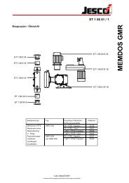
Legend<br />
1 Minidos A MB 1 03 02<br />
2 Suction line MB 1 22 01<br />
3 Electric agitator MB 1 36 03<br />
4 Tank MB 1 20 01<br />
5 Relief valve MB 1 25 01<br />
6 Diaphragm shutoff valve MB 1 24 01<br />
7 Injection nozzle MB 1 23 01<br />
8 Pulsation dampener MB 1 27 01<br />
9 Switch box<br />
Drain pipe<br />
Electrical connection data<br />
Pump Voltage Power Current<br />
model [Volt] [Watt] [A]<br />
A3, A8, A14 400/230 30 0.23/0.40<br />
A5,A24,A40 50 Hz 50 0.30/0.52<br />
A3, A8, A14 440/254 40 0.24/0.42<br />
A5, A24,A40 60 Hz 60 0.30/0.52<br />
A3, A8, A14 400/230 40 0.22/0.38<br />
A5, A24,A40 60 Hz 60 0.29/0.50<br />
A3, A8, A14 230/1~ 25 0.35<br />
A5, A24,A40 50 Hz 50 0.45<br />
Wiring diagram of the drive motor<br />
- 3-phase supply<br />
Collecting funnel<br />
The drainage or leakage must be run from the<br />
separating chamber downwards to the containment<br />
tank. By no means must the drain pipe be returned<br />
to the medium directly through the tank cover since<br />
otherwise effervescent media might enter the pump<br />
gear. The drain pipe must only be routed into a<br />
collecting tank free of gases (with a downward slope),<br />
or to a collecting funnel - also with a downward slope<br />
- above which the pipe ends at a sufficient distance.<br />
Leakage can then be returned via the funnel through<br />
the tank cover. Furthermore, any existing leakage<br />
can be seen at the collecting funnel.<br />
<strong>Lutz</strong>-<strong>Jesco</strong> GmbH<br />
Y-connection<br />
Improved changes are always reserved without notice.<br />
∆-connection<br />
- A.C. power supply with motor in Steinmetz<br />
connection<br />
Clockwise rotation Counter-clockwise<br />
rotation<br />
- Special versions<br />
For other special versions please refer to the<br />
corresponding separate circuit diagrams.<br />
- Electrical servomotor ATE<br />
The technical data and wiring diagrams are shown<br />
on pages BW 1 03 02 / 7-10.
BW 1 03 02 / 3<br />
5. Safety instructions<br />
⇒ When working on chemical equipment, observe<br />
the local safety rules (e.g. wear personal protective<br />
clothes).<br />
⇒ Before working on the metering pump and plant,<br />
disconnect it from the main power supply and secure<br />
it against reconnection. Before the voltage supply is<br />
switched on again, the metering lines must be<br />
connected so that chemical left in the metering head<br />
cannot spurt out.<br />
⇒ The metering head of the pump as well as<br />
connections and lines in the plant may be under<br />
pressure. Working on the metering plant requires<br />
special safety precautions and may only be carried<br />
out by instructed technical personnel.<br />
⇒ Before startup, all screwed connections must be<br />
checked for correct tightness and, if necessary,<br />
must be tightened up using appropriate tools.<br />
⇒ If connections at the metering head are unscrewed<br />
during operation for venting or other reasons, leaking<br />
chemical must be removed completely. This is the<br />
only way to avoid the danger of physical injury and<br />
corrosion at the metering pump. Leaking chemical<br />
may also destroy the diaphragm at its mounting<br />
points.<br />
⇒ When changing the chemical, check whether the<br />
materials used for the metering pump and the other<br />
plant parts are chemically resistant.<br />
If there is the danger of a chemical reaction between<br />
different media, a thorough cleaning first is mandatory.<br />
⇒ The base area of the pump must be kept free to<br />
ensure sufficient air circulation for cooling of the<br />
motor. If liquid is likely to accumulate below the pump<br />
base, install the pump at a higher position.<br />
6. Injection fitting assembly<br />
Injection nozzles prevent the liquid from returning to<br />
the pump by using either a spring-loaded ball valve or<br />
a hose valve. We recommend injection from bottom<br />
to top to allow air to escape thereby avoiding chemical<br />
precipitation. Experience with the particular metering<br />
chemical and all appropriate characteristics must be<br />
taken into account.<br />
Injection<br />
nozzle<br />
7. Startup<br />
1. Before starting the metering pumps all works<br />
mentioned in section 3 "Installation" must be<br />
carried out. At the same time the safety<br />
instructions must be observed.<br />
2. The metering pump is switched on by a control<br />
to be installed externally.<br />
3. The manual or electrical capacity adjustment<br />
must be set to maximum stroke to improve<br />
priming. During first priming no backpressure<br />
should be applied. For this purpose we<br />
recommend to install a relief valve on the<br />
discharge side of the metering pump.<br />
4. A previously installed priming aid must be filled<br />
with chemical first. If the pump is not priming,<br />
turn out the discharge valve and fill water or<br />
chemical (if not dangerous!) into the metering<br />
head. Remount valve and start priming.<br />
5. If a venting facility is available as separate unit,<br />
open it and wait until liquid escapes. Then close<br />
it again. In the case of effervescent liquids allow<br />
the liquid to escape permanently (approx. 1 drop<br />
for 1...3 strokes)..<br />
<strong>MINIDOS</strong> A<br />
<strong>Lutz</strong>-<strong>Jesco</strong> GmbH<br />
Improved changes are always reserved without notice.
BW 1 03 02 / 4<br />
6. When correct operation is achieved, set to<br />
required output by means of the adjusting knob<br />
or by remote adjustment. For approximation refer<br />
to the performance curves shown in MB 1 03 02.<br />
Depending on the installation and the chemicals<br />
used, these values may differ and must be checked<br />
under operating conditions.<br />
7. The manufacturer of the metering equipment is<br />
not responsible for damages due to excessive or<br />
low flow rates resulting from faulty pump settings<br />
or incorrect and insufficient installation of<br />
peripheral fittings.<br />
7. The stroke adjustment is now set to maximum<br />
while the motor is running.<br />
8. Now the head is remounted by tightening it<br />
carefully with the screws. Apply a tightening<br />
torque of approx. 125 Ncm.<br />
9. After connecting the metering lines the pumps<br />
is started as described in section 7, startup.<br />
10.If the diahragm wear is excessively high, try to<br />
find out the reason. Please refer to the following<br />
section, troubleshooting.<br />
<strong>MINIDOS</strong> A<br />
8. Lubrication<br />
Lubrication<br />
The diaphragm metering pump <strong>MINIDOS</strong> requires<br />
little maintenance. The gear of the pump is provided<br />
with molybdenum-disulphite lubricant for long service<br />
life. In the case of difficult operating conditions or<br />
high ambient temperature the grease should be<br />
renewed about every 5,000 operating hours. Use<br />
"Molycote BR2plus" or "OKS400" for this purpose.<br />
Caution: This drive is not suitable for oil lubrication!<br />
Replacing the diaphragm<br />
In the case of a rupture the diaphragm can be<br />
replaced as follows:<br />
1. The chemical contained in the metering line is<br />
drained so that the metering lines become<br />
pressureless. Please observe the aforementioned<br />
safety instructions for this purpose.<br />
2. The flow rate of the metering pump is set to zero<br />
while the motor is running. Thus the diaphragm is<br />
moved to its front end position.<br />
3. The head is removed using an appropriate tool<br />
(monkey wrench with 3 mm hexagonal recess).<br />
4. Grasped at the edge, the diaphragm can now be<br />
turned out counterclockwise. Check the existing<br />
support plate for damage (in the case of diaphragm<br />
dia. 38 mm) and replace, if necessary.<br />
5. Before installing the new diaphragm the diaphragm<br />
flange section must be cleaned of the chemical.<br />
Otherwise the diaphragm might be attacked from<br />
the rear side.<br />
6. The new diaphragm is turned in clockwise until it<br />
sits close.<br />
Make sure that the possible existing support<br />
plate is positioned correctly.<br />
<strong>Lutz</strong>-<strong>Jesco</strong> GmbH<br />
Improved changes are always reserved without notice.
BW 1 03 02 / 5<br />
9. Troubleshooting<br />
TYPE OF FAULT POSSIBLE CAUSE RECOMMENDED ACTION<br />
Pump not delivering. Valves leaking. Clean and remove air from valves.<br />
(See also startup of pump).<br />
Tighten screw connections.<br />
Valves incorrectly installed.<br />
Reassemble valves. Ensure<br />
that the valve balls are located<br />
above the valve seats.<br />
<strong>MINIDOS</strong> A<br />
Suction filter, foot valve or<br />
suction pipe leaking or<br />
blocked.<br />
No stroke movement.<br />
Clean and seal suction line.<br />
Return spring broken. Replace<br />
spring. Consider density of the<br />
chemical! Suction lift too high.<br />
Pump delivering too Valves blocked or leaking. Clean and re-seal valves.<br />
little or irregularly.<br />
Pump delivering too Pressure on suction side too Install backpressure valve in<br />
much. high (pump siphoning). discharge line.<br />
Frequent diaphragm Diaphragm was not screwed Screw in new diaphragm as far as<br />
ruptures. into diaphragm rod as stop.<br />
far as stop.<br />
Injection nozzle blocked.<br />
Pressure peaks because<br />
metering line is too long<br />
or too narrow.<br />
Clean injection nozzle; fit larger one,<br />
if necessary.<br />
Change line or install pulsation<br />
dampener. For increased safety<br />
install relief valve (see installation<br />
example).<br />
Pump very noisy. Roller bearing defective. Replace roller bearing.<br />
Gear without molybdenumdisulphite.<br />
Renew e.g. Molycote.<br />
Motor hums and doesn't Wrong connection. Check electrical wiring.<br />
start.<br />
Capacitor defective,<br />
wrong size or connected<br />
incorrectly.<br />
Connect capacitor corrrectly or<br />
replace it, if necessary.<br />
Pressure too high.<br />
<strong>Lutz</strong>-<strong>Jesco</strong> GmbH<br />
Improved changes are always reserved without notice.<br />
Check process.<br />
If the problem cannot be corrected on the basis of the above data, return the pump to the factory or contact<br />
our Technical Sales Service for further measures. Repairs will be carried out immediately.
Operating & Maintenance Instructions<br />
BW 1 03 02 / 7<br />
Keep the operating instructions of the metering<br />
pump and the accessories readily accessible.<br />
List of contents<br />
1. General<br />
2. Technical data<br />
3. Installation<br />
4. Safety instructions<br />
5. Wiring diagrams<br />
6. Startup<br />
7. Manual adjustment<br />
8. Maintenance<br />
1. General<br />
The metering pump is installed according to the<br />
relevant operation instructions. The following<br />
instructions refer to the electrical ATE servomotor,<br />
types AR 30W.. and AR 30W..S, only.<br />
2. Technical data<br />
3. Installation<br />
The ATE servomotor is connected to the pump and<br />
adjusted in the factory.<br />
For installation a sufficient mounting space of at least<br />
150 mm must be provided for later maintenance<br />
works.<br />
The electrical connection of the ATE drive must<br />
correspond to the local rules and may only be carried<br />
out by technical personnel.<br />
The following wiring diagrams show the two basically<br />
realizable possibilities of connection.<br />
Cable type and cable cross section must be chosen<br />
according to the motor data.<br />
The cable passage to the motor terminal box must<br />
be made professionally. We recommend gland<br />
screw connections with traction relief.<br />
The required protection class must be ensured by<br />
professional installation of the electrical<br />
connections.<br />
Please take into account that the ATE drive can only<br />
be controlled with the main motor running, i.e.: the<br />
ATE drive must be locked electrically. Otherwise the<br />
adjusting eccentric wears out frequently or is<br />
destroyed.<br />
Type AR 30W.. AR 30W..S<br />
Design<br />
Reversible a.c. motor with self-locking reduction<br />
gear.<br />
Use for controllers with switching for controllers with continuous<br />
output (3-point control)<br />
output (2...10V or 4...20mA)<br />
Auxiliary voltage 230V~ ± 15% 24V ~ ± 20%<br />
50...60 Hz 50...60 Hz<br />
Control<br />
2...10V or 4...20mA<br />
Power consumption 2 W 7 W<br />
Regulating time/bevel 360s / 270° = 0...100%<br />
Position repeating signaling Potentiometer 0.5 W 0...620mV = 0...100%<br />
for remote display 0...1000 Ω = 0...100%<br />
Limit switch Internal limit switch for limiting Internal limit switch for limiting<br />
the angle of rotation.<br />
the angle of rotation.<br />
Signaling of final position via<br />
terminals 16 and 17<br />
Protection class IP 55 (EN 60529)<br />
Ambient temperature -20 ... 60°C<br />
Option<br />
2nd potentiometer<br />
0...1000 Ω 0.5 W<br />
Limit switches (2 off)<br />
max. 250V 1A<br />
<strong>MINIDOS</strong> A - ATE (AR 30W..)<br />
<strong>Lutz</strong>-<strong>Jesco</strong> GmbH<br />
Improved changes are always reserved without notice.
BW 1 03 02 / 8<br />
4. Safety instructions<br />
The below mentioned safety instructions refer to the<br />
ATE servomotor. Furthermore, the notes listed in the<br />
operating instructions of the metering pump are also<br />
valid for this extended version.<br />
⇒ When working on the metering equipment,<br />
observe the local safety rules.<br />
⇒ Before working on the metering pump and the<br />
ATE servomotor, disconnect the main power supply<br />
and protect it against reconnection.<br />
⇒ Adjustment works in the interior of the ATE drive<br />
must be carried out carefully. Connections and<br />
internal limit switches might be "alive".<br />
⇒ Additional limit switches might be "alive" even<br />
with the auxiliary voltage switched off.<br />
⇒ After installation works at the ATE servomotor or<br />
before startup remount the cover.<br />
5. Wiring diagrams<br />
Open<br />
Close<br />
Position<br />
repeating<br />
signaling<br />
0...1 k Ω<br />
Position<br />
repeating<br />
signaling<br />
0...1 k Ω<br />
Control by 230V 50...60Hz supply voltage<br />
Volt.-free<br />
contacts<br />
max. 250 V~<br />
1 A<br />
6. Startup<br />
Switch on the main drive motor of the metering pump.<br />
With an electrical interlocking system, only then can<br />
the ATE drive be adjusted.<br />
To check the direction of rotation send short control<br />
pulses to the ATE servomotor.<br />
If the direction of rotation is wrong, the supply lines<br />
(terminals 2 and 3 in the case of direct controls) are<br />
reversed.<br />
The ATE servomotor must be moved to the final<br />
positions in order to check the limit stop mechanism<br />
of the integrated limit switches. When leaving the<br />
factory, the angle of rotation is 270°. If required, the<br />
angle of rotation and thus the maximum flow rate<br />
can be restricted. To achieve this, the upper trigger<br />
cam is shifted by the required value.<br />
7. Manual adjustment of the ATE drive<br />
In the case of an electrical failure of the ATE<br />
servomotor, it can be adjusted manually by means<br />
of a hand crank. This part is available as accessory<br />
(Part No. 32.587).<br />
For manual adjustment proceed as follows:<br />
1. Switch off power supply to the ATE servomotor.<br />
2. Remove ATE cover.<br />
3. Switch on main drive motor.<br />
4. Insert hand crank in corresponding opening, as<br />
shown below, and turn into desired direction.<br />
Attention: The final positions must not be crossed !<br />
5. After manual adjustment remount the cover.<br />
Setting of angle<br />
of rotation<br />
Insert hand<br />
crank and<br />
turn<br />
<strong>MINIDOS</strong> A - ATE (AR 30W..)<br />
8. Maintenance<br />
The ATE servomotor is lubricated for life before leaving<br />
the factory. Nevertheless regular checks are<br />
recommended if the drive works under difficult<br />
operating conditions, such as a high ambient<br />
temperature or continuous operation. For<br />
relubrication of the ATE gear use molybdenum<br />
disulfite, e.g. "Molycote BR2plus" and "OKS400".<br />
Control by 4...20mA standard signal<br />
(24V 50...60Hz supply voltage)<br />
<strong>Lutz</strong>-<strong>Jesco</strong> GmbH<br />
Improved changes are always reserved without notice.
Operating & Maintenance Instructions<br />
BW 1 03 02 / 9<br />
Keep the operating instructions of the metering<br />
pump and the accessories readily accessible.<br />
List of contents<br />
1. General<br />
2. Technical data<br />
3. Installation<br />
4. Safety instructions<br />
5. Wiring diagrams<br />
6. Startup<br />
7. Maintenance<br />
1. General<br />
The metering pump is installed according to the<br />
relevant operation instructions. The following<br />
instructions refer to the electrical ATE servomotor,<br />
types WAN 1 und WAN 1-S.<br />
2. Technical data<br />
3. Installation<br />
The ATE servomotor is connected to the pump and<br />
adjusted in the factory.<br />
For installation a sufficient mounting space of at least<br />
150 mm must be provided for later maintenance<br />
works.<br />
The electrical connection of the ATE drive must<br />
correspond to the local rules and may only be carried<br />
out by technical personnel.<br />
The following wiring diagrams show the two basically<br />
realizable possibilities of connection.<br />
Cable type and cable cross section must be chosen<br />
according to the motor data.<br />
The cable passage to the motor terminal box must<br />
be made professionally. We recommend gland<br />
screw connections with traction relief.<br />
The required protection class must be ensured by<br />
professional installation of the electrical<br />
connections.<br />
Please take into account that the ATE drive can only<br />
be controlled with the main motor running, i.e.: the<br />
ATE drive must be locked electrically. Otherwise the<br />
adjusting eccentric wears out frequently or is<br />
destroyed.<br />
Type WAN 1 WAN 1-S<br />
Design<br />
Reversible a.c. motor with self-locking reduction<br />
gear.<br />
Use for controllers with switching for controllers with continuous<br />
output (3-point control)<br />
0(4)...20mA output<br />
Auxiliary voltage 230V~ ± 10% 50...60 Hz 230V~ ± 10% 50...60Hz<br />
Other voltage on<br />
Control request 0(4)...20mA<br />
Power consumption<br />
approx. 11.5 W<br />
Regulating time/bevel 360s / 270° = 0...100%<br />
Position repeating signaling Potentiometer 0.5 W 0(4)...20mA (only as option)<br />
for remote display 0...1000 Ω = 0...100%<br />
Limit switch<br />
Internal limit switch for limiting the angle of rotation.<br />
Signaling of final positions via terminals 4 and 5<br />
Protection class IP 54 according to DIN 40050<br />
Ambient temperature max. 60°C<br />
Option<br />
2nd potentiometer<br />
0...1000 Ω 0.5 W<br />
Limit switches (2 off)<br />
max. 250V 1A<br />
<strong>MINIDOS</strong> <strong>MINIDOS</strong> A - ATE A - ATE (AR (WAN..) 30W..)<br />
<strong>Lutz</strong>-<strong>Jesco</strong> GmbH<br />
Improved changes are always reserved without notice.
BW 1 03 02 / 10<br />
4. Safety instructions<br />
The below mentioned safety instructions refer to the<br />
ATE servomotor. Furthermore, the notes listed in the<br />
operating instructions of the metering pump are also<br />
valid for this extended version.<br />
⇒ When working on the metering equipment,<br />
observe the local safety rules.<br />
⇒ Before working on the metering pump and the<br />
ATE servomotor, disconnect the main power supply<br />
and protect it against reconnection.<br />
⇒ Adjustment works in the interior of the ATE drive<br />
must be carried out carefully. Connections and<br />
internal limit switches might be "alive".<br />
⇒ Additional limit switches might be "alive" even<br />
with the auxiliary voltage switched off.<br />
⇒ After installation works at the ATE servomotor or<br />
before startup remount the cover.<br />
5. Wiring diagrams<br />
Open<br />
Close<br />
Position<br />
repeating<br />
signaling<br />
1 k Ω~<br />
Position<br />
repeating<br />
signaling<br />
1 k Ω<br />
Volt.-free Position<br />
contacts repeating<br />
max. 250 V~ signaling<br />
0(4)...20 mA<br />
1 A<br />
Control by 230V/50...60 Hz supply voltage<br />
6. Startup<br />
Switch on the main drive motor of the metering pump.<br />
With an electrical interlocking system, only then can<br />
the ATE drive be adjusted.<br />
To check the direction of rotation send short control<br />
pulses to the ATE servomotor.<br />
If the direction of rotation is wrong, the supply lines<br />
(terminals 2 and 3 in the case of direct controls) are<br />
reversed.<br />
The ATE servomotor must be moved to the final<br />
positions in order to check the limit stop mechanism<br />
of the integrated limit switches. When leaving the<br />
factory, the angle of rotation is 270°. If required, the<br />
angle of rotation and thus the maximum flow rate<br />
can be restricted. To achieve this, the upper trigger<br />
cam is shifted by the required value.<br />
7. Maintenance<br />
The ATE servomotor is lubricated for life before leaving<br />
the factory. Nevertheless regular checks are<br />
recommended if the drive works under difficult<br />
operating conditions, such as a high ambient<br />
temperature or continuous operation. For<br />
relubrication of the ATE gear use molybdenum<br />
disulfite, e.g. "Molycote BR2plus" and "OKS400".<br />
<strong>MINIDOS</strong> <strong>MINIDOS</strong> A - ATE A - ATE (AR (WAN..) 30W..)<br />
WAN 1-S<br />
Open<br />
Close<br />
Final position<br />
repeating<br />
signaling<br />
Conductance<br />
0(4)...20mA<br />
Control by 0(4)...20mA standard signal<br />
<strong>Lutz</strong>-<strong>Jesco</strong> GmbH<br />
Improved changes are always reserved without notice.