
Create successful ePaper yourself
Turn your PDF publications into a flip-book with our unique Google optimized e-Paper software.
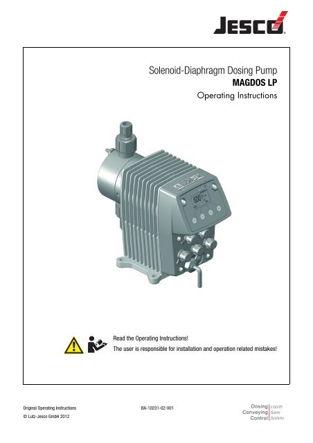
<strong>Solenoid</strong>-<strong>Diaphragm</strong> <strong>Dosing</strong> <strong>Pump</strong><br />
MAGDOS LP<br />
Operating Instructions<br />
Read the Operating Instructions!<br />
The user is responsible for installation and operation related mistakes!<br />
Original Operating Instructions<br />
© Lutz-Jesco GmbH 2012<br />
BA-10231-02-V01<br />
<strong>Dosing</strong><br />
Conveying<br />
Control<br />
Liquids<br />
Gases<br />
Systems
<strong>Solenoid</strong>-<strong>Diaphragm</strong> <strong>Dosing</strong> <strong>Pump</strong> MAGDOS LP<br />
Operating Instructions<br />
Contents<br />
1 Notes to the Reader .......................................................... 4<br />
General non-discrimination ........................................................... 4<br />
Explanations of signal words ......................................................... 4<br />
Explanations of warning signs ....................................................... 4<br />
Identification of warnings .............................................................. 4<br />
Identification of instructions for action ........................................... 4<br />
2 Safety ................................................................................ 5<br />
General warnings .......................................................................... 5<br />
Hazards due to non-compliance with the safety instructions.......... 6<br />
Safe operation ............................................................................... 6<br />
Personal protective equipment ...................................................... 6<br />
Personnel qualification .................................................................. 6<br />
3 Appropriate and intended use .......................................... 7<br />
Notes on product warranty ............................................................ 7<br />
Intended purpose .......................................................................... 7<br />
Device revision .............................................................................. 7<br />
Principles ...................................................................................... 7<br />
Prohibited dosing media ................................................................ 7<br />
Foreseeable misuse ...................................................................... 7<br />
4 Product Description .......................................................... 9<br />
Properties ..................................................................................... 9<br />
Scope of delivery ........................................................................... 9<br />
Structure of the dosing pump ........................................................ 9<br />
Function description .................................................................... 10<br />
Nameplate .................................................................................. 10<br />
5 Technical Data ................................................................ 11<br />
Delivery capacity data ................................................................. 11<br />
Operating conditions and limits ................................................... 11<br />
Electrical data ............................................................................. 12<br />
Other data ................................................................................... 12<br />
6 Dimensions...................................................................... 13<br />
MAGDOS LP with dosing head made of PVC, PP or PVDF ............. 13<br />
MAGDOS LP with dosing head made of stainless steel (1.4571)... 13<br />
7 Installing the <strong>Dosing</strong> <strong>Pump</strong> ............................................ 14<br />
Set up information ....................................................................... 14<br />
Installation examples ................................................................... 14<br />
8 Hydraulic installation ...................................................... 15<br />
Dimensioning of the system ........................................................ 15<br />
System piping ............................................................................. 16<br />
Aligning the dosing head ............................................................. 16<br />
Hydraulic connections ................................................................. 16<br />
Connecting a leakage drain ......................................................... 18<br />
Connecting the dosing head venting facility ................................. 18<br />
Hydraulic accessories.................................................................. 19<br />
Explanation of menu navigation................................................... 30<br />
Explanation of the menu icons .................................................... 30<br />
Menu settings at initial commissioning........................................ 31<br />
Main menu ................................................................................. 31<br />
System setup .............................................................................. 31<br />
Information about the dosing pump ............................................. 36<br />
Messages of the control unit ....................................................... 36<br />
11 Operation ........................................................................ 37<br />
Commissioning the dosing pump ................................................ 37<br />
Operating modes ........................................................................ 39<br />
External On/Off via Release input ................................................ 46<br />
Decommissioning the dosing pump............................................. 46<br />
Shutting down in an emergency .................................................. 46<br />
Storage ....................................................................................... 46<br />
Transportation ............................................................................ 46<br />
Disposal of old units .................................................................... 46<br />
12 Maintenance ................................................................... 47<br />
Maintenance intervals ................................................................. 47<br />
Tighten dosing head bolts ........................................................... 48<br />
Change the diaphragm ................................................................ 48<br />
Clean suction and discharge valves............................................. 48<br />
13 Troubleshooting .............................................................. 49<br />
Type of fault ................................................................................ 49<br />
List of control unit messages ...................................................... 51<br />
14 Spare parts ..................................................................... 52<br />
<strong>Diaphragm</strong> spare parts kits ......................................................... 52<br />
<strong>Dosing</strong> head spare parts kits including valves ............................. 52<br />
15 Delivery characteristic curves ....................................... 53<br />
16 Menu structure of the Control Unit ................................ 54<br />
Program start .............................................................................. 54<br />
System setup .............................................................................. 54<br />
Main menu ................................................................................. 57<br />
17 Appendix ......................................................................... 62<br />
Addresses of MODBUS TCP/IP protocol (MAGDOS LP-Net) ........... 62<br />
Default settings ........................................................................... 64<br />
18 EC Declaration of Conformity ......................................... 66<br />
19 Declaration of harmlessness ......................................... 67<br />
20 Warranty application ...................................................... 68<br />
21 Index ............................................................................... 69<br />
9 Electrical installation ...................................................... 26<br />
Principles .................................................................................... 26<br />
Description of connection sockets ............................................... 26<br />
10 Control ............................................................................. 30<br />
Operator controls of the control unit ............................................ 30<br />
© Lutz-Jesco GmbH 2012<br />
Subject to technical changes.<br />
BA-10231-02-V01<br />
3
<strong>Solenoid</strong>-<strong>Diaphragm</strong> <strong>Dosing</strong> <strong>Pump</strong> MAGDOS LP<br />
Operating Instructions<br />
1 Notes to the Reader<br />
These Operating instructions contain the information and rules of behaviour<br />
necessary for safe and correct operation of MAGDOS LP and<br />
MAGDOS LP-Net dosing pumps.<br />
1.3 Explanations of warning signs<br />
Warning signs represent the type and source of a danger:<br />
Follow these principles:<br />
• Read the entire Operating instructions prior to commissioning the<br />
unit.<br />
• Ensure that everyone who works with or on the dosing pump has<br />
read the operating instructions and follows them.<br />
• Keep the operating instructions for the entire service life of the<br />
dosing pump.<br />
• Pass on the operating instructions to any subsequent owner of the<br />
dosing pump.<br />
1.1 General non-discrimination<br />
In these operating instructions, only the male gender is used where<br />
grammar allows gender allocation. The purpose of this is to make the<br />
text easy to read. Men and women are always referred to equally. We<br />
would like to ask female readers for understanding of this text simplification.<br />
Warning sign<br />
Type of danger<br />
General danger zone<br />
Danger of electric shock<br />
Danger of caustic or other burns.<br />
Danger of explosions<br />
Danger of automatic start up<br />
1.2 Explanations of signal words<br />
Different signal words in combination with warning signs are used in<br />
these Operating instructions. Signal words illustrate the gravity of<br />
possible injuries if the risk is ignored:<br />
Table 1-2: Explanations of warning signs<br />
Danger of damage to machine or compromised<br />
function.<br />
A<br />
Signal word<br />
DANGER<br />
WARNING<br />
Meaning<br />
Refers to imminent danger. Ignoring this sign may<br />
lead to death or the most serious injuries.<br />
Refers to a potentially hazardous situation.<br />
Ignoring this sign might lead to death or the most<br />
serious injuries.<br />
1.4 Identification of warnings<br />
Warnings are intended to help you recognise risks and avoid negative<br />
consequences.<br />
This is how warnings are identified:<br />
Warning sign<br />
SIGNAL WORD<br />
CAUTION<br />
Note<br />
Refers to a potentially hazardous situation.<br />
Ignoring this sign may lead to light injuries or<br />
damage to property.<br />
Refers to a danger which, if ignored, may<br />
compromise the unit or its function.<br />
Description of danger.<br />
Consequences if ignored.<br />
The arrow signals a precautionary measure to be taken to eliminate<br />
the danger.<br />
Table 1-1: Explanations of signal words<br />
1.5 Identification of instructions for action<br />
This is how pre-conditions for action are identified:<br />
Pre-condition for action which must be met before taking action.<br />
This is how instructions for action are identified:<br />
Separate step with no follow-up action.<br />
1. First step in a series of steps.<br />
2. Second step in a series of steps.<br />
Result of the above action.<br />
Action completed, aim achieved.<br />
4<br />
Notes to the Reader<br />
General non-discrimination<br />
BA-10231-02-V01
<strong>Solenoid</strong>-<strong>Diaphragm</strong> <strong>Dosing</strong> <strong>Pump</strong> MAGDOS LP<br />
Operating Instructions<br />
2 Safety<br />
2.1 General warnings<br />
The following warnings are intended to help you to eliminate the<br />
dangers that can arise while handling the dosing pump. Risk prevention<br />
measures always apply regardless of any specific action.<br />
Safety instructions warning against risks arising from specific activities<br />
or situations can be found in the respective sub-chapters.<br />
DANGER<br />
Danger to life due to electric shock<br />
Wrongly connected or located cables or damaged ones can injure<br />
you.<br />
Connect the device only to a socket outlet with earthing contact<br />
protected by a ground fault circuit interrupter (GFCI).<br />
Replace damaged cables without delay.<br />
Do not use extension cables.<br />
Do not bury cables.<br />
Secure cables to avoid being damaged by other equipment.<br />
DANGER<br />
Danger to life through explosions!<br />
When using dosing pumps without ATEX certification in a potentially<br />
explosive area, explosions can occur that result in fatal injuries.<br />
Never use the MAGDOS LP dosing pump in potentially explosive<br />
areas.<br />
WARNING<br />
Caustic burns or other burns through dosing media!<br />
After connecting the mains supply, residual dosing media in the<br />
dosing head can spray out.<br />
Before connecting the mains supply, connect the dosing lines.<br />
Check that all the screw connections have been tightened correctly<br />
and are leak-proof.<br />
WARNING<br />
Caustic burns or other burns through dosing media!<br />
While working on the dosing head, valves and connections, you may<br />
come into contact with dosing media.<br />
Use sufficient personal protective equipment.<br />
Rinse the dosing pump with a liquid (e.g. water) which does not<br />
pose any risk. Ensure that the liquid is compatible with the<br />
dosing medium.<br />
Release pressure in hydraulic parts.<br />
Never look into open ends of plugged pipelines and valves.<br />
WARNING<br />
Caustic burns or other burns through dosing media!<br />
The materials of the dosing pump and hydraulic parts of the system<br />
must be suitable for the dosing medium that is used. Should this not<br />
be the case, the dosing media may leak.<br />
Make sure that the materials you are using are suitable for the<br />
dosing medium.<br />
Make sure that the lubricants, adhesives, sealants, etc. that you<br />
use are suitable for the dosing medium.<br />
CAUTION<br />
Increased risk of accidents due to insufficient qualification<br />
of personnel!<br />
<strong>Dosing</strong> pumps and their accessories may only be installed, operated<br />
and maintained by personnel with sufficient qualifications. Insufficient<br />
qualification will raise the risk of accidents.<br />
Ensure that all action is taken only by personnel with sufficient<br />
and corresponding qualifications.<br />
Prevent access to the system for unauthorised persons.<br />
CAUTION<br />
Danger of personal injury and material damage!<br />
Changing dosing media can lead to unpredictable reactions.<br />
Thoroughly clean the dosing pump and appropriate sections of<br />
the plant to avoid chemical reactions.<br />
© Lutz-Jesco GmbH 2012<br />
Subject to technical changes.<br />
BA-10231-02-V01<br />
Safety<br />
General warnings<br />
5
<strong>Solenoid</strong>-<strong>Diaphragm</strong> <strong>Dosing</strong> <strong>Pump</strong> MAGDOS LP<br />
Operating Instructions<br />
2.2 Hazards due to non-compliance with the safety<br />
instructions<br />
Failure to observe the safety instructions can pose a risk not only to the<br />
personnel, but consequentially to the environment and the unit.<br />
The specific consequences can be:<br />
• Failure of vital functions of the dosing pump and the system,<br />
• failure of required maintenance and repair methods,<br />
• danger for individuals through dangerous dosing media,<br />
• danger to the environment through substances leaking from the<br />
system.<br />
2.3 Safe operation<br />
Besides the safety instructions specified in these Operating instructions,<br />
further safety rules apply and must be followed:<br />
• Accident prevention regulations,<br />
• safety and operating provisions,<br />
• safety provisions for handling dangerous substances (mostly the<br />
safety data sheets to dosing media),<br />
• environmental protection provisions,<br />
• applicable standards and legislation.<br />
2.4 Personal protective equipment<br />
Based on the degree of risk posed by the dosing medium and the type<br />
of work you are carrying out, you must use corresponding protective<br />
equipment. Read the Accident Prevention Regulations and the Safety<br />
Data Sheets to the dosing media find out what protective equipment you<br />
need.<br />
As a minimum, the following protective equipment is recommended:<br />
Protective clothing Protective gloves Goggles<br />
Corresponding protective equipment must be used during these tasks:<br />
• Commissioning,<br />
• working on the dosing pump while running,<br />
• decommissioning,<br />
• maintenance work,<br />
• disposal.<br />
2.5 Personnel qualification<br />
• Knowledge of safety equipment and the way this equipment functions,<br />
• Knowledge of these Operating instructions, particularly of safety<br />
instructions and sections relevant for the job,<br />
• Knowledge of fundamental regulations regarding health and safety<br />
and accident prevention.<br />
All persons must generally have the following minimum qualification:<br />
• Training as specialists to carry out work on the dosing pump unsupervised,<br />
• Sufficient training that they can work on the dosing pumpunder the<br />
supervision and guidance of a trained specialist.<br />
These Operating instructions differentiate these user groups:<br />
2.5.1 Expert staff<br />
Expert staff are able, thanks to their professional training, knowledge<br />
and experience as well as knowledge of the respective provisions, to do<br />
the job allocated to them and recognise and/or eliminate any possible<br />
dangers by themselves.<br />
2.5.2 Trained person<br />
Trained persons have been trained by the user into the tasks they are<br />
supposed to perform and into the dangers stemming from improper<br />
behaviour.<br />
In the table below you can check what qualifications are the pre-condition<br />
for the respective tasks. Only people with appropriate qualifications<br />
are allowed to perform these tasks!<br />
Qualification<br />
Expert staff<br />
Trained person<br />
Table 2-1: Personnel qualification<br />
Tasks<br />
• Assembly<br />
• Hydraulic installations<br />
• Electrical installations<br />
• Maintenance<br />
• Repairs<br />
• Commissioning<br />
• Decommissioning<br />
• Disposal<br />
• Troubleshooting<br />
• Storage<br />
• Transportation<br />
• Control<br />
• Troubleshooting<br />
Any personnel who work on the dosing pump must have appropriate<br />
special knowledge and skills.<br />
Anybody who works with the dosing pump must meet the conditions<br />
below:<br />
• Attendance at all the training courses offered by the owner,<br />
• Personal suitability for the respective job,<br />
• Sufficient qualification for the respective job,<br />
• Training in handling of the dosing pump,<br />
6<br />
Safety<br />
Hazards due to non-compliance with the safety instructions<br />
BA-10231-02-V01
<strong>Solenoid</strong>-<strong>Diaphragm</strong> <strong>Dosing</strong> <strong>Pump</strong> MAGDOS LP<br />
Operating Instructions<br />
3 Appropriate and intended use<br />
3.1 Notes on product warranty<br />
Any non-designated use of the product can compromise its function or<br />
intended protection. This leads to invalidation of any warranty claims!<br />
Please note that liability is on the side of the user in the following cases:<br />
• The dosing pump is operated in a manner which is not consistent<br />
with these Operating instructions, particularly the safety and<br />
handling instructions and the chapter entitled "Appropriate and<br />
intended use".<br />
• If people operate the product who are not adequately qualified to<br />
carry out their respective activities,<br />
• No original spare parts or accessories of Lutz-Jesco GmbH are used,<br />
• Unauthorised changes are made to the device by the user,<br />
• The user uses different dosing media than those indicated in the<br />
order,<br />
• The user does not use dosing media under the conditions agreed<br />
with the manufacturer such as modified concentration, density,<br />
temperature, contamination, etc.<br />
3.2 Intended purpose<br />
The MAGDOS LP dosing pump is intended for the following purpose: the<br />
conveying and dosing of liquids.<br />
3.3 Device revision<br />
This operating manual applies to the following devices:<br />
Device<br />
3.4 Principles<br />
Month / year of<br />
manufacture<br />
MAGDOS LP 07/2012 onwards 1.25<br />
MAGDOS LP-Net 07/2012 onwards 1.25<br />
Table 3-1:<br />
Device revision<br />
Firmware<br />
• Before delivery, the manufacturer inspected the dosing pump and<br />
operated it under specific conditions (with a specific dosing medium<br />
with a specific density and temperature, with specific pipe dimensions,<br />
etc.) Since these conditions vary at every installation location,<br />
you must calibrate the dosing pump after delivery. For information<br />
on the calibration procedure refer to „Calibrating the dosing pump“<br />
(see page 38). For details on the approximate values and the<br />
capacity of the dosing pump, refer to the chapter entitled „Delivery<br />
characteristic curves“ (see page 53).<br />
• Information on the usage and environment (see „Technical Data“ on<br />
page 11) applies.<br />
• Any restrictions regarding the viscosity, temperature and density of<br />
dosing media must be followed. You must only use dosing media at<br />
temperatures above freezing point or below the boiling point of the<br />
respective medium.<br />
• The materials of the dosing pump and hydraulic parts of the system<br />
must be suitable for the dosing medium that is used. In this connection,<br />
note that the resistance of these components can change in<br />
dependence on the temperature of the media and the operating<br />
pressure.<br />
i<br />
Information on the suitability of materials combined with<br />
different dosing media can be found in the Chemical Resistance<br />
List of Lutz-Jesco GmbH.<br />
The information in this resistance list is based on information<br />
from the material manufacturers and on expertise obtained<br />
by Lutz-Jesco from handling the materials.<br />
As the durability of the materials depends on many factors,<br />
this list only constitutes initial guidance on selecting material.<br />
In all cases, test the equipment with the chemicals you use<br />
under operating conditions.<br />
• The dosing pump is not intended for outdoor use unless appropriate<br />
protective measures have been taken.<br />
• Avoid leaks of liquids and dust into the casing and avoid direct exposure<br />
to sunlight.<br />
• You must never operate dosing pumps in a potentially explosive<br />
atmosphere if they do not have corresponding nameplates or an<br />
appropriate EC Declaration of Conformity for potentially explosive<br />
atmospheres.<br />
3.5 Prohibited dosing media<br />
The dosing pump must not be used for these media and substances:<br />
• Gaseous media,<br />
• radioactive media,<br />
• solid substances,<br />
• combustible media,<br />
• all other media that are not suitable for delivery using this dosing<br />
pump.<br />
3.6 Foreseeable misuse<br />
Below, there is information about the applications of the dosing pump or<br />
associated equipment that are not considered to be intended use. This<br />
chapter is intended to allow you to detect possible misuse in advance<br />
and to avoid it.<br />
Foreseeable misuse is assigned to the individual stages of the product<br />
lifetime:<br />
3.6.1 Faulty assembly<br />
• Unstable or unsuitable bracket<br />
• <strong>Dosing</strong> pump bolted wrongly or loosely<br />
© Lutz-Jesco GmbH 2012<br />
Subject to technical changes.<br />
BA-10231-02-V01<br />
Appropriate and intended use<br />
Notes on product warranty<br />
7
<strong>Solenoid</strong>-<strong>Diaphragm</strong> <strong>Dosing</strong> <strong>Pump</strong> MAGDOS LP<br />
Operating Instructions<br />
3.6.2 Faulty hydraulic installation<br />
• Suction and pressure lines dimensioned incorrectly<br />
• Unsuitable connection of the pipes due to wrong material or unsuitable<br />
connections.<br />
• Suction and pressure lines mixed-up<br />
• Damage to threads due to them being tightened too much<br />
• Bending of pipelines<br />
• No free return flow of the pressure relief valve<br />
• Excessive demand due to the pressure differences between the<br />
suction and discharge valves<br />
• Through-suction at installation without pressure control valves<br />
• Damage due to undamped acceleration mass forces<br />
• Exceeding the admissible pressure on the suction and discharge<br />
sides<br />
• Using damaged parts<br />
3.6.3 Faulty electrical installation<br />
• Connecting the mains voltage without a protective earth<br />
• Unsecured mains or one that does not conform to standards<br />
• Not possible to immediately or easily disconnect the power supply<br />
• Wrong connecing cables for mains voltage<br />
• <strong>Dosing</strong> pump accessories connected to wrong sockets<br />
• <strong>Diaphragm</strong> monitoring not connected or defective<br />
• Protective earth removed<br />
3.6.4 Faulty commissioning<br />
• Commissioning with damaged plant<br />
• Shut-off valves closed at commissioning<br />
• Closed suction or pressure line, e.g. due to blockages<br />
• Personnel was not informed before commissioning<br />
• System was recommissioned after maintenance without all the<br />
protective equipment and fixtures, etc. being reconnected.<br />
• Inadequate protective clothing or none at all<br />
3.6.5 Faulty operation<br />
• Protective equipment not functioning correctly or dismantled<br />
• Modification of the dosing pump without authority<br />
• Ignoring operational disturbances<br />
• Elimination of operational disturbances by personnel without<br />
adequate qualifications<br />
• Deposits in the dosing head due to inadequate purging, particularly<br />
with suspensions<br />
• Bridging the external fuse<br />
• Operation made more difficult due to inadequate lighting or<br />
machines that are difficult to access<br />
• Operation not possible due to dirty or illegible display of the dosing<br />
pump<br />
• Delivery of dosing media for which the system is not designed<br />
• Delivery of particulate or contaminated dosing media<br />
• Inadequate protective clothing or none at all<br />
• Carrying out maintenance during ongoing operation<br />
• Carrying out work that is not described in the operating instructions<br />
• No adequate or regular inspection of correct functioning<br />
• No replacement of damaged parts or cables with inadequate insulation<br />
• No securing against reactivation during maintenance work<br />
• Using cleaning materials that can cause reactions with the dosing<br />
media<br />
• Inadequate cleaning of the system<br />
• Unsuitable purging medium<br />
• Unsuitable cleaning materials<br />
• Cleaning materials left in system sections<br />
• Using unsuitable cleaning equipment<br />
• Using the wrong spares or lubricants<br />
• Contaminating the dosing medium with lubricant<br />
• Installing spares without following the instructions in the operating<br />
manual<br />
• Blocking venting orifices<br />
• Pulling off sections of the plant<br />
• Contamination at installation without a dirt trap<br />
• Mixing up the valves<br />
• Mixing up the sensor lines<br />
• Not reconnecting all the lines<br />
• Damaging or not installing all the seals<br />
• Not renewing seals<br />
• Not paying attention to safety data sheets<br />
• Inadequate protective clothing or none at all<br />
3.6.7 Faulty decommissioning<br />
• Not completely removing the dosing medium<br />
• Dismantling lines while the dosing pump is running<br />
• Device not disconnected from the power supply<br />
• Using the wrong dismantling tools<br />
• Inadequate protective clothing or none at all<br />
3.6.8 Faulty disposal<br />
• Incorrect disposal of dosing media, operating resources and other<br />
materials<br />
• No labelling of hazardous substances<br />
3.6.6 Faulty maintenance<br />
8<br />
Appropriate and intended use<br />
Foreseeable misuse<br />
BA-10231-02-V01
<strong>Solenoid</strong>-<strong>Diaphragm</strong> <strong>Dosing</strong> <strong>Pump</strong> MAGDOS LP<br />
Operating Instructions<br />
4 Product Description<br />
4.1 Properties<br />
The MAGDOS LP is a <strong>Solenoid</strong>-<strong>Diaphragm</strong> <strong>Dosing</strong> <strong>Pump</strong> that is used<br />
when precise dosing results are required.<br />
They are characterized by the following properties:<br />
• Output range from 0.5 to 15 l/h, up to 16 bar,<br />
• Reproducible dosing precision of 2%,<br />
• Integrated automatic dosing head venting facility (except with stainless<br />
steel dosing heads),<br />
• Suitable for highly aggressive or poisonous dosing media,<br />
• Operating modes: Manual mode, analog input, pulse input, batch<br />
mode and network mode (MAGDOS LP-Net only),<br />
• Graphic display: 128 x 64 px, 1.5“, monochrome, illuminated,<br />
• Menu languages: English, German, French, Spanish, Portuguese,<br />
Dutch,<br />
• Four multifunction keys for operator inputs,<br />
• Real-time clock and date,<br />
• Floor- and wall-mounting options,<br />
• Release code and security code,<br />
• Calibration option,<br />
• 2 Eco-Mode energy-saving modes,<br />
• Connections: M12x1 connector, A-, B- or D-coded,<br />
• Ethernet, network connection (MAGDOS LP-Net only).<br />
4.3 Structure of the dosing pump<br />
4.3.1 General Overview<br />
<br />
<br />
Fig. 4-1: Overview of MAGDOS LP dosing pump<br />
No.<br />
Description<br />
<strong>Dosing</strong> head<br />
Drive unit<br />
<br />
4.2 Scope of delivery<br />
<br />
Control unit<br />
Please compare the delivery note with the scope of delivery. The<br />
following items are part of the scope of delivery:<br />
• MAGDOS LP dosing pump,<br />
• One set each of hose clamping connections for the suction and<br />
discharge sides for hoses with diameters of 4/6 mm, 6/9 mm and<br />
6/12 mm (made of PVC, PP and PVDF),<br />
• 5 (MAGDOS LP) or 6 (MAGDOS LP-Net) covering caps for electrical<br />
connections (mounted on the dosing pump),<br />
• Mains cable,<br />
• Operating Manual,<br />
• Inspection report and test certificate (optional),<br />
• Accessory kit (optional).<br />
Table 4-1: Designation of components<br />
4.3.2 <strong>Dosing</strong> head<br />
<br />
<br />
<br />
<br />
Fig. 4-2: <strong>Dosing</strong> head<br />
No.<br />
<br />
<br />
Description<br />
Valve and connection on the discharge side<br />
integrated dosing head venting facility (plastic version only)<br />
Table 4-2: Designation of components<br />
© Lutz-Jesco GmbH 2012<br />
Subject to technical changes.<br />
BA-10231-02-V01<br />
Product Description<br />
Properties<br />
9
<strong>Solenoid</strong>-<strong>Diaphragm</strong> <strong>Dosing</strong> <strong>Pump</strong> MAGDOS LP<br />
Operating Instructions<br />
No.<br />
<br />
<br />
Arrow indicating the direction of throughflow of the dosing<br />
medium<br />
Valve and connection on the suction side<br />
Table 4-2: Designation of components<br />
4.3.3 Control elements<br />
<br />
Description<br />
<br />
4.5 Nameplate<br />
There is information on the equipment about safety or the product's way<br />
of functioning. The information must stay legible for the duration of the<br />
service life of the product.<br />
<br />
<br />
<br />
<br />
<br />
Lutz-Jesco GmbH<br />
30900 Wedemark Germany<br />
MAGDOS LP<br />
*12345678012345* XX/XXXX<br />
P/N:<br />
S/N: XXXXXXXXXX<br />
*102A12345678*<br />
Material:<br />
Made in Germany<br />
Max. XXX l/h at bar<br />
Max. XXX l/h at bar<br />
IP XX, XXX V, XXXX Hz, XX W<br />
<br />
<br />
<br />
<br />
<br />
<br />
Fig. 4-4: MAGDOS LP nameplate<br />
<br />
Fig. 4-3: Controller of MAGDOS LP dosing pump<br />
No.<br />
<br />
<br />
<br />
<br />
Graphic display<br />
Description<br />
Multifunction keys on the contol unit for operator inputs<br />
Connection sockets for external operation or connecting accessories<br />
Mains cable for power supply<br />
Table 4-3: Designation of components<br />
No.<br />
<br />
<br />
<br />
<br />
<br />
<br />
<br />
<br />
<br />
<br />
Description<br />
Product, type, nominal size<br />
Part number<br />
Type of material of dosing head/ type of material of seals<br />
Maximum delivery capacity at average pressure<br />
Maximum delivery capacity at maximum pressure<br />
Protection class<br />
Voltage supply<br />
Frequency<br />
Power consumption<br />
WEEE label<br />
4.4 Function description<br />
<strong>Dosing</strong> pumps are positive displacement pumps. They are used if<br />
precisely defined delivery of a medium is necessary. A constant volume<br />
per stroke or time is delivered.<br />
The system delivers or meters the dosing medium by means of a<br />
repeated sequence of suction strokes followed by pressure strokes. This<br />
results in a pulsing flow.<br />
If the dosing pump is in the suction stroke phase, the diaphragm is<br />
pulled into the rear final position. Due to the resulting vacuum in the<br />
dosing head, the discharge valve closes, the suction valve opens and<br />
dosing medium flows from the suction line into the dosing head.<br />
If the dosing pump is in the pressure stroke phase, the diaphragm is<br />
moved into the front final position. Due to the pressure in the dosing<br />
head, the suction valve closes and the dosing medium flows through the<br />
discharge valve from the dosing head into the pressurised pipe.<br />
Label showing conformity with applicable European directives<br />
Month / year of manufacture<br />
Serial number<br />
Table 4-4: Nameplate<br />
10<br />
Product Description<br />
Function description<br />
BA-10231-02-V01
<strong>Solenoid</strong>-<strong>Diaphragm</strong> <strong>Dosing</strong> <strong>Pump</strong> MAGDOS LP<br />
Operating Instructions<br />
5 Technical Data<br />
5.1 Delivery capacity data<br />
Please note that some of this data only represents guide values. The actual capacity of a dosing pump depends on various factors. For approximate<br />
values of the delivery capacity at diffferent pressures, refer to „Delivery characteristic curves“ (see page 53).<br />
Information<br />
Value<br />
MAGDOS LP size<br />
05 1 2 4 6 10 15<br />
Delivery capacity at max. backpressure<br />
l/h 0.36 0.76 1.9 3.4 6.2 9.0 13<br />
ml/stroke 0.05 0.05 0.2 0.31 0.57 0.83 0.86<br />
max. back pressure bar 16 8 6 3<br />
Max. delivery pressure in Eco-Mode 1* bar 10 6 4 2<br />
Max. delivery pressure in Eco-Mode 2* bar 6 4 2 1<br />
Delivery capacity at average backpressure<br />
l/h 0.54 1.1 2.3 3.8 6.8 10 15<br />
ml/stroke 0.08 0.07 0.24 0.35 0.63 0.92 1.0<br />
Average back pressure bar 8 4 3 1<br />
Max. stroke frequency RPM 120 250 160 180 250<br />
Suction head for non-gassing media<br />
(suction line filled)<br />
mWS 5 3 2<br />
Table 5-1: Output data<br />
* In the case of operation in Eco-Mode energy saving mode, the delivery capacity is 5-10 % less than in normal mode (with the same backpressure).<br />
If necessary, recalibration may be necessary (see „Calibrating the dosing pump“ on page 38).<br />
5.2 Operating conditions and limits<br />
Information<br />
Value<br />
MAGDOS LP size<br />
05 – 15<br />
Max. ambient temperature °C 45 (40 with PVC parts)<br />
Relative humidity % Max. 90<br />
Max. sound pressure level (depressurised) dB(A) 68 – 75<br />
Max. sound pressure level (at test pressure)<br />
dB(A) 65 – 70<br />
Max. supply pressure mbar 800<br />
Viscosity limits mPa s 300* / 1000**<br />
Linear dosing range % 10 – 100<br />
Table 5-2: Operating conditions and limits<br />
* With a viscosity of ~300 mPa s and above, you must use spring-loaded valves.<br />
** If the viscosity is above 1000 mPa s, this must be checked individually and the stroke frequency must be between 50 and 100 strokes/min.<br />
© Lutz-Jesco GmbH 2012<br />
Subject to technical changes.<br />
BA-10231-02-V01<br />
Technical Data<br />
Delivery capacity data<br />
11
<strong>Solenoid</strong>-<strong>Diaphragm</strong> <strong>Dosing</strong> <strong>Pump</strong> MAGDOS LP<br />
Operating Instructions<br />
5.2.1 Maximum temperature of the medium<br />
Information Value MAGDOS LP (all sizes)<br />
<strong>Dosing</strong> head made of PVC °C 0 – 35<br />
<strong>Dosing</strong> head made of PP °C 0 – 60<br />
<strong>Dosing</strong> head made of PVDF °C 0 – 80<br />
<strong>Dosing</strong> head made of stainless steel 1.4571 °C 0 – 80<br />
Table 5-3:<br />
Maximum temperature of the medium<br />
5.3 Electrical data<br />
Voltage supply<br />
Information<br />
Value<br />
MAGDOS LP size<br />
05 1 2 4 6 10 15<br />
110 - 240 V AC, -10% / +5%. 50/60 Hz<br />
Power consumption W 10 15 21 27 28 29 26<br />
Max. current consumption during dosing stroke A 2.0 3.0 3.7 3.8 4.1 3.6<br />
Eco-Mode 1<br />
Power consumption W 8 11 17 18 20 22 19<br />
Max. current consumption during dosing stroke A 1.7 2.5 2.9 3.1 3.6 2.9<br />
Eco-Mode 2<br />
Power consumption W 7 10 13 14 17 16 15<br />
Max. current consumption during dosing stroke A 1.5 2 2.2 2.7 2.4<br />
Table 5-4: Electric data<br />
5.4 Other data<br />
Information<br />
Value<br />
MAGDOS LP size<br />
05 1 2 4 6 10 15<br />
Weight (with dosing head made of PVC, PP or<br />
PVDF)<br />
Weight (with dosing head made of stainless<br />
steel)<br />
kg ~ 3.2<br />
kg ~ 4.3<br />
Diameter of diaphragm mm 24 33 39<br />
Electrical cable m 1.8 m (with mains plug)<br />
Protection class<br />
Insulation class<br />
Valve connection<br />
IP 65 (with covering caps on the connections)<br />
F<br />
G 5/8 external<br />
Valve size DN3 DN4<br />
Table 5-5: Other data<br />
12<br />
Technical Data<br />
Electrical data<br />
BA-10231-02-V01
<strong>Solenoid</strong>-<strong>Diaphragm</strong> <strong>Dosing</strong> <strong>Pump</strong> MAGDOS LP<br />
Operating Instructions<br />
6 Dimensions<br />
6.1 MAGDOS LP with dosing head made of PVC, PP or PVDF<br />
~ 225<br />
~ 171<br />
~ 180<br />
~ 59<br />
L<br />
~ 120 L<br />
Ø 80<br />
100<br />
116<br />
Ø 6,5<br />
~ 43<br />
~ 76<br />
70<br />
Fig. 6-1: Dimensioned drawing of MAGDOS LP with dosing head made of PVC, PP or PVDF (all dimensions in mm)<br />
Connection Material Size Nominal diameter L<br />
4/6 mm DN4 31<br />
Hose clip<br />
PVC / PP / PVDF<br />
1/4x3/8” 1/4“ 34<br />
6/9 mm DN6 34<br />
6/12 mm DN6 15<br />
6.2 MAGDOS LP with dosing head made of stainless steel (1.4571)<br />
~ 168<br />
~ 204<br />
~ 178<br />
~ 56<br />
L ~ 120<br />
L<br />
Ø 80<br />
Ø 6,5<br />
100<br />
116<br />
70<br />
~ 17<br />
~ 80<br />
Fig. 6-2: Dimensioned drawing of MAGDOS LP with dosing head made of stainless steel 1.4571 (all dimensions in mm)<br />
Connection Material Size Nominal diameter L<br />
Hose clip Stainless steel (1.4571) / PVDF 4/6 mm DN4 50<br />
Hose clip Stainless steel (1.4571) / PVDF 6/9 mm DN6 54<br />
© Lutz-Jesco GmbH 2012<br />
Subject to technical changes.<br />
BA-10231-02-V01<br />
Dimensions<br />
MAGDOS LP with dosing head made of PVC, PP or PVDF<br />
13
<strong>Solenoid</strong>-<strong>Diaphragm</strong> <strong>Dosing</strong> <strong>Pump</strong> MAGDOS LP<br />
Operating Instructions<br />
7 Installing the <strong>Dosing</strong> <strong>Pump</strong><br />
DANGER<br />
Danger to life due to electric shock!<br />
Electrically conductive liquid can enter pump housings, cable screw<br />
connections and mains connectors.<br />
Make sure that all protective measures comply at least with the<br />
requirements of protection class IP 65.<br />
Always set up the dosing pump such that water cannot enter the<br />
housing.<br />
7.2 Installation examples<br />
7.2.1 Installation on a wall bracket<br />
CAUTION<br />
Danger of personal injury and material damage!<br />
A dosing pump that is difficult to access represents a danger due to<br />
incorrect operation and faulty maintenance.<br />
Install the dosing pump such that it is accessible at all times.<br />
7.1 Set up information<br />
When installing, follow the basic principles below:<br />
• The valves must be vertical: Discharge valve at top, suction valve at<br />
bottom. in this connection, pay attention to the arrow on the dosing<br />
head. The dosing head must be aligned such that the arrow points<br />
vertically upwards.<br />
• You should install the dosing pump at a convenient height for operation.<br />
• It must not be installed under the ceiling.<br />
• The frame of foundation for fixing the dosing pump must not be<br />
subjected to jolts. The pump must be vibration-free and stable.<br />
• There must be enough free space in the area of the dosing head and<br />
the suction and discharge valves for these parts to be easily dismantled<br />
if required. The entire space requirement for installation and<br />
maintenance is approximately 1 m².<br />
• The distance from the sides of the dosing pump to the wall or other<br />
dosing pumps or equipment must be at least 3 cm. There must be a<br />
guaranteed flow of circulating air.<br />
• The maximum ambient temperature must be complied with, see<br />
“Operating conditions and limits” on page 11. If necessary, radiated<br />
heat from surrounding equipment must be screened.<br />
• Avoid exposure to direct sunlight.<br />
• The dosing pump is not intended for use out of doors unless appropriate<br />
protective measures have been taken to prevent dust and<br />
water from entering the housing.<br />
• For the dimensions of the fastening holes, refer to „Dimensions“<br />
(see page 13).<br />
• The tightening torque for the fastening bolts is 1.5 - 2 Nm.<br />
Fig. 7-1: Installation on a wall bracket<br />
To reduce the structure-borne noise, the dosing pump is bolted to the<br />
wall bracket using rubber elements. The materials necessary for this are<br />
included with the wall bracket.<br />
7.2.2 Installation on the wall<br />
Fig. 7-2: Installation on the wall<br />
The dosing pump can be mounted to the floor or directly to the wall<br />
without the need for additional elements. Turn the dosing head appropriately<br />
to ensure the flow direction of the medium through the dosing<br />
head.<br />
14<br />
Installing the <strong>Dosing</strong> <strong>Pump</strong><br />
Set up information<br />
BA-10231-02-V01
<strong>Solenoid</strong>-<strong>Diaphragm</strong> <strong>Dosing</strong> <strong>Pump</strong> MAGDOS LP<br />
Operating Instructions<br />
8 Hydraulic installation<br />
In this chapter, you will find information about the hydraulic parts of a<br />
system that you should install or that can install additionally. In many<br />
cases, you must install hydraulic accessories to be able to use all the<br />
functions that the dosing pump MAGDOS LP offers, to guarantee functional<br />
safety or to achieve a high level of dosing precision.<br />
WARNING<br />
Caustic burns or other burns through dosing media!<br />
The materials of the dosing pump and hydraulic parts of the system<br />
must be suitable for the dosing medium that is used. Should this not<br />
be the case, the dosing media may leak. Depending on the type and<br />
hazardousness of the dosing medium, this can result in injury.<br />
Make sure that the materials you are using are suitable for the<br />
dosing medium.<br />
Make sure that the lubricants, adhesives, sealants, etc. that you<br />
use are suitable for the dosing medium.<br />
WARNING<br />
Caustic burns or other burns through dosing media!<br />
If there is a diaphragm rupture, the dosing medium can escape in<br />
an uncontrolled way. Depending on the type and hazardousness of<br />
the dosing medium, this can result in injury.<br />
Install a leakage drain.<br />
WARNING<br />
Caustic burns or other burns through dosing media!<br />
The dosing pump can generate a pressure that is many times the<br />
rated one. A blocked pressure line can lead to dosing medium<br />
escaping. Depending on the type and hazardousness of the dosing<br />
medium, this can result in injury.<br />
Install pressure relief valves.<br />
CAUTION<br />
Danger of personal injury and material damage!<br />
High peak pressures can lead to piping vibrating and cause them to<br />
snap. This can result in injury due to uncontrollable piping or escaping<br />
dosing media.<br />
Install pulsation dampeners.<br />
8.1 Dimensioning of the system<br />
NOTICE<br />
Damage to drives due to overloading<br />
The pressure conditions between the suction and discharge sides<br />
must be balanced; otherwise, overloading can result. This can lead<br />
to uncontrolled dosing processes, damage to the plant pipework<br />
and to the dosing pump.<br />
Ensure that the pressure on the discharge side is at least 1 bar<br />
than on the suction side.<br />
NOTICE<br />
Locking of threads<br />
Stainless steel and plastic parts (particularly those made of PVC)<br />
that are bolted together in a detachable connection (e.g. the dosing<br />
head and the valves) can lock. This makes them difficult to release.<br />
Before bolting, grease the corresponding parts with a lubricant,<br />
e.g. PTFE spray).<br />
Ensure that the lubricant is compatible with the dosing medium.<br />
• The dosing pump’s technical data (see „Technical Data“ on page 11)<br />
must be taken into account and the plant’s layout must be set up<br />
appropriately (e.g. pressure loss when rating the lines with regard to<br />
their nominal diameter and length).<br />
• You must design the entire plant and its integrated dosing pump<br />
such that escaping dosing medium due to the failure of wearing<br />
parts such as the diaphragm, or to burst hoses does not lead to<br />
permanent damage to parts of the system or the premises.<br />
• The leakage opening of the dosing head must be visible so that you<br />
can detect a diaphragm failure. It must be possible for the outflow<br />
from the leakage drain to be on a free downwards gradient.<br />
• If you use hazardous dosing media, the installation must be designed<br />
such that no disproportionately high consequential damages arise<br />
due to dosing media escaping.<br />
• To avoid dosing errors after the end of the process, the dosing pump<br />
must be locked hydraulically.<br />
• To allow you to easily inspect the pressure conditions in the system,<br />
you should provide connections for pressure gauges close to the<br />
suction and discharge valves.<br />
© Lutz-Jesco GmbH 2012<br />
Subject to technical changes.<br />
BA-10231-02-V01<br />
Hydraulic installation<br />
Dimensioning of the system 15
<strong>Solenoid</strong>-<strong>Diaphragm</strong> <strong>Dosing</strong> <strong>Pump</strong> MAGDOS LP<br />
Operating Instructions<br />
8.2 System piping<br />
• The system piping must not exert any force on the connections and<br />
valves of the dosing pump.<br />
• This means that steel piping should be connected to the dosing<br />
pump by means of flexible pipe sections.<br />
• The nominal diameters of the pipework and the installed fittings<br />
should be rated the same as or greater than the nominal diameters<br />
of the dosing pump's suction and discharge valves.<br />
• The suction line should be kept as short as possible.<br />
• You should avoid intertwined hoses.<br />
• Avoid loops, since air bubbles can collect.<br />
8.3 Aligning the dosing head<br />
<br />
8.4 Hydraulic connections<br />
8.4.1 Connecting hose clips<br />
Choose the hose connection according to the condition of the hose<br />
(material, inner diameter, wall thickness) in order to ensure maximum<br />
pressure resistance.<br />
8.4.1.1 Sizes 4/6 and 6/9<br />
4/6 6/9<br />
<br />
<br />
<br />
<br />
<br />
<br />
<br />
<br />
<br />
<br />
<br />
Fig. 8-2: Hose clips 4/6 and 6/9 (internal and external diameters in mm)<br />
Fig. 8-1: Aligning the dosing head<br />
When connecting the dosing lines to the dosing pump, you must<br />
observe the direction of through-flow (see arrow ).The dosing head<br />
must be aligned vertically.<br />
The suction valve must always point downwards. Accordingly, arrow<br />
and pressure valve always point upwards. This is irrespective of<br />
the positioning of the dosing head to the drive.<br />
<br />
Perform the following working steps:<br />
1. Cut the hose to length neatly and at an exact right angle.<br />
2. Place a gasket that is suitable for the dosing medium between the<br />
connection and the valve.<br />
3. Screw the connecting piece to the dosing pump's valve using<br />
the .<br />
4. Thread the union nut and the clamping ring onto the hose.<br />
5. Plug the hose all the way in to the grommet of connection piece<br />
.<br />
6. Push the clamping ring onto the grommet of connection piece<br />
and screw it to the union nut .<br />
7. Carry out the same procedure with the connection to the dosing<br />
pump's other valve.<br />
Hose clip connected.<br />
16<br />
Hydraulic installation<br />
System piping<br />
BA-10231-02-V01
<strong>Solenoid</strong>-<strong>Diaphragm</strong> <strong>Dosing</strong> <strong>Pump</strong> MAGDOS LP<br />
Operating Instructions<br />
8.4.1.2 Size 6/12<br />
<br />
8.4.2 Making the bonded connection<br />
<br />
<br />
<br />
<br />
<br />
Fig. 8-3: Hose clip 6/12 (internal and external diameter in mm)<br />
Size 6/12 hose clips only have a union nut. It clamps the hose onto the<br />
grommet of the connection piece and at the same time fastens on the<br />
dosing pump's valve.<br />
Perform the following working steps:<br />
1. Cut the hose to length neatly and at an exact right angle.<br />
2. Place a gasket that is suitable for the dosing medium between the<br />
connection and the valve.<br />
3. Push the union nut and the cutting ring over the hose .<br />
4. Press the end of the hose onto the grommet of connection piece<br />
. You can do this more easily by moistening the end of the hose<br />
on the inside or applying some lubricant to the grommet in the cone<br />
area. You should push at least two thirds of the hose onto the<br />
grommet of the connection piece.<br />
5. Push the cutting ring over the hose into the cone area on the<br />
grommet of connection piece .<br />
6. Screw the union nut onto the valve of the dosing pump.<br />
Fig. 8-4: Bonded connection<br />
Perform the following working steps:<br />
1. Cut the PVC tube to length.<br />
2. Push the union nut onto the tube.<br />
3. Stick the bonded coupling sleeve to the tube (follow the instructions<br />
of the adhesive manufacturer).<br />
4. Screw the union nut onto the valve of the dosing pump. Use a<br />
gasket that is suitable for the dosing medium.<br />
Bonded connection made.<br />
8.4.3 Making the cemented connection<br />
<br />
<br />
Hose clip connected.<br />
Fig. 8-5: Cemented conn.<br />
Perform the following working steps:<br />
1. Cut the tube to length.<br />
2. Cut the thread onto the end of the tube.<br />
3. Push the union nut onto the tube.<br />
4. Seal the thread . When choosing your sealing material, take into<br />
account its resistance to material, temperature and pressure.<br />
5. Screw the union nut onto the valve of the dosing pump. Use a<br />
gasket that is suitable for the dosing medium.<br />
Cemented connection made.<br />
i<br />
Under normal conditions, you only need to screw the<br />
hydraulic connections finger-tight. However, due to the material<br />
settling, the pre-tension of the screw connection can<br />
slacken. This means that you must re-tighten the screw<br />
connection before carrying out commissioning.<br />
© Lutz-Jesco GmbH 2012<br />
Subject to technical changes.<br />
BA-10231-02-V01<br />
Hydraulic installation<br />
Hydraulic connections<br />
17
<strong>Solenoid</strong>-<strong>Diaphragm</strong> <strong>Dosing</strong> <strong>Pump</strong> MAGDOS LP<br />
Operating Instructions<br />
8.5 Connecting a leakage drain<br />
Lutz-Jesco GmbH dosing pumps are produced to the highest quality<br />
standards and have a long service life. However, some parts are subject<br />
to operational wear. This is the case particularly with the diaphragms<br />
that are continuously subjected to forces during the suction and<br />
discharge strokes and to the effects of the dosing medium.<br />
8.6 Connecting the dosing head venting facility<br />
The MAGDOS LP dosing heads have an integrated dosing head venting<br />
facility (except for dosing heads made of stainless steel).<br />
For the procedure when venting, refer to “Venting the dosing pump” on<br />
page 38.<br />
If a diaphragm ruptures, the dosing medium starts to leak. This leakage<br />
is drained via the leakage opening. On the flange of the dosing head,<br />
there are three openings for this purpose. Depending on the alignment<br />
of the dosing pump, the leakage is drained via the downward opening.<br />
It is advisable to use a diaphragm rupture sensor (see „<strong>Diaphragm</strong><br />
rupture sensor leak sensor“ on page 19).<br />
Fig. 8-7: <strong>Dosing</strong> head venting facility with hose connection<br />
Perform the following working steps:<br />
1. Connect a 4/6 hose to the dosing head venting facility.<br />
2. Route the other end of the hose into the dosing tank or a collecting<br />
tank.<br />
<strong>Dosing</strong> head venting facility connected.<br />
Fig. 8-6: Openings of the leakage drain<br />
NOTICE<br />
Damage to drives due to effervescent media<br />
If a hose is connected to the leakage drain and it is routed back into<br />
the dosing tank, effervescent media can enter the drive and<br />
damage it.<br />
Collect the leakage in a collecting pan.<br />
As an alternative, you can route the leakage back to to the<br />
dosing tank using a funnel. You should install the funnel at an<br />
adequate distance from the leakage opening.<br />
18<br />
Hydraulic installation<br />
Connecting a leakage drain<br />
BA-10231-02-V01
<strong>Solenoid</strong>-<strong>Diaphragm</strong> <strong>Dosing</strong> <strong>Pump</strong> MAGDOS LP<br />
Operating Instructions<br />
8.7 Hydraulic accessories<br />
The following chapter is intended to give you an overview of installation<br />
options.<br />
Please note that these operating instructions are no substitute for the<br />
instructions supplied with the accessories in each case. The corresponding<br />
documentation supplied with the product applies to safety<br />
information and provides exact instructions on assembly.<br />
8.7.1 Injection nozzle<br />
If the pressure line enters a main line, it is advisable to install an injection<br />
nozzle.<br />
Injection nozzles have three main functions:<br />
• <strong>Dosing</strong> the medium into a main line,<br />
• Preventing flowback into the pressure line through a non-return<br />
valve.<br />
Notes on assembly:<br />
• Double-ball injection nozzles must be installed into the main line<br />
vertically from the bottom. You can install hose and spring-loaded<br />
injection nozzles any way you like.<br />
• With dosing media that tend to crystallize, it is advisable to carry out<br />
installation into the main line from the bottom. This prevents air<br />
bubbles from being trapped.<br />
• Many dosing media tend to contaminate the injection nozzles, which<br />
can lead to blockages. In cases like this, it is advisable to install an<br />
injection nozzle that is easy to dismantle and block off.<br />
<br />
<br />
No.<br />
<br />
<br />
<br />
<br />
<br />
<br />
<br />
<br />
<br />
Table 8-1:<br />
Main line<br />
Description<br />
Injection nozzle with shut-off valve<br />
Pressure relief valve<br />
Chemical tank<br />
Pressure line<br />
MAGDOS LP dosing pump<br />
Wall bracket<br />
Shutoff valve<br />
Suction line<br />
Designation of components<br />
8.7.2 <strong>Diaphragm</strong> rupture sensor leak sensor<br />
If a diaphragm ruptures, the dosing medium starts to leak. The leakage<br />
is drained via the leakage opening.<br />
As an option, the MAGDOS LP dosing pump is supplied with a leak<br />
sensor in the diaphragm flange; in the case of a diaphragm rupture, the<br />
sensor passes on a signal to the dosing pump and stops it. The system<br />
shows a "<strong>Diaphragm</strong> rupture" message on the display and reports a<br />
disturbance. The dosing pump cannot restart until you press Start.<br />
You must first replace the diaphragm and clean dosing medium residue<br />
from the diaphragm flange. There must be no conducting connection<br />
between the two rings of the leak sensor.<br />
The connecting cable of the leak sensor has an M12x1 male connector<br />
that you connect to connection socket 5 (see „Connection socket 5“ on<br />
page 28).<br />
<br />
<br />
For an explanation of the icons, see “Set "<strong>Diaphragm</strong> rupture" menu<br />
item” on page 33.<br />
<br />
<br />
<br />
<br />
<br />
Fig. 8-8: Installation with an injection nozzle<br />
Fig. 8-9: MAGDOS LP with leak sensor in the diaphragm flange<br />
© Lutz-Jesco GmbH 2012<br />
Subject to technical changes.<br />
BA-10231-02-V01<br />
Hydraulic installation<br />
Hydraulic accessories<br />
19
<strong>Solenoid</strong>-<strong>Diaphragm</strong> <strong>Dosing</strong> <strong>Pump</strong> MAGDOS LP<br />
Operating Instructions<br />
8.7.3 Contact Water Meter<br />
The Contact Water Meter measures the throughflow in a pipe and sends<br />
a pulse to the dosing pump, which then starts dosing. This means that<br />
ideal proportional dosing is also possible with large throughflow fluctuations.<br />
The connecting cable of the Contact Water Meter has an M12x1 male<br />
connector that you connect to connection socket 2 (see „Connection<br />
socket 2“ on page 27).<br />
You determine the ratio of throughflow and executed strokes of the<br />
dosing pump in "Pulse input" mode, (see „Water meter“ on page 42).<br />
8.7.4 Pressure relief valve<br />
Pressure relief valves have an important safety function for protecting<br />
the dosing pump and the associated pipes and fittings.s The dosing<br />
pump can generate a pressure that is many times the rated one. A<br />
blocked pressure line can lead to dosing medium escaping.<br />
An inadmissibly high pressure can occur if:<br />
• the shut-off valves are closed even though the dosing pump is<br />
running,<br />
• pipes block.<br />
At an appropriate pressure, a pressure relief valve opens a bypass line<br />
and protects the system in this way from pressures that are too high.<br />
Notes on assembly:<br />
• The line for returning dosing medium from the pressure relief valve<br />
must be routed to the dosing tank or to a collecting pan.<br />
• The pressure in the dosing tank must not be too high so that it is<br />
possible to accommodate the returned dosing medium.<br />
• As an alternative, the system can return dosing medium into the<br />
suction line in front of the dosing pump. In this case, there must not<br />
be a non-return valve or a foot valve in the suction line.<br />
• You should install the pressure relief valve as close as possible to<br />
the dosing head.<br />
<br />
<br />
<br />
<br />
<br />
Fig. 8-10: MAGDOS LP installation on contact-type water meter<br />
<br />
<br />
<br />
<br />
Fig. 8-11: Installation with pressure relief valve – returning to the suction line<br />
20<br />
Hydraulic installation<br />
Hydraulic accessories<br />
BA-10231-02-V01
<strong>Solenoid</strong>-<strong>Diaphragm</strong> <strong>Dosing</strong> <strong>Pump</strong> MAGDOS LP<br />
Operating Instructions<br />
8.7.5 Pressure control valve<br />
<br />
Pressure control valves are necessary if:<br />
• there are considerably fluctuating system pressures,<br />
<br />
• the pressure on the suction side is higher than on the discharge side<br />
or if you intend to carry out dosing into depressurized lines.<br />
<br />
<br />
<br />
In cases like this, if you do not use a pressure control valve, imprecise<br />
dosing results will occur or overloading will result. The pressure control<br />
valve solves these problems by generating a defined, constant backpressure.<br />
In some circumstances, a pressure control valve is unnecessary if you<br />
use a hose injection nozzle and if the backpressure that it generates is<br />
adequate.<br />
<br />
<br />
<br />
<br />
<br />
<br />
Fig. 8-12: Installation with pressure relief valve – returning to the dosing tank<br />
<br />
No.<br />
<br />
Main line<br />
Description<br />
<br />
<br />
<br />
<br />
Injection nozzle with shut-off valve<br />
Pressure relief valve<br />
<br />
<br />
<br />
<br />
<br />
<br />
<br />
Table 8-2:<br />
Chemical tank<br />
Pressure line<br />
MAGDOS LP dosing pump<br />
Wall bracket<br />
Shutoff valve<br />
Suction line<br />
Designation of components<br />
<br />
<br />
<br />
<br />
Fig. 8-13: Installation with a pressure control valve<br />
No.<br />
Description<br />
<br />
<br />
<br />
<br />
<br />
Table 8-3:<br />
Main line<br />
Injection nozzle with shut-off valve<br />
Pressure control valve<br />
Pressure relief valve<br />
Chemical tank<br />
Designation of components<br />
© Lutz-Jesco GmbH 2012<br />
Subject to technical changes.<br />
BA-10231-02-V01<br />
Hydraulic installation<br />
Hydraulic accessories<br />
21
<strong>Solenoid</strong>-<strong>Diaphragm</strong> <strong>Dosing</strong> <strong>Pump</strong> MAGDOS LP<br />
Operating Instructions<br />
No.<br />
Description<br />
<br />
<br />
<br />
<br />
<br />
Pressure line<br />
MAGDOS LP dosing pump<br />
Wall bracket<br />
Shutoff valve<br />
Suction line<br />
<br />
<br />
Table 8-3:<br />
Designation of components<br />
8.7.6 Pulsation dampener<br />
Pulsation dampeners have the following functions:<br />
• Damping pulsating delivery flows for processes that require lowpulsation<br />
dosing,<br />
• Reducing the throughflow resistance with long pipelines.<br />
When installed on the suction side:<br />
• Damping of acceleration mass forces and with this reduction of wear<br />
on the dosing pump.<br />
• Preventing cavitation (pull-off of the liquid column) due to too high<br />
acceleration.<br />
However, pulsation dampeners also have important safety functions,<br />
since they prevent pressure peaks from arising that lead to piping<br />
vibrating and cause them to snap.<br />
This problem can occur:<br />
• with the high amplitudes of the vibrations,<br />
• when using long pipes (the severity of the pulsation increases with<br />
the length of the pipe),<br />
• when using rigid piping instead of elastic hoses.<br />
Notes on assembly:<br />
• You should carry out assembly in the direct vicinity of the location<br />
where you want to damp the pressure peaks (directly in front of the<br />
suction valve or directly behind the discharge valve).<br />
• Pulsation dampeners should be installed with throttle valves or pressure<br />
control valves installed directly behind them. By setting the<br />
valves appropriately, you can further-optimise damping of the pulsations.<br />
• To prevent unnecessary pipe friction losses, you should lay the<br />
connecting line straight and in accordance with the rated width of<br />
the pulsation dampener.<br />
• You must separately fasten relatively large pulsation dampeners and<br />
ones with hose connections.<br />
• Pipelines must not transfer any mechanical tensions onto the pulsation<br />
dampener.<br />
<br />
<br />
<br />
<br />
<br />
<br />
<br />
Fig. 8-14: Installation with a pulsation dampener<br />
No.<br />
Description<br />
Main line<br />
Injection nozzle with shut-off valve<br />
Pulsation dampener<br />
Chemical tank<br />
Pressure line<br />
MAGDOS LP dosing pump<br />
Wall bracket<br />
Suction pulsation dampener<br />
Suction line<br />
<br />
<br />
Table 8-4:<br />
Shutoff valve<br />
Designation of components<br />
22<br />
Hydraulic installation<br />
Hydraulic accessories<br />
BA-10231-02-V01
<strong>Solenoid</strong>-<strong>Diaphragm</strong> <strong>Dosing</strong> <strong>Pump</strong> MAGDOS LP<br />
Operating Instructions<br />
8.7.7 Priming aid<br />
Priming aids are particularly advisable:<br />
• in the case of dosing pumps with small volumetric displacements<br />
per stroke or with low stroke length settings,<br />
• with high uction heads,<br />
• with highly dense dosing media,<br />
• at priming for the first time due to dry valves and air in the suction<br />
line and the dosing head,<br />
• in dosing systems with frequent downtimes.<br />
Further advantages resulting from priming aids:<br />
• preventing cavitation in the suction line,<br />
• gas removal,<br />
• optical dosing control with small amounts,<br />
• smoothing of the suction flow.<br />
No.<br />
<br />
<br />
Table 8-5:<br />
Chemical tank<br />
Suction line<br />
Designation of components<br />
8.7.8 Level monitoring<br />
Level monitoring of suction-side feeding of the dosing medium to<br />
prevent the tank being sucked dry and to ensure that it can be topped<br />
up again in good time.<br />
<br />
Description<br />
<br />
<br />
<br />
<br />
<br />
<br />
<br />
<br />
<br />
<br />
<br />
<br />
Fig. 8-16: Installation with a level monitoring system<br />
No.<br />
Description<br />
Fig. 8-15: Installation with a priming aid<br />
<br />
Main line<br />
No.<br />
Description<br />
<br />
Injection nozzle with shut-off valve<br />
<br />
Main line<br />
<br />
Pressure line<br />
<br />
Injection nozzle with shut-off valve<br />
<br />
MAGDOS LP dosing pump<br />
<br />
Priming aid<br />
<br />
Chemical tank<br />
<br />
<br />
MAGDOS LP dosing pump<br />
Wall bracket<br />
<br />
Table 8-6:<br />
Suction line with level monitoring<br />
Designation of components<br />
Table 8-5:<br />
Designation of components<br />
© Lutz-Jesco GmbH 2012<br />
Subject to technical changes.<br />
BA-10231-02-V01<br />
Hydraulic installation<br />
Hydraulic accessories<br />
23
<strong>Solenoid</strong>-<strong>Diaphragm</strong> <strong>Dosing</strong> <strong>Pump</strong> MAGDOS LP<br />
Operating Instructions<br />
8.7.9 <strong>Dosing</strong> of suspensions<br />
When dosing suspensions, the dosing head must be rinsed regularly to<br />
prevent depositing. To do this, you install a feed line for the rinsing<br />
medium (water) in the suction side installation.<br />
Fig. 8-17: <strong>Dosing</strong> of suspensions<br />
No.<br />
<br />
<br />
<br />
<br />
<br />
<br />
<br />
<br />
<br />
Description<br />
<br />
8.7.10 Suction pressure regulator<br />
A suction pressure regulator may be necessary if the suction-side<br />
installation of the system demonstrates a varying suction pressure or<br />
supply pressure:<br />
• <strong>Dosing</strong> pumps that are installed above dosing tanks deliver less as<br />
the tank empties, since the suction head increases.<br />
• <strong>Dosing</strong> pumps that are installed below dosing tanks deliver less as<br />
the tank empties, since the positive delivery pressure reduces.<br />
Further problems that can occur:<br />
• Greater wear on the dosing pump, e.g. diaphragm rupture due to the<br />
effects of heavy forces with particularly high tanks and high-density<br />
dosing media.<br />
• Idling of the dosing tank in the case of a diaphragm rupture or pipe<br />
breakage.<br />
• Impermissibly high forces in the pump transmission that occur when<br />
dosing pumps receive the dosing medium directly from the pressure<br />
line.<br />
• Reduced performance or destruction of fittings due to cavitation with<br />
long suction lines.<br />
Installing a suction pressure regulator is a remedy for the problems<br />
above. The suction pressure regulator is opened by the dosing pump's<br />
suction pressure. This ensures that no dosing medium can flow if the<br />
dosing pump is not running or no vacuum can be generated following a<br />
pipe fracture.<br />
Notes on assembly:<br />
• When using a large suction pressure regulator, you should provide a<br />
pulsation dampener on the suction side.<br />
<br />
<br />
<br />
Main line<br />
Injection nozzle with shut-off valve<br />
<br />
<br />
Pressure line<br />
<br />
<br />
<br />
Chemical tank<br />
MAGDOS LP dosing pump<br />
<br />
<br />
Wall bracket<br />
<br />
<br />
Suction line<br />
<br />
Shutoff valve<br />
<br />
<br />
<br />
Table 8-7:<br />
Shutoff valve<br />
Line for rinsing the dosing head<br />
Designation of components<br />
<br />
<br />
<br />
Fig. 8-18: Installation with a suction pressure regulator<br />
24<br />
Hydraulic installation<br />
Hydraulic accessories<br />
BA-10231-02-V01
<strong>Solenoid</strong>-<strong>Diaphragm</strong> <strong>Dosing</strong> <strong>Pump</strong> MAGDOS LP<br />
Operating Instructions<br />
No.<br />
Description<br />
<br />
<br />
<br />
<br />
<br />
<br />
<br />
<br />
<br />
Table 8-8:<br />
Main line<br />
Injection nozzle with shut-off valve<br />
Pressure line<br />
Chemical tank<br />
MAGDOS LP dosing pump<br />
Wall bracket<br />
Suction line<br />
Suction pressure regulator<br />
Shutoff valve<br />
Designation of components<br />
© Lutz-Jesco GmbH 2012<br />
Subject to technical changes.<br />
BA-10231-02-V01<br />
Hydraulic installation<br />
Hydraulic accessories<br />
25
<strong>Solenoid</strong>-<strong>Diaphragm</strong> <strong>Dosing</strong> <strong>Pump</strong> MAGDOS LP<br />
Operating Instructions<br />
9 Electrical installation<br />
DANGER<br />
Danger to life due to electric shock!<br />
If there is an electrical accident, you must disconnect the dosing<br />
pump from the mains as quickly as possible.<br />
Install an emergency stop switch or integrate the dosing pump<br />
into the plant safety concept.<br />
• Signal cables must not be laid parallel to high-voltage current lines<br />
or mains cables. You must route supply and signal lines in separate<br />
channels. An angle of 90° is required at line crossings.<br />
9.2 Description of connection sockets<br />
CAUTION<br />
Danger of automatic start up!<br />
The dosing pump does not have an ON/OFF switch and may start to<br />
pump as soon as it is connected to the mains supply. This means<br />
that dosing medium can escape. Depending on the type and hazardousness<br />
of the dosing medium, this can result in damage to<br />
property or to injury.<br />
Install an emergency stop switch or integrate the dosing pump<br />
into the plant safety concept.<br />
Fig. 9-1: Connection sockets 1 - 5<br />
NOTICE<br />
Inputs<br />
Connection socket<br />
Damage due to wrong mains voltage<br />
The dosing pump can be damaged if you connect it to the wrong<br />
mains voltage.<br />
Observe the information on the mains supply that is given on the<br />
nameplate.<br />
NOTICE<br />
Insufficient electromagnetic compatibility<br />
When you connect the dosing pump to a socket without an attached<br />
protective earth, it is not possible to guarantee the interference<br />
radiation and interference immunity according to EMC regulations.<br />
Only connect the dosing pump to sockets with an attached protective<br />
earth.<br />
Release input 1<br />
Pulse input 2<br />
Analog input 2<br />
Level input 3<br />
<strong>Dosing</strong> control input 5<br />
<strong>Diaphragm</strong> rupture input 5<br />
Table 9-1: Inputs of the control unit<br />
Outputs<br />
Connection socket<br />
Stroke feedback output 1<br />
Alarm relay output 4<br />
9.1 Principles<br />
• The dosing pump has a 110 - 240 V AC 50/60 Hz wide-range power<br />
supply unit<br />
• The electrical connection comply with local regulations.<br />
• The dosing pump must be plugged into a grounded power outlet.<br />
• To avoid dosing errors at the end of the process, the dosing pump<br />
must be locked electrically.<br />
• The dosing pump must not be operated by switching the mains<br />
voltage on or off.<br />
Table 9-2:<br />
Outputs of the control unit<br />
26<br />
Electrical installation<br />
Principles<br />
BA-10231-02-V01
<strong>Solenoid</strong>-<strong>Diaphragm</strong> <strong>Dosing</strong> <strong>Pump</strong> MAGDOS LP<br />
Operating Instructions<br />
9.2.1 Connection socket 1<br />
9.2.1.1 Stroke feedback output<br />
At the stroke feedback output, the dosing pump reports back each<br />
executed stroke to the pulse input of another dosing pump. In this way,<br />
it is possible to network several dosing pumps and to trigger synchronized<br />
dosing strokes.<br />
Fig. 9-2: Synchronization of several dosing pumps by means of stroke feedback and pulse<br />
control<br />
• Optocoupler, max. 30 V DC, 5 mA<br />
• Assignment of pin 1, 2<br />
9.2.1.2 Release input<br />
Using the Release input, it is possible to start or stop the dosing pump<br />
externally.<br />
• Potential-free contact<br />
• Programmable NC or NO contact<br />
• Assignment of pin 3, 4<br />
Pin<br />
M12x1<br />
(A-coded)<br />
1 Optocoupler<br />
collector (+)<br />
2 Optocoupler<br />
emitter (-)<br />
Assignments Connection Cable colour*<br />
Brown<br />
White<br />
3 Ground (GND) Blue BU<br />
4 External On/Off 4 Black BK<br />
Table 9-3: Connection socket 1<br />
* Applies to cable colours of cables from Lutz-Jesco GmbH. No liability<br />
is accepted for cables from other manufacturers.<br />
3<br />
1<br />
2<br />
BN<br />
WH<br />
9.2.2 Connection socket 2<br />
9.2.2.1 Analog input<br />
The analog input makes it possible to control the delivery capacity by<br />
means of a 0/4 - 20 mA signal. The delivery capacity is regulated via the<br />
stroke frequency.<br />
• 0/4 - 20 mA Signal<br />
• Invertible<br />
• Current range variable<br />
• Working resistance: 150 Ohm<br />
For information on setting the Analog input operating mode, see<br />
page 39.<br />
9.2.2.2 Pulse input<br />
The pulse input makes it possible to control the delivery capacity by<br />
means of pulses. The system regulates the delivery capacity by means<br />
of the dosing pump's stroke frequency and number of strokes in<br />
dependence on the number of pulses and the pulse spacing.<br />
• Provided potential-free contact<br />
• For potential-free NO contact, e.g. a contact-type water meter<br />
• 5 V DC supply voltage (current across all connections limited to a<br />
total maximum of 50 mA)<br />
• Pulse length min. 4 ms<br />
For information on setting the Pulse input operating mode, see page<br />
41.<br />
Pin<br />
M12x1<br />
(A-coded)<br />
Assignments Connection Cable colour*<br />
1 Pulses Analog input:<br />
3<br />
Pulse input:<br />
Brown<br />
2 (+) 0/4 - 20 mA White WH<br />
3 Ground (GND) Blue BU<br />
4 - + 5 V DC - Black BK<br />
Table 9-4: Connection socket 2<br />
* Applies to cable colours of cables from Lutz-Jesco GmbH. No liability<br />
is accepted for cables from other manufacturers.<br />
2<br />
1<br />
3<br />
BN<br />
© Lutz-Jesco GmbH 2012<br />
Subject to technical changes.<br />
BA-10231-02-V01<br />
Electrical installation<br />
Description of connection sockets<br />
27
<strong>Solenoid</strong>-<strong>Diaphragm</strong> <strong>Dosing</strong> <strong>Pump</strong> MAGDOS LP<br />
Operating Instructions<br />
9.2.3 Connection socket 3<br />
9.2.3.1 Level input<br />
Connection for level monitoring of a dosing tank (e.g. a suction line with<br />
a float switch).<br />
• 5 V DC supply voltage (current across all connections limited to a<br />
total maximum of 50 mA)<br />
• Alert and main alarm<br />
• Potential-free contact<br />
• Programmable NC or NO contact<br />
For more details on installing the level monitoring system, see page 23.<br />
For information on setting the Level input function, see page 32.<br />
Pin<br />
M12x1<br />
(A-coded)<br />
* Applies to cable colours of cables from Lutz-Jesco GmbH. No liability<br />
is accepted for cables from other manufacturers.<br />
9.2.4 Connection socket 4<br />
9.2.4.1 Alarm relay output<br />
Assignments Connection Cable colour*<br />
1 Pre-alarm Brown BN<br />
2 Main alarm White WH<br />
3 Ground (GND) 2 Blue BU<br />
4 - + 5 V DC - Black BK<br />
Table 9-5: Connection socket 3<br />
Using the alarm relay, it is possible to forward outwards disturbances on<br />
the dosing pump.<br />
• Voltage-free changeover contact<br />
• Max. 250 V AC, 2.5 A or max. 30 V DC, 2.5 A,<br />
For information on setting the Alarm relay, see page 32.<br />
1<br />
3<br />
9.2.5 Connection socket 5<br />
9.2.5.1 <strong>Dosing</strong> control input<br />
You can connect the FLOWCON flow-through sensor to this socket. The<br />
FLOWCON, which is available as an optional extra, allows you to monitor<br />
the dosing medium's flow motion after a dosing pump stroke.<br />
• 5 V DC supply voltage (current across all connections limited to a<br />
total maximum of 50 mA)<br />
For information on setting the dosing control function, see page 33.<br />
9.2.5.2 <strong>Diaphragm</strong> rupture input<br />
A connection to a leak sensor in the flange of the dosing head to<br />
monitor for a possible diaphragm rupture.<br />
• 5 V DC supply voltage (current across all connections limited to a<br />
total maximum of 50 mA)<br />
For more details on installing the leak sensor, see page 19.<br />
For information on setting the diaphragm rupture function, see<br />
page 33.<br />
Pin<br />
M12x1<br />
(A-coded)<br />
Assignments Connection Cable colour*<br />
1 Flowcon Flowcon:<br />
Brown<br />
2 Leak sensor White WH<br />
3 Ground (GND) Leak sensor: Blue BU<br />
2<br />
4 - + 5 V DC - Black BK<br />
Table 9-7: Connection socket 5<br />
* Applies to cable colours of cables from Lutz-Jesco GmbH. No liability<br />
is accepted for cables from other manufacturers.<br />
1<br />
3<br />
3<br />
BN<br />
Pin<br />
M12x1<br />
(B-coded)<br />
Assignments Connection Cable colour*<br />
1 Break (NC)<br />
contact<br />
2 Make (NO)<br />
contact<br />
1<br />
2<br />
4<br />
Brown<br />
White<br />
BN<br />
WH<br />
3 - Blue BU<br />
4 Changeover<br />
contact<br />
Black<br />
BK<br />
Table 9-6: Connection socket 4<br />
* Applies to cable colours of cables from Lutz-Jesco GmbH. No liability<br />
is accepted for cables from other manufacturers.<br />
28<br />
Electrical installation<br />
Description of connection sockets<br />
BA-10231-02-V01
<strong>Solenoid</strong>-<strong>Diaphragm</strong> <strong>Dosing</strong> <strong>Pump</strong> MAGDOS LP<br />
Operating Instructions<br />
9.2.6 Ethernet connection socket (MAGDOS LP-Net only)<br />
9.2.6.1 Installing a wired network<br />
During installation, observe the following points:<br />
Fig. 9-3: Ethernet connection socket<br />
The network connection socket makes it possible to control the stroke<br />
frequency and the number of strokes. In addition, it is possible to<br />
transmit in the opposite direction all the disturbance and status<br />
messages.<br />
The dosing pump has a network input in the form of a 4-pole, D-coded<br />
M12x1 female connector. To make the typical Ethernet RJ-45 male<br />
connection, Lutz-Jesco GmbH offers different lengths of special twistedpair<br />
network cables. If you use third-party cables, choose a Category 3<br />
cable with an impedance of 100 Ohm or above.<br />
• The Ethernet is cabled in a star topology. The maximum cable length<br />
is 100 m.<br />
• You must route separately as a bundle the different categories of<br />
cables (e.g. power supply, data lines and sensitive lines for measuring<br />
purposes). In this connection, cables should cross at an angle<br />
of 90°.<br />
• There must either be a minimum distance between the power cable<br />
and data lines of 10 cm or you must install a partition or route the<br />
data line in a metal pipe. If this is not possible, use separate cable<br />
support systems.<br />
• Only use screened cables and plug-in connectors.<br />
• Route copper wires outside cable support systems through plastic<br />
pipes.<br />
• Temperatures that are too high or too low result in lower mechanical<br />
and electrical loading or lead to damage.<br />
• Data lines must only be subjected to a defined tensile load; otherwise,<br />
the electrical or attenuation values can no longer be guaranteed.<br />
• When pulling cables out of the cable drum, avoid looping or pulling<br />
over sharp edges.<br />
• With copper wires, implement potential equalization; when doing<br />
this, differentiate between hazardous and non-hazardous areas.<br />
• Electrical, magnetic and electromagnetic fields affect signal transmission<br />
and under some circumstances can destroy electronic<br />
components.<br />
• Modbus TCP/IP protocol<br />
• 10 Mbps<br />
For information on setting the Network operating mode, see page 45.<br />
Pin<br />
M12x1<br />
(D-coded)<br />
Assignments<br />
Connection<br />
1 TX+ Pair 1<br />
2 RX+ Pair 2<br />
3 TX- Pair 1<br />
4 RX- Pair 2<br />
- Screen -<br />
Table 9-8:<br />
Ethernet connection socket<br />
© Lutz-Jesco GmbH 2012<br />
Subject to technical changes.<br />
BA-10231-02-V01<br />
Electrical installation<br />
Description of connection sockets<br />
29
<strong>Solenoid</strong>-<strong>Diaphragm</strong> <strong>Dosing</strong> <strong>Pump</strong> MAGDOS LP<br />
Operating Instructions<br />
10 Control<br />
10.1 Operator controls of the control unit<br />
10.2 Explanation of menu navigation<br />
<br />
<br />
<br />
Menu<br />
<br />
Manual mode<br />
Liter<br />
0.06 h<br />
100%<br />
- +<br />
Start<br />
<br />
<br />
<br />
<br />
Fig. 10-3: Representation of the control unit on the display<br />
<br />
Fig. 10-1: Operator controls of the control unit<br />
No.<br />
<br />
<br />
<br />
Explanation<br />
Calculated delivery capacity (units per day or hour)<br />
Designation of active operating mode<br />
Symbol for level monitoring<br />
No.<br />
<br />
<br />
Graphic display<br />
Four multifunction keys<br />
Table 10-1: Operator controls of the control unit<br />
Explanation<br />
You operate the MAGDOS LP dosing pump using the four multifunction<br />
keys below the display. The keys have different assignments depending<br />
on where you are located at any one time in the menu structure. The<br />
system shows the respective functions of the keys at the bottom of the<br />
display:<br />
Menu<br />
0.00<br />
Manual mode<br />
- +<br />
Liter<br />
h<br />
0%<br />
Stop<br />
Fig. 10-2: Function assignments of the multifunction keys<br />
In this example, the first key from the left has the Menu function; the<br />
second one has the - function; the third one has the + function and the<br />
fourth one has the Stop function.<br />
The + and - selection keys as well as the and keys have a repeat<br />
function, i.e. if you keep them pressed down, the system automatically<br />
repeats the key function.<br />
The display brightness reduces 45 seconds after your last input.<br />
Two minutes after your last input, the control unit goes back to the start<br />
screen of the selected operating mode in each case.<br />
i<br />
The dosing pump does not have an ON/OFF switch. After<br />
being disconnected from the power supply, the dosing pump<br />
starts in the operating mode and configuration that you<br />
selected last.<br />
Symbol for the active operating mode<br />
Symbol for external ON/OFF<br />
Variable assignment of the four menu keys on the dosing pump<br />
Bar for representing the stroke frequency or delivery capacity<br />
Table 10-2: Explanation of menu navigation<br />
10.3 Explanation of the menu icons<br />
10.3.1 Level monitoring<br />
Symbol<br />
Meaning<br />
<strong>Dosing</strong> tank full<br />
<strong>Dosing</strong> tank at minimum (alert)<br />
<strong>Dosing</strong> tank empty (main alarm)<br />
Table 10-3: Explanation of the menu icons – Level monitoring<br />
10.3.2 Operating modes<br />
Symbol<br />
Meaning<br />
Manual operation<br />
Analog input<br />
Pulse input<br />
Table 10-4: Explanation of the menu icons – Operating modes<br />
30<br />
Control<br />
Operator controls of the control unit<br />
BA-10231-02-V01
<strong>Solenoid</strong>-<strong>Diaphragm</strong> <strong>Dosing</strong> <strong>Pump</strong> MAGDOS LP<br />
Operating Instructions<br />
Symbol<br />
10.3.3 Release input<br />
Symbol<br />
10.4 Menu settings at initial commissioning<br />
On first connecting the dosing pump to the mains or resetting it to the<br />
factory default setting, it is automatically in the Language menu<br />
(menu 6.3). The system prompts you to specify the menu language.<br />
Fig. 10-4: Menu 6.3 Language<br />
Batch mode (interval/timer mode)<br />
Network mode (MAGDOS LP-Net only)<br />
Active and open<br />
Active and closed<br />
Meaning<br />
Table 10-4: Explanation of the menu icons – Operating modes<br />
Meaning<br />
Table 10-5: Explanation of the menu icons – Release input<br />
6.3<br />
English<br />
Deutsch<br />
Back<br />
Language<br />
1. Use the or key to choose a language.<br />
2. Press OK.<br />
The dosing pump displays menu 6, Setup system.<br />
3. Press Menu.<br />
The dosing pump displays menu 1 Main menu.<br />
4. Press Back.<br />
The dosing pump displays the start screen. In the factory default<br />
setting, the Manual operating mode is preset and saved with a<br />
stroke frequency of 0 % (no dosing).<br />
Menu<br />
0.00<br />
<br />
Manual mode<br />
OK<br />
Liter<br />
h<br />
0%<br />
- + Stop<br />
The main menu lists the main functions of the MAGDOS LP dosing<br />
pump:<br />
• Operating mode (see “Operating modes” on page 39),<br />
• Venting (see “Venting the dosing pump” on page 38),<br />
• Calibration (see “Calibrating the dosing pump” on page 38),<br />
• System setup (see “System setup” on page 31),<br />
• Info (see “Information about the dosing pump” on page 36),<br />
• Messages (see “Messages of the control unit” on page 36).<br />
i<br />
For a complete overview of the control unit's menu structure,<br />
see page 54.<br />
10.6 System setup<br />
In the System setup menu item, you configure all the dosing parameter's<br />
general parameters that do not depend on an operating mode.<br />
1. Press Menu.<br />
2. Use the or key to choose the System setup menu item and<br />
press OK.<br />
The dosing pump displays the System setup menu.<br />
6 Time<br />
Date<br />
Language<br />
Menu <br />
Fig. 10-7: System setup menu<br />
10.6.1 Set "Time" menu item<br />
1. Use the or key to choose the Time menu item and press<br />
Setup.<br />
2. Use the + and - keys to set the desired hour and press Next.<br />
3. Use the + and - keys to set the desired minute.<br />
i<br />
4. Press Back.<br />
The time is set.<br />
Setup<br />
If you keep the key pressed down, the dosing pump keeps<br />
incrementing the value by two hours or two minutes.<br />
Fig. 10-5: Start screen of the dosing pump after initial commissioning<br />
10.5 Main menu<br />
Press Menu.<br />
The dosing pump displays menu 1 Main menu.<br />
1 Operating mode<br />
Venting<br />
Calibration<br />
Back OK<br />
Fig. 10-6: Main menu<br />
© Lutz-Jesco GmbH 2012<br />
Subject to technical changes.<br />
BA-10231-02-V01<br />
Control<br />
Menu settings at initial commissioning<br />
31
<strong>Solenoid</strong>-<strong>Diaphragm</strong> <strong>Dosing</strong> <strong>Pump</strong> MAGDOS LP<br />
Operating Instructions<br />
10.6.2 Set "Date" menu item<br />
1. Use the or key to choose the Date menu item and press<br />
Setup.<br />
2. Use the + and - keys to set the desired day and press Next.<br />
3. Use the + and - keys to set the desired month and press Next.<br />
4. Use the + and - keys to set the desired year and press Next.<br />
5. Use the + and - keys to set the desired day of the week.<br />
i<br />
6. Press Back.<br />
The date is set.<br />
10.6.3 Set "Language" menu item<br />
1. Use the or key to choose the Language menu item and press<br />
Setup.<br />
You can choose from the following options:<br />
• English (factory default setting),<br />
• Deutsch,<br />
• Francais,<br />
• Espanol,<br />
• Portugues,<br />
• Nederlands,<br />
2. Use the or key to choose a language and press OK.<br />
The language is set.<br />
10.6.4 Set "Units" menu item<br />
Menu<br />
If you want to use the MAGDOS LP dosing pump's Batch<br />
mode function, you must set the correct day of the week.<br />
Manual mode<br />
0.06 Liter<br />
h<br />
- + 100%<br />
Start<br />
Fig. 10-8: Display of the unit of delivery capacity<br />
1. Use the or key to choose the Units menu item and press<br />
Setup.<br />
You can choose from the following units:<br />
• Litres/Day,<br />
• Litres/Hr.<br />
• USgal/Day (American gallons),<br />
• USgal/Hr. (American gallons),<br />
• I.gal/Day (Imperial gallons),<br />
• I. gal / Hr. (Imperial gallons),<br />
• ml/Min.<br />
2. Use the or key to choose the desired unit and press OK.<br />
The unit is set.<br />
10.6.5 Set "Alarm relay" menu item<br />
Using the alarm relay, it is possible to forward outwards disturbances on<br />
the dosing pump.<br />
For information on the connection, see “Alarm relay output” on page 28.<br />
1. Use the or key to choose the Alarm relay menu item and<br />
press Setup.<br />
You can choose from the following options:<br />
• Not active,<br />
• NO relay (Normally open),<br />
• NC relay (Normally closed, factory default setting).<br />
2. Use the or key to choose the desired function and press OK.<br />
The "alarm relay" is set.<br />
10.6.5.1 "Alarm relay" configuration<br />
NC relay<br />
No<br />
Yes<br />
Voltage<br />
supply<br />
NO relay<br />
Situation<br />
Table 10-6: Configuration of NC relay<br />
No<br />
Yes<br />
Voltage<br />
supply<br />
Situation<br />
Table 10-7: Configuration of NO relay<br />
10.6.6 Set "Level input" menu item<br />
Alarm relay output<br />
Fault Pins 1/4 Pins 2/4<br />
Relay<br />
No closed Open inactive<br />
Yes closed Open inactive<br />
No Open closed active<br />
Yes closed Open inactive<br />
Alarm relay output<br />
Fault Pins 1/4 Pins 2/4<br />
Relay<br />
No closed Open inactive<br />
Yes closed Open inactive<br />
No closed Open inactive<br />
Yes Open closed active<br />
Level monitoring of the dosing medium feed on the suction side with<br />
two alarm stages: Alert and main alarm<br />
For more details on installing the level monitoring system, see “Level<br />
monitoring” on page 23.<br />
For information on the connection, see “Level input” on page 28.<br />
1. Use the or key to choose the Level input menu item and<br />
press Setup.<br />
32<br />
Control<br />
System setup<br />
BA-10231-02-V01
<strong>Solenoid</strong>-<strong>Diaphragm</strong> <strong>Dosing</strong> <strong>Pump</strong> MAGDOS LP<br />
Operating Instructions<br />
You can choose from the following options:<br />
• Not active (factory default setting),<br />
• Alarm = contact (issues an alarm when the float contact is<br />
closed),<br />
• Alarm = open (issues an alarm when the float contact is open;<br />
setting for standard Lutz-Jesco GmbH level monitoring systems).<br />
2. Use the or key to choose the desired function and press OK.<br />
"Level input" is set.<br />
• Alarm = contact (issues an alarm if the sensor output is closed<br />
for five strokes; setting for standard Lutz-Jesco GmbH leak sensor),<br />
• Alarm = open (issues an alarm if the sensor output is open for<br />
five strokes).<br />
2. Use the or key to choose the desired function and press OK.<br />
"<strong>Diaphragm</strong> rupture" is set.<br />
10.6.8 Set "Release input" menu item<br />
i<br />
The system displays the selected setting of the level input as<br />
an icon on the start screen of each operating mode. For an<br />
explanation of the icons, see page 30.<br />
Option of starting or stopping the dosing pump externally.<br />
For information on the connection, see “Release input” on page 27.<br />
For information on starting and stopping the dosing pump, see “External<br />
On/Off via Release input” on page 46.<br />
10.6.6.1 "Level input" configuration<br />
Status Display Level input<br />
Tank full<br />
Alarm =<br />
contact<br />
Alarm =<br />
open<br />
<strong>Dosing</strong> pump<br />
Running<br />
1. Use the or key to choose the Release input menu item and<br />
press Setup.<br />
You can choose from the following options:<br />
• Not active (factory default setting),<br />
• Run = contact (enables the dosing pump if both contacts are<br />
closed),<br />
• Run = contact (enables the dosing pump if both contacts are<br />
open).<br />
2. Use the or key to choose the desired function and press OK.<br />
"Release input" is set.<br />
Tank at<br />
minimum<br />
(alert)<br />
Running<br />
i<br />
The system displays the selected setting of the Release input<br />
as an icon on the start screen of each operating mode. For an<br />
explanation of the icons, see page 31.<br />
10.6.9 Set "<strong>Dosing</strong> control" menu item<br />
The FLOWCON, which is available as an optional extra, allows you to<br />
monitor the dosing medium's flow motion after a dosing pump stroke.<br />
Tank<br />
empty<br />
(main<br />
alarm)<br />
Table 10-8: Level input configuration<br />
10.6.7 Set "<strong>Diaphragm</strong> rupture" menu item<br />
Stopped<br />
As an option, the MAGDOS LP dosing pump is supplied with a leak<br />
sensor in the diaphragm flange; in the case of a diaphragm rupture, the<br />
sensor passes on a signal to the dosing pump and stops it.<br />
For more information, refer to “<strong>Diaphragm</strong> rupture sensor leak sensor”<br />
on page 19.<br />
For information on the connection, see “<strong>Diaphragm</strong> rupture input” on<br />
page 28.<br />
For information on the connection, see “<strong>Dosing</strong> control input” on<br />
page 28.<br />
1. Use the or key to choose the <strong>Dosing</strong> control menu item and<br />
press Setup.<br />
The dosing pump displays menu 6.9 <strong>Dosing</strong> control. Not<br />
active is preselected as the mode.<br />
6.9<br />
Back<br />
<strong>Dosing</strong> control<br />
not active<br />
Mode<br />
Fig. 10-9: <strong>Dosing</strong> control "not active"<br />
2. Use Mode to activate the FLOWCON contact.<br />
The dosing pump is set to <strong>Pump</strong> On but continues to run in the<br />
case of FLOWCON error messages.<br />
1. Use the or key to choose the <strong>Diaphragm</strong> rupture menu<br />
item and press Setup.<br />
You can choose from the following options:<br />
• Not active (factory default setting),<br />
© Lutz-Jesco GmbH 2012<br />
Subject to technical changes.<br />
BA-10231-02-V01<br />
Control<br />
System setup<br />
33
<strong>Solenoid</strong>-<strong>Diaphragm</strong> <strong>Dosing</strong> <strong>Pump</strong> MAGDOS LP<br />
Operating Instructions<br />
6.9 <strong>Dosing</strong> control<br />
Flowcon ( 5 )<br />
<strong>Pump</strong> On<br />
Back Mode Stop Setup<br />
Fig. 10-10: <strong>Dosing</strong> control "<strong>Pump</strong> On"<br />
3. Press Stop.<br />
The dosing pump is set to <strong>Pump</strong> Stop and stops when an error<br />
message arrives.<br />
6.9 <strong>Dosing</strong> control<br />
Flowcon ( 5 )<br />
<strong>Pump</strong> Stop<br />
Back Mode On<br />
Fig. 10-11: <strong>Dosing</strong> control "<strong>Pump</strong> Stop"<br />
4. Press Setup to set the Faulty strokes. The dosing pump's<br />
factory default setting is five strokes; this means that the system<br />
issues an error message after five faulty strokes.<br />
5. Use the + and - keys to set the desired value. Adjustment range: 0<br />
- 100 faulty strokes.<br />
6. Press OK.<br />
7. Press Back.<br />
"<strong>Dosing</strong> control" is set.<br />
10.6.10 Set "Release code" menu item<br />
Protects menu 1 Main menu from unauthorized access. In the factory<br />
default setting, the code is not activated.<br />
You can set any Release code you like from 0000 to 9999.<br />
1. Use the or key to choose the Release code menu item and<br />
press Setup.<br />
The dosing pump displays menu 6.10 Release code.<br />
6.10 Release code<br />
Back<br />
Fig. 10-12: Release code<br />
2. Use the + and - keys to set a value of 0 to 9 for the first digit of the<br />
code and then press Next.<br />
3. Proceed as described under point 2 for the other digits.<br />
4. Choose the last item Off and press +.<br />
5. Press Back.<br />
The Release code is activated after 120 seconds. You must<br />
enter it when accessing the Main menu.<br />
i<br />
4 3 2 1 Off<br />
- +<br />
Setup<br />
Next<br />
After entering the correct Release code and exiting the<br />
Main menu, you must enter the code again when 120<br />
seconds have elapsed and you access the Main menu.<br />
10.6.10.1 Entering the Release code<br />
8.1<br />
Back<br />
Fig. 10-13: Entering the Release code<br />
1. Use the + and - keys to set a value of 0 to 9 for the first digit of the<br />
code and then press Next.<br />
2. Proceed as described under point 1 for the other digits.<br />
3. After entering all the digits, press OK.<br />
If your input is correct, the dosing pump displays the Main<br />
menu.<br />
i<br />
Release code<br />
1 1 1 1<br />
- +<br />
Should you have forgotten the code, please contact Lutz-<br />
Jesco GmbH.<br />
10.6.10.2 Deactivating the Release code<br />
1. Press Menu.<br />
2. Enter the correct release code and press OK.<br />
3. Use the or key to choose the System setup menu item and<br />
press OK.<br />
4. Use the or key to choose the Release code menu item and<br />
press Setup.<br />
5. Keep pressing Next until On is selected.<br />
6. Press -.<br />
7. Press Back.<br />
Release code deactivated.<br />
10.6.11 Set "Safety code" menu item<br />
Protects the System setup menu from unauthorized access. In the<br />
factory default setting, the code is not activated.<br />
You can set any Safety code you like from 0000 to 9999.<br />
1. Use the or key to choose the Safety code menu item and<br />
press Setup.<br />
The dosing pump displays menu 6.11 Safety code.<br />
6.11 Safety code<br />
Back<br />
1 2 3 4 Off<br />
- +<br />
Fig. 10-14: Safety code<br />
Next<br />
Next<br />
2. Use the + and - keys to set a value of 0 to 9 for the first digit of the<br />
code and then press Next.<br />
3. Proceed as described under point 2 for the other digits.<br />
4. Choose the last item Off and press +.<br />
5. Press Back.<br />
The safety code is activated after 120 seconds. You must enter<br />
it when accessing the System setup menu.<br />
34<br />
Control<br />
System setup<br />
BA-10231-02-V01
<strong>Solenoid</strong>-<strong>Diaphragm</strong> <strong>Dosing</strong> <strong>Pump</strong> MAGDOS LP<br />
Operating Instructions<br />
10.6.11.1 Entering the safety code<br />
8.2<br />
i<br />
OK<br />
Fig. 10-15: Entering the safety code<br />
1. Use the + and - keys to set a value of 0 to 9 for the first digit of the<br />
code and then press Next.<br />
2. Proceed as described under point 1 for the other digits.<br />
3. After entering all the digits, press OK.<br />
If your input is correct, the dosing pump displays the System<br />
setup menu.<br />
i<br />
After entering the correct safety code and exiting the<br />
System setup menu, you must enter the code again when<br />
120 seconds have elapsed and you access the System<br />
setup menu.<br />
Safety code<br />
1 1 1 1<br />
- +<br />
Next<br />
Should you have forgotten the code, please contact Lutz-<br />
Jesco GmbH.<br />
10.6.11.2 Deactivating the safety code<br />
1. Press Menu.<br />
2. Use the or key to choose the System setup menu item and<br />
press OK.<br />
3. Enter the correct safety code and press OK.<br />
4. Use the or key to choose the Safety code menu item and<br />
press Setup.<br />
5. Keep pressingNext until On is selected.<br />
6. Press -.<br />
7. Press Back.<br />
The safety code is deactivated.<br />
10.6.12 Set "Factory setup" menu item<br />
Resets the dosing pump's control unit settings to the factory default<br />
setting.<br />
1. Use the or key to choose the Factory setup menu item and<br />
press Setup.<br />
2. Press OK.<br />
The dosing pump displays the Language menu (menu 6.3); see<br />
also “Menu settings at initial commissioning” on page 31.<br />
The dosing pump is reset to the factory setup setting.<br />
10.6.13 Set "Eco-Mode" menu item<br />
Setting energy-saving mode. Doing this changes the power consumption,<br />
the delivery capacity and the delivery pressure; see also “Technical<br />
Data” on page 11.<br />
1. Use the or key to choose the Eco-Mode menu item and press<br />
Setup.<br />
You can choose from the following options:<br />
• Off (factory default setting),<br />
• Eco-Mode 1,<br />
• Eco-Mode 2,<br />
2. Use the or key to choose the desired function and press OK.<br />
The system displays the selected Eco-Mode on the start screen<br />
after the respective operating mode.<br />
Menu<br />
0,00<br />
Manual mode Eco 1<br />
- +<br />
Liter<br />
h<br />
0%<br />
Stop<br />
Fig. 10-16: Display of Eco-Mode 1 in manual operating mode<br />
10.6.14 Set "User setup" menu item<br />
This menu item allows you to save the settings you made in the<br />
System setup menu.<br />
10.6.14.1 Saving own settings<br />
1. Use the or key to choose the User setup menu item and<br />
press Setup.<br />
2. Use the or to choose Save and press OK.<br />
Own settings saved.<br />
10.6.14.2 Loading own settings<br />
1. Use the or key to choose the User setup menu item and<br />
press Setup.<br />
2. Use the or to choose Load and press OK.<br />
Own settings loaded.<br />
10.6.15 Set "IP address" menu item (MAGDOS LP-Net only)<br />
This menu item allows you to set the network address. You local<br />
network administrator specifies the address. It is not possible to set up<br />
a subnet, a proxy or a gateway.<br />
1. Use the or key to choose the IP address menu item and<br />
press Setup.<br />
2. Use the + and - keys to set a value of 001 to 255 for the first digit<br />
of the IP address and then press Next.<br />
3. Proceed as described under point 2 for the other digits of the IP<br />
address.<br />
4. Press Back.<br />
IP address is set.<br />
© Lutz-Jesco GmbH 2012<br />
Subject to technical changes.<br />
BA-10231-02-V01<br />
Control<br />
System setup<br />
35
<strong>Solenoid</strong>-<strong>Diaphragm</strong> <strong>Dosing</strong> <strong>Pump</strong> MAGDOS LP<br />
Operating Instructions<br />
10.7 Information about the dosing pump<br />
In the Info menu item, you can find a wide range of information about<br />
your dosing pump.<br />
1. Press Menu.<br />
2. Use the or key to choose the Info menu item and press OK.<br />
The dosing pump displays menu 7.1 Info 1.<br />
7.1<br />
Info 1<br />
Strokes / min 180<br />
Capacity 3.80 l/Std<br />
Calibration 3.80 l/Std<br />
Menu<br />
Fig. 10-17: Display of menu Info 1<br />
3. Keep pressing Next to get to subsequent Info menus.<br />
The Info menus display the following information:<br />
Info 1<br />
Info 2<br />
Info 3<br />
Info 4<br />
Info 5<br />
Menu<br />
Info 6 (MAGDOS<br />
LP-Net only)<br />
Next<br />
Information<br />
• Maximum strokes/minute<br />
• Maximum delivery capacity in l/hr<br />
• Calibrated delivery capacity in l/hr<br />
• Stroke volume at factory setting in ml<br />
• Stroke volume after calibration in ml<br />
• Running time of the dosing pump in hrs.<br />
• Total strokes of the dosing pump carried out<br />
• Software version and date of updating<br />
• Part number<br />
• Serial number<br />
• Current value in mA at analog input<br />
• Date and time<br />
• MAC number<br />
• IP number<br />
Info 7 Assignment of connection socket 1<br />
10.8 Messages of the control unit<br />
The system logs the disturbance messages of the dosing pump with the<br />
date, time and error code.<br />
Refer to „Troubleshooting“ > „List of control unit messages“ (Page 51)<br />
for a list of all the disturbance messages and their meanings.<br />
10<br />
Fig. 10-18: Display of disturbance messages<br />
The following symbols are used:<br />
Symbol<br />
Messages<br />
01.02.2012 - 14.32 #09<br />
Manual Stop<br />
Menu<br />
<br />
<br />
14:39:50<br />
Delete<br />
Symbol for an event<br />
Meaning<br />
Symbol for the start of a message<br />
Symbol for the end of a message<br />
Table 10-10: Explanation of the menu icons – disturbance messages<br />
1. Press Menu.<br />
2. Use the or key to choose the Messages menu item and press<br />
OK.<br />
3. Keep pressing or to display the disturbance messages that are<br />
listed in chronological order.<br />
4. Press Menu to exit the Messages menu.<br />
10.8.1 Deleting the messages of the control unit<br />
1. Press Menu.<br />
2. Use the or key to choose the Messages menu item and press<br />
OK.<br />
3. Press Back.<br />
4. Press Back.<br />
The messages of the control unit are deleted<br />
Info 8 Assignment of connection socket 2<br />
Info 9 Assignment of connection sockets 2 and 3<br />
Info 10 Assignment of connection socket 4<br />
Info 11 Assignment of connection socket 5<br />
Table 10-9: Explanation of the Info menus<br />
4. Press Menu to exit the Info menu.<br />
36<br />
Control<br />
Information about the dosing pump<br />
BA-10231-02-V01
<strong>Solenoid</strong>-<strong>Diaphragm</strong> <strong>Dosing</strong> <strong>Pump</strong> MAGDOS LP<br />
Operating Instructions<br />
11 Operation<br />
WARNING<br />
Caustic burns or other burns through dosing media!<br />
After connecting the mains supply, residual dosing media in the<br />
dosing head can spray out.<br />
Before connecting the mains supply, connect the dosing lines.<br />
Check that all the screw connections have been tightened correctly<br />
and are leak-proof.<br />
WARNING<br />
Caustic burns or other burns through dosing media!<br />
While working on the dosing head, valves and connections, you may<br />
come into contact with dosing media.<br />
Use sufficient personal protective equipment.<br />
Rinse the dosing pump with a liquid (e.g. water) which does not<br />
pose any risk. Ensure that the liquid is compatible with the<br />
dosing medium.<br />
Release pressure in hydraulic parts.<br />
Never look into open ends of plugged pipelines and valves.<br />
CAUTION<br />
Danger of personal injury and material damage!<br />
<strong>Dosing</strong> medium can escape if you loosen connections on the dosing<br />
head, e.g. for venting, during operation.<br />
Follow the safety data sheet of the dosing medium.<br />
Clean the dosing pump if dosing medium escapes.<br />
Dispose of the dosing medium correctly.<br />
CAUTION<br />
Increased risk of accidents due to insufficient qualification<br />
of personnel!<br />
<strong>Dosing</strong> pumps and their accessories may only be installed, operated<br />
and maintained by personnel with sufficient qualifications. Insufficient<br />
qualification will raise the risk of accidents.<br />
Ensure that all action is taken only by personnel with sufficient<br />
and corresponding qualifications.<br />
Prevent access to the system for unauthorised persons.<br />
CAUTION<br />
Danger of personal injury and material damage!<br />
Changing dosing media can lead to unpredictable reactions.<br />
Thoroughly clean the dosing pump and appropriate sections of<br />
the plant avoid chemical reactions.<br />
CAUTION<br />
Danger of automatic start up!<br />
The dosing pump does not have an ON/OFF switch and may start to<br />
pump as soon as it is connected to the mains supply. This means<br />
that dosing medium can escape. Depending on the type and hazardousness<br />
of the dosing medium, this can result in injury.<br />
Stop the dosing pump before disconnecting it from the mains<br />
supply.<br />
Ensure that the dosing pump has been installed correctly before<br />
connecting it to the mains supply.<br />
11.1 Commissioning the dosing pump<br />
Precondition for action:<br />
The dosing pump has been assemble and installed in accordance<br />
with „Installing the <strong>Dosing</strong> <strong>Pump</strong>“ (see page 14), „Hydraulic installation“<br />
(see page 15) and „Electrical installation“ (see page 26).<br />
All the mechanical fastenings have been inspected to ensure<br />
adequate load-bearing capacity.<br />
The dosing head screws have been tightened with the correct<br />
torque (see „Tighten dosing head bolts“ on page 48).<br />
All the hydraulic sections have been inspected to ensure they are<br />
adequately leak-proof and that the throughflow direction is correct.<br />
The dosing pump has been set in accordance with „Menu settings<br />
at initial commissioning“ (see page 31) and, if necessary, the other<br />
settings in menu „System setup“ (see page 31) have been carried<br />
out.<br />
Personnel have read all the operating instructions and understood<br />
them completely.<br />
i<br />
For initial commissioning, it is advisable to use water as the<br />
dosing medium to check that the system is leak-proof and<br />
that the dosing pump is functioning correctly. Check first<br />
whether undesirable reactions could occur between the<br />
actual dosing medium and the water.<br />
© Lutz-Jesco GmbH 2012<br />
Subject to technical changes.<br />
BA-10231-02-V01<br />
Operation<br />
Commissioning the dosing pump<br />
37
<strong>Solenoid</strong>-<strong>Diaphragm</strong> <strong>Dosing</strong> <strong>Pump</strong> MAGDOS LP<br />
Operating Instructions<br />
Perform the following working steps:<br />
1. Open the shut-off valves on the suction and discharge sides if<br />
present.<br />
2. Plug in the dosing pump's mains plug to the power supply.<br />
3. Vent the dosing pump, (see „Venting the dosing pump“ on page 38).<br />
4. Calibrate the dosing pump (see „Calibrating the dosing pump“ on<br />
page 38).<br />
5. Select an operating mode and start the dosing pump in accordance<br />
with the instructions in the chapter entitled „Operating modes“ (see<br />
page 39).<br />
The dosing pump primes. if it does not prime enough, use a<br />
priming aid, (see „Priming aid“ on page 23).<br />
i<br />
At initial commissioning, it is advisable to prime the pump<br />
without backpressure. For this purpose, we recommend<br />
installing a relief valve on the discharge side of the dosing<br />
pump.<br />
The dosing pump is commissioned.<br />
11.1.1 Venting the dosing pump<br />
11.1.2 Calibrating the dosing pump<br />
In dependence on the dosing medium you are using and the existing<br />
delivery pressure, you must match the theoretical delivery capacity with<br />
that which is actually measured. You use the Calibration function to<br />
do this.<br />
Precondition for action:<br />
The plant sections on the discharge side of the dosing pump have<br />
been installed correctly and are ready for operation.<br />
Perform the following working steps:<br />
1. Fill the metering container with the dosing medium.<br />
2. Hold the end of the dosing pump's suction line in the metering<br />
container.<br />
3. Vent the dosing pump, (see „Venting the dosing pump“ on page 38).<br />
4. Press Menu.<br />
5. Use the or key to choose the Calibration menu item and<br />
press OK.<br />
The dosing pump displays menu 5 Calibration.<br />
5<br />
i<br />
If you are using effervescent media, allow them to flow out<br />
continuously. Open the vent screw such that about one drop<br />
per 1- 3 strokes escapes.<br />
Calibration<br />
Capacity 100 %<br />
Menu<br />
- +<br />
Start<br />
Fig. 11-2: Menu 5 Calibration<br />
Fig. 11-1: <strong>Dosing</strong> head venting facility with vent screw<br />
Precondition for action:<br />
The dosing head venting facility connected has been connected in<br />
accordance with the chapter entitled „Connecting the dosing head<br />
venting facility“ (see page 18).<br />
Perform the following working steps:<br />
1. Open the vent screw by one complete turn (looking onto the dosing<br />
head, anti-clockwise).<br />
2. Press Menu.<br />
3. Use the or key to choose the Venting menu item and press<br />
OK.<br />
4. Press the Start key and keep it pressed.<br />
The dosing pump starts delivery at the highest stroke frequency.<br />
5. Release Start key as soon as there is a continuous throughflow<br />
from the dosing head venting facility with no air bubbles.<br />
The dosing pump stops delivery.<br />
6. Close the vent screw.<br />
The dosing pump is vented.<br />
6. Use the + and - keys to set the percentage value of the delivery<br />
capacity with which you want to carry out calibration. Setting range<br />
10 % - 100 %.<br />
7. Press Start.<br />
The dosing pump starts delivery and displays the number of<br />
executed strokes.<br />
8. Press Finish as soon as you have achieved a measurable value<br />
in the metering container.<br />
The dosing pump stops and displays the theoretical value of the<br />
delivery rate in ml.<br />
5.3 Calibration<br />
Capacity 5.67ml<br />
Factory setup +0.0%<br />
Menu - + OK<br />
Fig. 11-3: Menu 5.3 Calibration<br />
9. Read off the actual delivery rate from the metering container and<br />
use the + and - keys to correct the displayed delivery capacity.<br />
Adjustment range: -50 % - +50 %.<br />
10. Press OK.<br />
The dosing pump is calibrated.<br />
38<br />
Operation<br />
Commissioning the dosing pump<br />
BA-10231-02-V01
<strong>Solenoid</strong>-<strong>Diaphragm</strong> <strong>Dosing</strong> <strong>Pump</strong> MAGDOS LP<br />
Operating Instructions<br />
11.2 Operating modes<br />
The MAGDOS LP dosing pump offers the following operating modes:<br />
• Manual operation - Manual setting of the delivery capacity,<br />
• Analog input - Controlling the delivery capacity by means of a 0/4<br />
- 20 mA signal,<br />
• Pulse input - Controlling the stroke frequency and number of<br />
strokes in dependence on the number of pulses and the pulse<br />
spacing,<br />
• Batch mode - Controlling the delivery capacity and the delivery<br />
rate by means of manual starting, an external pulse at intervals or<br />
specified times in different modes,<br />
• Network mode (MAGDOS LP-Net only) - Controlling the stroke<br />
frequency and number of strokes across a network.<br />
11.2.1 Manual operation<br />
11.2.1.1 Selecting the operating mode<br />
1. Press Menu.<br />
2. Use the or key to choose the Operating mode menu item<br />
and press OK.<br />
3. Use the or key to choose the Manual operation menu item<br />
and press OK.<br />
The dosing pump displays the start screen of Manual operation<br />
mode.<br />
Fig. 11-4: Start screen of Manual operation<br />
CAUTION<br />
Danger of automatic start up!<br />
If the dosing pump is in manual mode with a specified stroke frequency,<br />
it retains the stroke frequency even after you disconnect if<br />
from the mains and then reconnect it. This means that dosing<br />
medium can escape. Depending on the type and hazardousness of<br />
the dosing medium, this can result in injury.<br />
Stop the dosing pump before disconnecting it from the mains<br />
supply.<br />
Ensure that the dosing pump has been installed correctly before<br />
connecting it to the mains supply.<br />
Menu<br />
0.00<br />
Manual mode<br />
- +<br />
Liter<br />
h<br />
0%<br />
Stop<br />
11.2.1.2 Starting the dosing pump<br />
1. Press the + key to increase the stroke frequency by 1 %.<br />
The dosing pumps starts dosing immediately. The system automatically<br />
calculates the resulting delivery capacity and displays it.<br />
2. Use the + and - keys to set the desired stroke freqency.<br />
<strong>Dosing</strong> pump has started.<br />
11.2.1.3 Stopping the dosing pump<br />
Press Stop.<br />
The system displays the "Stop" signal and Stop changes to<br />
Start. Press Start to restart the dosing pump.<br />
<strong>Dosing</strong> pump has stopped.<br />
i<br />
11.2.2 Analog input<br />
In Analog input operating mode, an external 0/4 - 20 mA signal,<br />
which is connected to the analog input (see „Connection socket 2“ on<br />
page 27) controls the stroke frequency.<br />
11.2.2.1 Selecting the operating mode<br />
1. Press Menu.<br />
2. Use the or key to choose the Operating mode menu item<br />
and press OK.<br />
3. Use the or key to choose the Analog input menu item and<br />
press OK.<br />
The dosing pump displays the current configuration of this operating<br />
mode's parameters (Menu 3.21).<br />
3.21<br />
Pressing Menu does not interrupt dosing!<br />
You do not stop the dosing pump until you change to a<br />
different operating mode using the menu.<br />
Analog input<br />
0% = 4.00 mA<br />
100% = 20.00 mA<br />
4..20 mA<br />
Menu<br />
Fig. 11-5: Parameters of the operating mode<br />
4. Press OK.<br />
The dosing pump displays the start screen of Analog input<br />
mode.<br />
Menu<br />
Setup<br />
Analog input<br />
0,00<br />
Liter<br />
h<br />
0%<br />
OK<br />
Setup Start<br />
Fig. 11-6: Start screen of Analog input<br />
11.2.2.2 Setting the signal mode<br />
You have the option of setting a 0 - 20 mA signal or a 4 - 20 mA one.<br />
1. Press Setup.<br />
The dosing pump displays the current configuration of this operating<br />
mode's parameters (Menu 3.21).<br />
2. Press Setup.<br />
3. Use the or key to choose the 0/4..20mA menu item and press<br />
Setup.<br />
4. Press Mode to set 0 - 20 mA or 4 - 20 mA.<br />
5. Press OK.<br />
The dosing pump displays the current configuration of this operating<br />
mode's parameters (Menu 3.21).<br />
© Lutz-Jesco GmbH 2012<br />
Subject to technical changes.<br />
BA-10231-02-V01<br />
Operation<br />
Operating modes<br />
39
<strong>Solenoid</strong>-<strong>Diaphragm</strong> <strong>Dosing</strong> <strong>Pump</strong> MAGDOS LP<br />
Operating Instructions<br />
6. Press OK.<br />
The dosing pump displays the start screen of Analog input<br />
mode.<br />
The signal mode is set.<br />
11.2.2.3 Setting the current value for 0 % delivery capacity<br />
1. Press Setup.<br />
The dosing pump displays the current configuration of this operating<br />
mode's parameters (Menu 3.21).<br />
2. Press Setup.<br />
3. Use the or key to choose the 0% current menu item and<br />
press Setup.<br />
4. Use the + and - keys to set the desired current value. Admissible<br />
values are in the range 0.00 - 20.00 mA. The value that is displayed<br />
in brackets indicates the actual connected current value.<br />
5. Press OK.<br />
The dosing pump displays the current configuration of this operating<br />
mode's parameters (Menu 3.21).<br />
6. Press OK.<br />
The dosing pump displays the start screen of Analog input<br />
mode.<br />
The current value for 0 % delivery capacity is set.<br />
11.2.2.5 Starting the dosing pump<br />
Precondition for action:<br />
The dosing pump has been connected in accordance with the<br />
chapter entitled „Analog input“ (see page 27).<br />
1. Press Start.<br />
2. Apply a 0 - 20 mA or a 4 - 20 mA signal to the dosing pump's<br />
analog input.<br />
The dosing pumps starts dosing immediately. The system automatically<br />
calculates the resulting delivery capacity and displays it.<br />
<strong>Dosing</strong> pump has started.<br />
11.2.2.6 Stopping the dosing pump<br />
Press Stop or reduce the incoming signal to the value for 0%<br />
current or less.<br />
i<br />
If the signal value is below 4 mA with a 4 - 20 mA signal, the<br />
system issues an "Analog input error" message.<br />
<strong>Dosing</strong> pump has stopped.<br />
11.2.2.4 Setting the current value for 100 % delivery capacity<br />
1. Press Setup.<br />
The dosing pump displays the current configuration of this operating<br />
mode's parameters (Menu 3.21).<br />
2. Press Setup.<br />
3. Use the or key to choose the 100% current menu item and<br />
press Setup.<br />
4. Use the + and - keys to set the desired current value for 100 %<br />
delivery capacity. Admissible values are in the range 0.00 -<br />
20.00 mA. The value that is displayed in brackets indicates the<br />
actual connected current value.<br />
5. Press OK.<br />
The dosing pump displays the current configuration of this operating<br />
mode's parameters (Menu 3.21).<br />
6. Press OK.<br />
The dosing pump displays the start screen of Analog input<br />
mode.<br />
i<br />
To process a 20 - 4 mA (inverted) analogue signal, you must<br />
configure parameter 0% current to 20 mA and parameter<br />
100% current to 4 mA.<br />
The current value for 100 % delivery capacity is set.<br />
40<br />
Operation<br />
Operating modes<br />
BA-10231-02-V01
<strong>Solenoid</strong>-<strong>Diaphragm</strong> <strong>Dosing</strong> <strong>Pump</strong> MAGDOS LP<br />
Operating Instructions<br />
11.2.3 Pulse input<br />
In the Pulse input operating mode, the system regulates the stroke<br />
frequency and the number of strokes in dependence on the number of<br />
pulses and the pulse spacing of the pulse signal that is connected at the<br />
pulse input (see “Connection socket 2” on page 27).<br />
11.2.3.1 Selecting the operating mode<br />
1. Press Menu.<br />
2. Use the or key to choose the Operating mode menu item<br />
and press OK.<br />
3. Use the or key to choose the Pulse input menu item and<br />
press OK.<br />
The dosing pump displays the current configuration of this operating<br />
mode's parameters (Menu 3.31).<br />
3.31<br />
Pulse input<br />
1 Impulse = 1 Stroke<br />
Memory = 1 Stroke<br />
Menu Mode Setup OK<br />
Fig. 11-7: Parameters of the operating mode<br />
4. Press OK.<br />
The dosing pump displays the start screen of Pulse input mode.<br />
Menu Reset Setup Start<br />
Fig. 11-8: Start screen of Pulse input<br />
11.2.3.2 Choosing the pulse input mode<br />
You can choose from the following modes in Pulse input operating<br />
mode:<br />
Strokes<br />
Output<br />
Mode<br />
Water meter<br />
Table 11-1: Explanation of pulse input modes<br />
i<br />
Pulse input<br />
0.00<br />
Liter<br />
h<br />
0%<br />
Explanation<br />
Transmission and reduction of the number of<br />
pulses compared to the number of strokes<br />
Delivery of a fixed output per pulse<br />
Operation on a contact-type water meter<br />
The system marks the currently active mode by displaying<br />
(On) after the menu item. In the factory default setting, the<br />
Strokes mode is preselected: Strokes (On).<br />
1. Press Setup.<br />
The dosing pump displays the current configuration of this operating<br />
mode's parameters (Menu 3.31).<br />
2. Press Mode.<br />
3. Use the or key to choose a mode and press OK.<br />
The dosing pump displays the current configuration of this operating<br />
mode's parameters (Menu 3.31).<br />
4. Press OK.<br />
The dosing pump displays the start screen of Pulse input mode.<br />
11.2.3.3 Pulse input modes<br />
The parameters that you can set are different depending on the mode.<br />
Strokes<br />
The Strokes pulse input mode offers the following configuration<br />
options:<br />
Parameter<br />
Strokes per<br />
pulse<br />
Pulses per<br />
stroke<br />
Stroke buffer<br />
Table 11-2: Strokes configuration mode<br />
i<br />
Explanation<br />
Specifies the required number of strokes that the<br />
dosing pump carries out per pulse. in this<br />
connection, the system determines the stroke<br />
frequency on a dynamic basis based on the time<br />
between the last two pulses.<br />
Stroke frequency = number of strokes/pulse<br />
spacing<br />
Default settings: 1 stroke<br />
Setting range: 1 - 999 strokes.<br />
Specifies the required number of pulses that<br />
must be connected to the input to trigger a<br />
stroke.<br />
Default setting: 1 pulse<br />
Setting range: 1 - 999 pulses.<br />
The strokes that have still to be executed are<br />
saved in the stroke buffer. If stroke multiplication<br />
is set, the system writes all the strokes<br />
belonging to one pulse into the stroke buffer.<br />
With each pulse, the number of strokes in the<br />
accumulator increases; with each executed<br />
stroke, it decreases. The limit of the stroke<br />
buffer must be raised to save pulse requests that<br />
arrive during execution of the strokes from the<br />
previous pulse request. If the number of<br />
requested strokes exceeds the stroke buffer<br />
capacity, the system issues a "stroke buffer<br />
maximum" message.<br />
Default setting: 1 stroke<br />
Setting range: 1 - 999 strokes.<br />
In the case of pulse multiplication, you must increment the<br />
stroke buffer manually. Otherwise, you can confirm the<br />
configuration by pressing OK.<br />
You can configure parameters Strokes per pulse and Pulses per<br />
stroke at the same time to define an exact number of strokes for a<br />
number of pulses. in this connection, the system determines the stroke<br />
frequency on a dynamic basis based on the time between the last two<br />
pulses.<br />
Example:<br />
If you set "7 strokes per pulse“ and „3 pulses per stroke“, the dosing<br />
pump carries out 7 strokes per 3 input pulses.<br />
© Lutz-Jesco GmbH 2012<br />
Subject to technical changes.<br />
BA-10231-02-V01<br />
Operation<br />
Operating modes<br />
41
<strong>Solenoid</strong>-<strong>Diaphragm</strong> <strong>Dosing</strong> <strong>Pump</strong> MAGDOS LP<br />
Operating Instructions<br />
Output<br />
The Output pulse input mode offers the following configuration<br />
options:<br />
Parameter<br />
Output<br />
stroke buffer<br />
Table 11-3: Output configuration mode<br />
i<br />
Water meter<br />
The Water meter pulse input mode offers the following configuration<br />
options:<br />
Output<br />
Explanation<br />
Specifies the required output per pulse in ml.<br />
The output is calculated from the dosing pump's<br />
stroke volume after calibration and the automatically<br />
calculated ratio of the number of strokes to<br />
the number of pulses.<br />
The value that is displayed in brackets indicates<br />
the number of strokes and pulses (number of<br />
strokes/number of pulses).<br />
See "stroke buffer" mode under “Strokes” on<br />
page 41.<br />
The delivery capacity depends on the dosing pump's delivery<br />
pressure. To display the delivery capacity correctly, you must<br />
calibrate the dosing pump, see page 38.<br />
Parameter<br />
Stroke buffer<br />
Explanation<br />
Specifies the delivered output of the dosing<br />
pump per cubic metre (m 3 ) throughflow of the<br />
water meter in ml. The value corresponds to<br />
the throughflow amount per pulse.<br />
Since the dosing pump only controls the output<br />
via the stroke frequency, you must set the<br />
cycle between the water meter pulse and the<br />
dosing pump's stroke.<br />
The value that is displayed in brackets indicates<br />
the number of strokes that must be triggered<br />
per number of water meter pulses.<br />
(Number of strokes/number of pulses).<br />
See "stroke buffer" mode under “Strokes” on<br />
page 41.<br />
On the basis of the water meter's values (ml/pulse, l/pulse or<br />
m3/pulse) and the delivered dosing capacity (output) , the dosing<br />
pump automatically determines the stroke frequency. If the dosing<br />
pump's maximum output is exceeded during a fast sequence of pulses,<br />
the system issues a warning message.<br />
i<br />
If you enter contradictory parameters, the system displays<br />
this when you try to save them (Menu 3.41). It is not possible<br />
to activate the operating mode without correcting the parameters.<br />
11.2.3.4 Configuring the pulse input mode<br />
1. Press Setup.<br />
The dosing pump displays the current configuration of this operating<br />
mode's parameters (Menu 3.31).<br />
2. Press Setup.<br />
3. Use the or key to choose a parameter of the mode and press<br />
OK.<br />
4. Press the + key to increment the parameter's value or the - key to<br />
decrement it.<br />
5. Press OK.<br />
The dosing pump displays the current configuration of this operating<br />
mode's parameters (Menu 3.31).<br />
6. Press OK.<br />
The dosing pump displays the start screen of Pulse input mode.<br />
11.2.3.5 Starting the dosing pump<br />
Precondition for action:<br />
The dosing pump has been connected in accordance with the<br />
chapter entitled „Pulse input“ (see page 27).<br />
1. Press Start.<br />
2. Apply a pulse to the dosing pump's pulse input.<br />
The dosing pumps starts dosing immediately. The system automatically<br />
calculates the resulting delivery capacity and displays it.<br />
<strong>Dosing</strong> pump has started.<br />
11.2.3.6 Stopping the dosing pump<br />
Press Stop.<br />
<strong>Dosing</strong> pump has stopped.<br />
ml/pulse<br />
l/pulse<br />
m3/pulse<br />
Maximum<br />
Specifies the water meter's throughflow<br />
amount per pulse in ml.<br />
Specifies the water meter's throughflow<br />
amount per pulse in l.<br />
Specifies the water meter's throughflow<br />
amount per pulse in m 3 .<br />
Specifies the water meter's maximum throughflow<br />
amount in m 3 /hr.<br />
11.2.3.7 Clearing the stroke buffer<br />
Press Reset.<br />
All the strokes in the accumulator that are still pending are deleted.<br />
The dosing pump stops; however, it is still active and waiting for<br />
the next pulse.<br />
The stroke buffer has been cleared.<br />
Table 11-4: Water meter configuration mode<br />
42<br />
Operation<br />
Operating modes<br />
BA-10231-02-V01
<strong>Solenoid</strong>-<strong>Diaphragm</strong> <strong>Dosing</strong> <strong>Pump</strong> MAGDOS LP<br />
Operating Instructions<br />
11.2.4 Batch mode<br />
In Batch mode, the system regulates the dosing pump's stroke<br />
frequency and the number of strokes in dependence on the delivered<br />
output. You can set the output on an individual basis for the dosing<br />
pump's run time, number of strokes and delivery capacity (stroke<br />
frequency),<br />
It is started either manually or via a pulse signal applied at the pulse<br />
input (see “Connection socket 2” on page 27).<br />
<strong>Dosing</strong> is possible at intervals or at specified times in the course of a<br />
week.<br />
11.2.4.1 Selecting the operating mode<br />
1. Press Menu.<br />
2. Use the or key to choose the Operating mode menu item<br />
and press OK.<br />
3. Use the or key to choose the Batch mode menu item and<br />
press OK.<br />
The dosing pump displays the current configuration of this operating<br />
mode's parameters (Menu 3.41).<br />
3.41<br />
Batch mode<br />
Start/Stop<br />
100 Strokes / 100%<br />
Output 35.2 ml<br />
Menu Mode Setup OK<br />
Fig. 11-9: Parameters of the operating mode<br />
4. Press OK.<br />
The dosing pump displays the start screen of Batch mode.<br />
Menu<br />
Batch mode<br />
0<br />
0%<br />
Setup Start<br />
Fig. 11-10: Start screen of Batch mode<br />
11.2.4.2 Choosing the batch mode mode<br />
You can choose from the following modes in Batch mode:<br />
1. Press Setup.<br />
The dosing pump displays the current configuration of this operating<br />
mode's parameters (Menu 3.41).<br />
2. Press Mode.<br />
3. Use the or key to choose a mode and press OK.<br />
The dosing pump displays the current configuration of this operating<br />
mode's parameters (Menu 3.41).<br />
4. Press OK.<br />
The dosing pump displays the start screen of Pulse input mode.<br />
11.2.4.3 Batch mode modes<br />
The parameters that you can set are different depending on the mode.<br />
Start/Stop and Ext. Start<br />
Batch mode modes Start/Stop and Ext. Start do not differ by virtue<br />
of the configuration; rather, the only difference is in the way in which<br />
that the dosing pump is started (see “Starting the dosing pump” on<br />
page 45). They offer the following configuration options:<br />
Parameter<br />
Runtime<br />
No. of strokes<br />
Capacity<br />
Table 11-6: Start/Stop and Ext. configuration Start<br />
Interval<br />
The Interval batch mode mode offers the following configuration<br />
options:<br />
Parameter<br />
Explanation<br />
Specifies the required runtime of the dosing<br />
pump; input in minutes. The value that is<br />
displayed in brackets indicates the calculated<br />
output.<br />
Specifies the number of required strokes. The<br />
value that is displayed in brackets indicates the<br />
calculated output.<br />
Specifies the required stroke frequency stated as<br />
a percentage of the maximum stroke frequency<br />
(see „Delivery capacity data“ on page 11).<br />
Explanation<br />
Mode<br />
Start/Stop<br />
External Start<br />
Interval<br />
Timer<br />
Table 11-5: Explanation of batch mode modes<br />
i<br />
Explanation<br />
Manual starting of dosing<br />
External starting of dosing<br />
Automatic starting of dosing at regular intervals<br />
Starting of dosing at a specific time<br />
The system marks the currently active mode by displaying<br />
(On) after the menu item. In the factory default setting, the<br />
Start/Stop mode is preselected: Start/Stop (On).<br />
Runtime<br />
No. of strokes<br />
Capacity<br />
Interval<br />
Specifies the required runtime of the dosing<br />
pump; input in minutes. The value that is<br />
displayed in brackets indicates the calculated<br />
output.<br />
Specifies the number of required strokes. The<br />
value that is displayed in brackets indicates the<br />
calculated output.<br />
Specifies the required stroke frequency stated as<br />
a percentageof the maximum stroke frequency<br />
(see „Delivery capacity data“ on page 11).<br />
Specifies the interval at which dosing is to take<br />
place on a regular basis. The interval cannot be<br />
shorter than the specified or calculated runtime;<br />
if necessary, the system corrects it automatically<br />
to the minimum value.<br />
Table 11-7: Interval configuration mode<br />
© Lutz-Jesco GmbH 2012<br />
Subject to technical changes.<br />
BA-10231-02-V01<br />
Operation<br />
Operating modes<br />
43
<strong>Solenoid</strong>-<strong>Diaphragm</strong> <strong>Dosing</strong> <strong>Pump</strong> MAGDOS LP<br />
Operating Instructions<br />
The system displays the Interval with a clock icon and the time<br />
elapsing until the start of next dosing.<br />
Menu<br />
Fig. 11-11: Start screen of Interval batch mode mode<br />
Timer<br />
Using the MAGDOS LP dosing pump Timer batch mode mode, you can<br />
program two different dosing procedures for a period of one week.<br />
You can provide one dosing procedure for each day of the week that<br />
starts at a specific time (this start time is repeated for each further<br />
dosing procedure of the same mode on other days of the week). You<br />
can program up to seven dosing procedures per week. You must specify<br />
for each day of the week whether the system is to start no dosing<br />
procedure, dosing procedure 1 or dosing procedure 2.<br />
Apart from this, you must specify for each dosing procedure whether<br />
the dosing pump is to carry out dosing for a specific time or for a<br />
specific number of strokes.<br />
You can configure the parameters below for dosing procedure 1:<br />
• Start time 1,<br />
• Run time 1,<br />
• Preset strokes 1,<br />
• Delivery capacity (applies to dosing procedures 1 and 2),<br />
• Mon-Sun.<br />
You can configure the parameters below for dosing procedure 2:<br />
• Start time 2,<br />
• Run time 2,<br />
• Preset strokes 2,<br />
• Delivery capacity (applies to dosing procedures 1 and 2),<br />
• Mon-Sun.<br />
i<br />
Batch mode<br />
0<br />
13:59<br />
0%<br />
Setup Start<br />
You must set the date, time and day of the week before<br />
configuring the parameters. For more information, refer to<br />
page 31.<br />
Parameter<br />
Runtime 2<br />
Preset strokes<br />
1<br />
Preset strokes<br />
2<br />
Capacity<br />
Mo-Su<br />
Table 11-8: Timer configuration mode<br />
Explanation<br />
Specifies the required run time of dosing procedure<br />
2, stated in minutes. The value that is<br />
displayed in brackets indicates the calculated<br />
output.<br />
Specifies the required number of strokes of<br />
dosing procedure 1. The value that is displayed<br />
in brackets indicates the calculated output.<br />
Specifies the required number of strokes of<br />
dosing procedure 2. The value that is displayed<br />
in brackets indicates the calculated output.<br />
Specifies the required stroke frequency for both<br />
dosing procedures stated as a percentageof the<br />
maximum stroke frequency (see „Delivery<br />
capacity data“ on page 11).<br />
Specifies the day of the week on which a<br />
specific dosing procedure is to be started.<br />
11.2.4.4 Configuring the batch mode mode<br />
1. Press Setup.<br />
The dosing pump displays the current configuration of this operating<br />
mode's parameters (Menu 3.41).<br />
2. Press Setup.<br />
3. Use the or key to choose a parameter of the mode and press<br />
Setup.<br />
4. Press the + key to increment the parameter's value or the - key to<br />
decrement it.<br />
5. Press OK.<br />
The dosing pump displays the current configuration of this operating<br />
mode's parameters (Menu 3.41).<br />
6. Press OK.<br />
The dosing pump displays the start screen of Batch mode.<br />
The Timer batch mode mode offers the following configuration options:<br />
Parameter<br />
Start time<br />
1<br />
Start time<br />
2<br />
Runtime 1<br />
Explanation<br />
Specifies the required start time of dosing procedure<br />
1.<br />
Specifies the required start time of dosing procedure<br />
2.<br />
Specifies the required run time of dosing procedure<br />
1, stated in minutes. The value that is<br />
displayed in brackets indicates the calculated<br />
output.<br />
Table 11-8: Timer configuration mode<br />
44<br />
Operation<br />
Operating modes<br />
BA-10231-02-V01
<strong>Solenoid</strong>-<strong>Diaphragm</strong> <strong>Dosing</strong> <strong>Pump</strong> MAGDOS LP<br />
Operating Instructions<br />
Programming dosing procedures for days of the week<br />
1. Press Setup.<br />
2. Press Mode.<br />
3. Use the or key to choose the Batch mode mode Timer and<br />
press OK.<br />
The dosing pump displays the current configuration of this operating<br />
mode's parameters (Menu 3.41).<br />
4. Press Setup.<br />
5. Use the or key to choose the Mo-Su menu item and press<br />
Setup.<br />
6. Keep pressing the 1/2/- key to set dosing procedure 1, dosing<br />
procedure 2 or no dosing procedure for the selected day of the<br />
week and then pressNext.<br />
7. Continue with further days of the week as described in point 6 if<br />
desired and then press OK to confirm programming.<br />
The dosing pump displays the current configuration of this operating<br />
mode's parameters (Menu 3.41).<br />
8. Press OK.<br />
The dosing pump displays the start screen of Batch mode.<br />
11.2.4.5 Starting the dosing pump<br />
If batch mode mode Start/Stop is set:<br />
1. Press Start.<br />
2. Press Start again.<br />
The dosing pumps starts dosing immediately. The system automatically<br />
calculates the resulting delivery capacity and displays it.<br />
<strong>Dosing</strong> pump has started.<br />
If batch mode mode Ext. Start/Stop is set:<br />
1. Press Start.<br />
2. Apply a pulse to the dosing pump's pulse input.<br />
The dosing pumps starts dosing immediately. The system automatically<br />
calculates the resulting delivery capacity and displays it.<br />
<strong>Dosing</strong> pump has started.<br />
If batch mode mode Interval is set:<br />
Press Start.<br />
The dosing pump displays the time remaining until the set interval<br />
is reached. After the time has expired, the pump starts dosing.<br />
<strong>Dosing</strong> pump has started.<br />
If batch mode mode Timer is set:<br />
Press Start.<br />
The dosing pump starts dosing when one of the set days of the<br />
week and one of the set start times are reached.<br />
<strong>Dosing</strong> pump has started.<br />
11.2.4.6 Stopping the dosing pump<br />
Press Stop.<br />
<strong>Dosing</strong> pump has stopped.<br />
11.2.5 Network mode (MAGDOS LP-Net only)<br />
11.2.5.1 Selecting the operating mode<br />
1. Press Menu.<br />
2. Use the or key to choose the Operating mode menu item<br />
and press OK.<br />
3. Use the or key to choose the Network mode menu item and<br />
press OK.<br />
The dosing pump displays the start screen of Network mode.<br />
Network mode<br />
Menu<br />
0.00<br />
Liter<br />
h<br />
0%<br />
Start<br />
Fig. 11-12: Start screen of Network mode<br />
In Network mode, the signal that is connected to the Ethernet<br />
connection controls the dosing pump's stroke frequency and number of<br />
strokes (see page 29). In addition, it is possible to transmit in the opposite<br />
direction all the disturbance and status messages (see „Addresses<br />
of MODBUS TCP/IP protocol (MAGDOS LP-Net)“ on page 62).<br />
You do not need to make any further configurations in the operating<br />
mode.<br />
You must, however, enter or check the IP address (see „Set "IP<br />
address" menu item (MAGDOS LP-Net only)“ on page 35).<br />
To uniquely identify the dosing pump on any Ethernet in the world, it has<br />
a unique MAC number (for example: "00-C0-3D-00-27-8B"). To<br />
uniquely identify the dosing pump on a TCP/IP network, it must be given<br />
an IP number (for example: "169.254.55.114"). The local network<br />
administrator assigns the IP number. There is no DHCP function to automatically<br />
assign numbers.<br />
If you operate several dosing pumps on one network, their IP addresses<br />
must be matched with each other to differentiate them and to make<br />
possible unique addressing.<br />
TCP/IP packets must conform with the Modbus TCP/IP protocol; this<br />
means that they can be sent from and received by the TOPAX DX Net<br />
multi-channel controller, by an Ethernet-capable PLC or a PC control<br />
console.<br />
You can only operate the dosing pump in a local TCP/IP network (not via<br />
a gateway).<br />
The dosing pump monitors the network connection. If packets fail, the<br />
dosing pump automatically stops delivery. This means that the PLC or<br />
the PC control console must continuously trigger the dosing pump in an<br />
interval of less that one second.<br />
A Web server is integrated in the dosing pump. To check the network<br />
connection, you can surf to the Web server from a PC with a Web<br />
browser and read out the current delivery capacity. Addressing is by<br />
means of the IP address.<br />
For more information about parameterising the Modbus TCP/IP protocol,<br />
see „Addresses of MODBUS TCP/IP protocol (MAGDOS LP-Net)“ (see<br />
page 62).<br />
© Lutz-Jesco GmbH 2012<br />
Subject to technical changes.<br />
BA-10231-02-V01<br />
Operation<br />
Operating modes<br />
45
<strong>Solenoid</strong>-<strong>Diaphragm</strong> <strong>Dosing</strong> <strong>Pump</strong> MAGDOS LP<br />
Operating Instructions<br />
11.3 External On/Off via Release input<br />
Regardless of the selected operating mode, you can start or stop the<br />
MAGDOS LP dosing pump by means of the closed switching contact on<br />
the Release input.<br />
If you set the function (see „Set "Release input" menu item“ on<br />
page 33), the system displays in the selected operating mode the<br />
symbol for configuration of the Release input (see also “Explanation of<br />
the menu icons” on page 30).<br />
Menu<br />
Analog input<br />
0,00<br />
p Liter<br />
h<br />
0%<br />
Setup Start<br />
Fig. 11-13: Start screen of Analog input with icon for open contact<br />
11.3.1 Starting the dosing pump<br />
If Run = contact is set:<br />
Close the switching contact on the Release input.<br />
<strong>Dosing</strong> pump has started.<br />
If Run = open is set:<br />
Open the switching contact on the Release input.<br />
<strong>Dosing</strong> pump has started.<br />
11.3.2 Stopping the dosing pump<br />
If Run = contact is set:<br />
Open the switching contact on the Release input.<br />
<strong>Dosing</strong> pump has stopped.<br />
If Run = open is set:<br />
Close the switching contact on the Release input.<br />
<strong>Dosing</strong> pump has stopped.<br />
11.4 Decommissioning the dosing pump<br />
Perform the following working steps:<br />
1. Stop the dosing pump in accordance with the selected operating<br />
mode.<br />
2. Unplug the dosing pump's mains plug from the power supply.<br />
3. Disconnect all electrical connections.<br />
4. Depressurize all the hydraulic parts in the system.<br />
5. Unplug all the hydraulic connections on the dosing pump.<br />
6. Empty the dosing head.<br />
7. Remove any residual dosing medium from the dosing head by<br />
flushing the system with a washing agent. Ensure that the washing<br />
agent is compatible with the dosing medium.<br />
11.5 Shutting down in an emergency<br />
• In an emergency, you must immediately disconnect the dosing pump<br />
from the mains supply or activate the Emergency Stop switch<br />
installed in the plant.<br />
• Depending on the type of incident, you must depressurized the<br />
hydraulic connections or locked to prevent dosing medium from<br />
escaping.<br />
• You must follow the safety data sheet of the dosing medium.<br />
11.6 Storage<br />
Storing the dosing pump correctly extends its service life. You should<br />
avoid negative influences like extreme temperatures, high humidity,<br />
dust, chemicals, etc.<br />
Ensure ideal storage conditions where possible:<br />
• the storage place must be cold, dry, dust-free and generously ventilated,<br />
• Temperatures between + 2 °C and + 40 °C (with PP and PVDF<br />
dosing heads, between + 2 °C and + 60 °C),<br />
• Relative humidity must not exceed 90%.<br />
11.7 Transportation<br />
Perform the following working steps:<br />
• The unit should be thoroughly cleaned. Any dangerous dosing media<br />
must be additionally neutralised and decontaminated.<br />
• All accessories should be dismantled.<br />
• All openings should be closed, so that no foreign objects can get into<br />
the system.<br />
• The dosing pump must be shipped in suitable packaging, ideally in<br />
original packaging.<br />
Should the unit be sent back to the manufacturer, please follow chapters<br />
„Declaration of harmlessness“ (see page 67) and „Warranty application“<br />
(see page 68).<br />
11.8 Disposal of old units<br />
• The waste unit must be thoroughly cleaned. Any dangerous dosing<br />
media must be additionally neutralised and decontaminated.<br />
• Any residual dosing media must be removed in a professional<br />
manner.<br />
• The dosing pump must be disposed of in accordance with applicable<br />
local laws and regulations. The unit does not belong to household<br />
waste!<br />
• As the disposal regulations may differ from country to country in the<br />
European Union, please consult your supplier if necessary.<br />
In Germany, the manufacturer must provide free-of-charge disposal<br />
provided the unit has been sent in a safe manner.<br />
dosing pump is decommissioned.<br />
46<br />
Operation<br />
External On/Off via Release input<br />
BA-10231-02-V01
<strong>Solenoid</strong>-<strong>Diaphragm</strong> <strong>Dosing</strong> <strong>Pump</strong> MAGDOS LP<br />
Operating Instructions<br />
12 Maintenance<br />
Lutz-Jesco dosing pumps are produced to the highest quality standards<br />
and have a long service life. Nevertheless, some of their parts are<br />
subject to wear due to operation (e.g. diaphragms, valve seats, valve<br />
balls). This means that regular visual inspections are necessary to<br />
ensure a long operating life. Regular maintenance will protect the<br />
dosing pump from operation interruptions.<br />
DANGER<br />
Danger to life due to electric shock<br />
Live parts can inflict fatal injuries.<br />
Before carrying out any maintenance work, always disconnect<br />
the dosing pump from the power supply.<br />
Secure the dosing pump from accidental power-up.<br />
WARNING<br />
12.1 Maintenance intervals<br />
CAUTION<br />
Increased risk of accidents due to insufficient qualification<br />
of personnel!<br />
<strong>Dosing</strong> pumps and their accessories may only be installed, operated<br />
and maintained by personnel with sufficient qualifications. Insufficient<br />
qualification will raise the risk of accidents.<br />
Ensure that all action is taken only by personnel with sufficient<br />
and corresponding qualifications.<br />
Prevent access to the system for unauthorised persons.<br />
This table gives you an overview of maintenance work and the intervals<br />
at which you must carry it out. The next few chapters contain instructions<br />
for carrying out this work.<br />
Caustic burns or other burns through dosing media!<br />
While working on the dosing head, valves and connections, you may<br />
come into contact with dosing media.<br />
Maintenance work to be carried<br />
out<br />
Check that piping is seated firmly<br />
Regularly<br />
Frequency<br />
Use sufficient personal protective equipment.<br />
Rinse the dosing pump with a medium (e.g. water) which does<br />
not pose any risk.<br />
Release pressure in hydraulic parts.<br />
Never look into open ends of plugged pipelines and valves.<br />
Check that suction and discharge<br />
valves are seated firmly<br />
Clean suction and discharge valves<br />
Check that electrical connections<br />
are not damaged<br />
Regularly<br />
Regularly<br />
Regularly<br />
WARNING<br />
Caustic burns or other burns through dosing media!<br />
After connecting the mains supply, residual dosing media in the<br />
dosing head can spray out.<br />
Before connecting the mains supply, connect the dosing lines.<br />
Check that all the screw connections have been tightened correctly<br />
and are leak-proof.<br />
Tighten dosing head bolts<br />
Check diaphragms for leakage due<br />
to rupture<br />
Check that the installed accessories<br />
are functioning correctly<br />
• Regularly<br />
• Before initial commissioning<br />
• Each time you replace the<br />
diaphragms<br />
Regularly (assuming that no<br />
leakage monitoring facility was<br />
installed)<br />
Regularly<br />
CAUTION<br />
Danger of personal injury and material damage!<br />
The dosing pump can generate a pressure that is many times the<br />
rated one. The dosing medium can escape in the case of material<br />
failure or wear on the dosing head, the connection pipe or the seals<br />
that are used.<br />
Check the dosing pump for<br />
unusual noises during operation,<br />
unusual temperatures or smells<br />
Regularly<br />
Table 12-1: Maintenance information and maintenance intervals<br />
Carry out maintenance work at the recommended intervals.<br />
© Lutz-Jesco GmbH 2012<br />
Subject to technical changes.<br />
BA-10231-02-V01<br />
Maintenance<br />
Maintenance intervals<br />
47
<strong>Solenoid</strong>-<strong>Diaphragm</strong> <strong>Dosing</strong> <strong>Pump</strong> MAGDOS LP<br />
Operating Instructions<br />
Maintenance work to be carried<br />
out<br />
Replace parts that are subject to<br />
wear (diaphragms, valves, seals,<br />
etc.)<br />
Rinse out and clean the dosing<br />
pump<br />
Table 12-1: Maintenance information and maintenance intervals<br />
12.2 Tighten dosing head bolts<br />
Tighten the dosing head bolts in diagonally opposite sequence with<br />
a torque wrench.<br />
The necessary torque is 180 Ncm.<br />
12.3 Change the diaphragm<br />
<br />
if you detect unacceptable wear<br />
• before changing diaphragms<br />
• before decommissioning for<br />
a long period of time<br />
• after feeding aggressive,<br />
adhesive, crystallising or<br />
contaminated liquids<br />
<br />
<br />
Frequency<br />
<br />
<br />
12.3.2 Install a new diaphragm<br />
Precondition for action:<br />
You have thoroughly cleaned the diaphragm rod and the<br />
diaphragm flange so that the new diaphragm is not affected by<br />
dosing medium residues.<br />
You have slightly greased the diaphragm thread (e.g. using<br />
Molykote Longterm W2).<br />
1. Screw the diaphragm manually in the clockwise direction until it<br />
safely contacts into the diaphragm rod.<br />
2. Bring the dosing head into position and insert the screws. First<br />
tighten the screws finger-tight. After this, tighten the screws in<br />
diagonally opposite sequence, e.g. top left and bottom right and top<br />
tight and bottom left.<br />
Damage to the dosing head/leakiness of the diaphragm<br />
If you tighten the screws too much, this can lead to the dosing head<br />
being damaged. However, not tightening the screws enough leads<br />
to the diaphragm being leaky and correct functioning being<br />
affected.<br />
Tighten the screws to a torque of 180 Ncm.<br />
<strong>Diaphragm</strong> change finished.<br />
i<br />
NOTICE<br />
It may be necessary to recalibrate the dosing pump after<br />
replacing the diaphragm or other spare parts on it. For more<br />
information, refer to page 38.<br />
12.4 Clean suction and discharge valves<br />
Contaminated valves affect the dosing preceision and this means that<br />
you should clean the valves on a regular basis.<br />
Fig. 12-1: Exploded view of the diaphragm and dosing head<br />
With dosing heads made of plastic, when replacing a valve you must<br />
replace the complete dosing head (see „Spare parts“ on page 52).<br />
12.3.1 Dismount the old diaphragm<br />
Precondition for action:<br />
You have disconnected the dosing pump from the mains supply.<br />
You have depressurised the hydraulic sections of the plant.<br />
You have rinsed the dosing pump using a safe medium (e.g. water).<br />
Perform the following working steps:<br />
1. Screw out the four screws on the dosing head using a suitable<br />
tool (SW 3 Allen key) and take off the dosing head .<br />
2. Use pliers to bend the edge of the diaphragm slightly upwards<br />
and screw it out counter-clockwise.<br />
48<br />
Maintenance<br />
Tighten dosing head bolts<br />
BA-10231-02-V01
<strong>Solenoid</strong>-<strong>Diaphragm</strong> <strong>Dosing</strong> <strong>Pump</strong> MAGDOS LP<br />
Operating Instructions<br />
13 Troubleshooting<br />
See below the troubleshooting instructions to the unit/system. If you<br />
cannot eliminate the fault, please consult with the manufacturer on<br />
further measures or return the dosing pump for repair.<br />
13.1 Type of fault<br />
13.1.1 <strong>Dosing</strong> pump not delivering or output too low<br />
Possible cause<br />
Remedy<br />
Possible cause<br />
System backpressure too<br />
high (measured at discharge<br />
connection of dosing pump)<br />
Remedy<br />
Clean blocked injection nozzle.<br />
Install pulsation dampeners to<br />
reduce pressure peaks if pipes<br />
are too long.<br />
Check function of safety valves.<br />
Table 13-1: Type of fault: <strong>Dosing</strong> pump not delivering or output too low<br />
Wrong type of dosing pump<br />
selected<br />
Valve leaking or blocked<br />
Valve installed incorrectly<br />
Valve damaged (e.g. valve<br />
balls)<br />
Suction line is leaking<br />
Suction line is blocked (e.g.<br />
screen in foot valve)<br />
Shut-off valves closed<br />
Suction head too high<br />
Viscosity too high<br />
Current supply interrupted<br />
The dosing pump's electrical<br />
data does not match that of<br />
the mains supply<br />
Check the dosing pump's technical<br />
data and if necessary<br />
select a type with a higher<br />
delivery capacity.<br />
Clean the valve and vent the<br />
dosing pump.<br />
Tighten the screw connections.<br />
Reassemble the valve. Ensure<br />
that the valve balls are located<br />
above the valve seats.<br />
Remove the damaged parts or<br />
install a new valve.<br />
Seal the leak locations or<br />
replace the parts.<br />
Clean the suction line<br />
Open the shut-off valves Inspect<br />
the dosing pump for possible<br />
damage.<br />
Set the dosing pump to feed or<br />
reduce the suction head.<br />
Install a priming aid.<br />
Possibly reduce the concentration<br />
of the dosing medium or<br />
increase the temperature.<br />
Install spring-loaded valves.<br />
Increase the pipe diameter.<br />
Reconnect the current supply<br />
Check the electrical installation.<br />
13.1.2 <strong>Dosing</strong> pump does not prime<br />
Possible cause<br />
Valve leaking or blocked<br />
Valve installed incorrectly<br />
Valve damaged (e.g. valve<br />
balls)<br />
Suction line is leaking<br />
Suction line is blocked (e.g.<br />
screen in foot valve)<br />
Shut-off valves closed<br />
Suction head too high<br />
Viscosity too high<br />
Current supply interrupted<br />
Dry the valves<br />
Remedy<br />
Clean the valve and vent the<br />
dosing pump.<br />
Tighten the screw connections.<br />
Reassemble the valve. Ensure<br />
that the valve balls are located<br />
above the valve seats.<br />
Remove the damaged parts or<br />
install a new valve.<br />
Seal the leak locations or<br />
replace the parts.<br />
Clean the suction line<br />
Open the shut-off valves Inspect<br />
the dosing pump for possible<br />
damage.<br />
Set the dosing pump to feed or<br />
reduce the suction head.<br />
Install a priming aid.<br />
Possibly reduce the concentration<br />
of the dosing medium or<br />
increase the temperature.<br />
Install spring-loaded valves.<br />
Increase the pipe diameter.<br />
Reconnect the current supply<br />
Dampen the dosing head and<br />
the valves<br />
Vent the dosing head.<br />
Eco-Mode set (driving power<br />
reduced)<br />
Switch off Eco-Mode.<br />
Table 13-1: Type of fault: <strong>Dosing</strong> pump not delivering or output too low<br />
Air in the suction line with<br />
simultaneous pressure on the<br />
discharge valve<br />
Table 13-2: Type of fault: <strong>Dosing</strong> pump does not prime<br />
Vent the dosing head or the<br />
lines.<br />
© Lutz-Jesco GmbH 2012<br />
Subject to technical changes.<br />
BA-10231-02-V01<br />
Troubleshooting<br />
Type of fault<br />
49
<strong>Solenoid</strong>-<strong>Diaphragm</strong> <strong>Dosing</strong> <strong>Pump</strong> MAGDOS LP<br />
Operating Instructions<br />
13.1.3 Delivery rate varies<br />
Possible cause<br />
Remedy<br />
Possible cause<br />
Valve leaking or blocked<br />
Valve damaged (e.g. valve<br />
balls)<br />
Suction line is leaking<br />
Suction line is blocked (e.g.<br />
screen in foot valve)<br />
Remedy<br />
Clean the valve and vent the<br />
dosing pump.<br />
Tighten the screw connections.<br />
Remove the damaged parts or<br />
install a new valve.<br />
Seal the leak locations or<br />
replace the parts.<br />
Clean the suction line<br />
Pressure peaks due to acceleration<br />
with long suction<br />
lines<br />
System backpressure too<br />
high (measured at discharge<br />
connection of dosing pump)<br />
Table 13-4: Type of fault: No stroke movement observed<br />
13.1.5 <strong>Dosing</strong> pump delivery rate too high<br />
Install a suction pressure regulator.<br />
Clean blocked injection nozzle.<br />
Install pulsation dampeners to<br />
reduce pressure peaks if pipes<br />
are too long.<br />
Check function of safety valves.<br />
Viscosity too high<br />
The dosing pump's electrical<br />
data does not match that of<br />
the mains supply<br />
Suction side pressure too<br />
high (pump siphoning)<br />
Pressure peaks due to acceleration<br />
with long suction<br />
lines<br />
Imprecise dosing due to<br />
changeable positive and<br />
negative suction heads<br />
System backpressure too<br />
high (measured at discharge<br />
connection of dosing pump)<br />
Table 13-3: Type of fault: Delivery rate varies<br />
13.1.4 No stroke movement observed<br />
Possible cause<br />
<strong>Diaphragm</strong> return spring<br />
broken<br />
Current supply interrupted<br />
The dosing pump's electrical<br />
data does not match that of<br />
the mains supply<br />
Possibly reduce the concentration<br />
of the dosing medium or<br />
increase the temperature.<br />
Install spring-loaded valves.<br />
Increase the pipe diameter.<br />
Check the electrical installation.<br />
Install a pressure control valve<br />
in the pressure line.<br />
Install a suction pressure regulator.<br />
Install a suction pressure regulator.<br />
Clean blocked injection nozzle.<br />
Install pulsation dampeners to<br />
reduce pressure peaks if pipes<br />
are too long.<br />
Check function of safety valves.<br />
Remedy<br />
Contact the manufacturer.<br />
Reconnect the current supply<br />
Check the electrical installation.<br />
Possible cause<br />
Suction side pressure too<br />
high (pump siphoning)<br />
Pressure peaks due to acceleration<br />
with long suction<br />
lines<br />
Table 13-5: Type of fault: <strong>Dosing</strong> pump delivery rate too high<br />
13.1.6 <strong>Diaphragm</strong> is torn or tears too often<br />
Possible cause<br />
Shut-off valves closed<br />
Pressure peaks due to acceleration<br />
with long suction<br />
lines<br />
The materials are not suitable<br />
for the dosing medium being<br />
used<br />
<strong>Diaphragm</strong> not screwed up to<br />
the end stop on the<br />
diaphragm rod<br />
System backpressure too<br />
high (measured at discharge<br />
connection of dosing pump)<br />
Media sediment in dosing<br />
head<br />
Remedy<br />
Install a pressure control valve<br />
in the pressure line.<br />
Install a suction pressure regulator.<br />
Remedy<br />
Open the shut-off valves Inspect<br />
the dosing pump for possible<br />
damage.<br />
Install a suction pressure regulator.<br />
Check the resistance of the<br />
materials.<br />
Screw a new diaphragm up to<br />
the end stop.<br />
Clean blocked injection nozzle.<br />
Install pulsation dampeners to<br />
reduce pressure peaks if pipes<br />
are too long.<br />
Check function of safety valves.<br />
Clean the dosing head.<br />
Table 13-6: Type of fault: <strong>Diaphragm</strong> is torn or tears too often<br />
Table 13-4: Type of fault: No stroke movement observed<br />
50<br />
Troubleshooting<br />
Type of fault<br />
BA-10231-02-V01
<strong>Solenoid</strong>-<strong>Diaphragm</strong> <strong>Dosing</strong> <strong>Pump</strong> MAGDOS LP<br />
Operating Instructions<br />
13.1.7 Loud noises on the dosing pump<br />
Possible cause<br />
The drive magnet's stop<br />
dampener is worn-out<br />
Remedy<br />
Contact the manufacturer.<br />
Table 13-7: Type of fault: Loud noises on the dosing pump<br />
13.2 List of control unit messages<br />
Message Explanation Display Error code<br />
Messages Menu<br />
Stop the dosing<br />
pump<br />
Fault signalling<br />
relay<br />
Restart pump Reset to factory settings - #00 Yes Yes<br />
Minimum level<br />
Yes #01 No Yes<br />
Level monitoring messages<br />
Empty level Yes #02 Yes Yes<br />
<strong>Dosing</strong> control <strong>Dosing</strong> monitoring message Yes #05 No Yes<br />
No external release<br />
<strong>Diaphragm</strong> rupture<br />
<strong>Dosing</strong> pump waiting for external<br />
On/Off<br />
Leakage sensor reports diaphragm<br />
rupture<br />
Yes #06 Yes Yes<br />
Yes #07 Yes Yes<br />
20mA input error No signal or wrong signal on 0/4 -<br />
20 mA input<br />
Yes #08 Yes Yes<br />
Manual stop <strong>Dosing</strong> pump stopped by user Yes #09 Yes Yes<br />
General unit error Internal hardware fault Yes #10 Yes Yes<br />
Excess temperature Temperature monitoring - #11 Yes Yes<br />
Offline<br />
Clock<br />
No signal in network operation or<br />
faulty data transfer<br />
Time error stops dosing pump in<br />
batch operation, timer type<br />
Yes #12 Yes Yes<br />
Yes #13 Yes Yes<br />
Stroke buffer full Stroke buffer is too small Yes #14 No No<br />
Voltage error Overvoltage Yes #15 Yes Yes<br />
Alarm list deleted Delete list of messages - #18 No No<br />
Table 13-8: List of control unit messages<br />
© Lutz-Jesco GmbH 2012<br />
Subject to technical changes.<br />
BA-10231-02-V01<br />
Troubleshooting<br />
List of control unit messages<br />
51
<strong>Solenoid</strong>-<strong>Diaphragm</strong> <strong>Dosing</strong> <strong>Pump</strong> MAGDOS LP<br />
Operating Instructions<br />
14 Spare parts<br />
<br />
<br />
<br />
14.2 <strong>Dosing</strong> head spare parts kits including valves<br />
<strong>Dosing</strong> head spare parts kits including screws containing:<br />
• <strong>Dosing</strong> head ,<br />
• Valves,<br />
• 1 set of dosing head screws .<br />
PVC Type Part No.<br />
Glass/PVDF/FPM<br />
(ball/seat/seals)<br />
LP 05, LP 1 38981<br />
LP 2, LP 4 38982<br />
LP 6, LP 10, LP 15 38983<br />
Fig. 14-1: Spare parts kits (dosing head made of plastic)<br />
PP Type Part No.<br />
<br />
Glass/PVDF/FPM<br />
(ball/seat/seals)<br />
LP 05, LP 1 38978<br />
LP 2, LP 4 38979<br />
LP 6, LP 10, LP 15 38980<br />
<br />
<br />
PTFE/PVDF/FPM<br />
(ball/seat/seals)<br />
PVDF Type Part No.<br />
LP 05, LP 1 38984<br />
LP 2, LP 4 38985<br />
LP 6, LP 10, LP 15 38986<br />
1.4571 Type Part No.<br />
Fig. 14-2: Spare parts kits (dosing head made of stainless steel)<br />
Required kits for a complete service:<br />
• 1 diaphragm spare parts kit,<br />
• 1 dosing head spare parts kit including valves.<br />
Stainless steel / stainless<br />
steel / FPM<br />
(ball/seat/seals)<br />
LP 05, LP 1 39942<br />
LP 2, LP 4 39943<br />
LP 6, LP 10, LP 15 39944<br />
14.1 <strong>Diaphragm</strong> spare parts kits<br />
<strong>Diaphragm</strong> spare parts kit containing:<br />
• 1 diaphragm ,<br />
• 1 set of dosing head screws .<br />
<strong>Diaphragm</strong> kit Type Part No.<br />
LP 05, LP 1 39121<br />
LP 2, LP 4 39122<br />
LP 6, LP 10, LP 15 39123<br />
52<br />
Spare parts<br />
<strong>Diaphragm</strong> spare parts kits<br />
BA-10231-02-V01
<strong>Solenoid</strong>-<strong>Diaphragm</strong> <strong>Dosing</strong> <strong>Pump</strong> MAGDOS LP<br />
Operating Instructions<br />
15 Delivery characteristic curves<br />
This Chapter is intended to give you an idea of the delivery capacity that<br />
the dosing pump can achieve at specific back pressures. These delivery<br />
capacities were determined on the manufacturer's test stands. They<br />
apply at 20 °C (68 °F) for water, at 100 % stroke frequency. The<br />
delivery capacity depends on the medium (density and viscosity) and<br />
temperature. Since these conditions vary at every installation location,<br />
you should calibrate the dosing pump.<br />
Delivery capacity[l/h]<br />
6<br />
5<br />
4<br />
LP 4<br />
LP 2<br />
3<br />
2<br />
LP 1<br />
1<br />
LP 05<br />
0<br />
0 2 4 6 8 10 12 14 16<br />
Pressure [bar]<br />
Fig. 15-1: Delivery capacity diagrams of MAGDOS LP 05 - 4<br />
Delivery capacity[l/h]<br />
16<br />
14<br />
12<br />
10<br />
8<br />
LP 15<br />
LP 10<br />
LP 6<br />
6<br />
4<br />
2<br />
0<br />
0 2 4 6 8<br />
Pressure [bar]<br />
Fig. 15-2: Delivery capacity diagrams of MAGDOS LP 6 - 15<br />
© Lutz-Jesco GmbH 2012<br />
Subject to technical changes.<br />
BA-10231-02-V01<br />
Delivery characteristic curves<br />
53
<strong>Solenoid</strong>-<strong>Diaphragm</strong> <strong>Dosing</strong> <strong>Pump</strong> MAGDOS LP<br />
Operating Instructions<br />
16 Menu structure of the Control Unit<br />
16.1 Program start<br />
Magdos<br />
LP 4-Net<br />
6.3 Language<br />
English<br />
Deutsch<br />
Back OK<br />
6.3 Language<br />
Deutsch<br />
Francais<br />
Back OK<br />
<br />
6.3 Language<br />
Francais<br />
Espanol<br />
Back OK<br />
<br />
6.3 Language<br />
Espanol<br />
Portugues<br />
Back OK<br />
<br />
6 Time<br />
Date<br />
Language<br />
Menu <br />
Setup<br />
System setup (see the next<br />
chapter)<br />
6.3 Language<br />
Portugues<br />
Nederlands<br />
Back OK<br />
<br />
6.3 Language<br />
Portuges<br />
Nederlands<br />
Back<br />
OK<br />
<br />
1 Operating mode<br />
Venting<br />
Calibration<br />
Back OK<br />
Main menu (see page 57)<br />
16.2 System setup<br />
6 Time<br />
Date<br />
Language<br />
Menu <br />
Setup<br />
6.1 Time<br />
11:37<br />
Back - +<br />
Next<br />
6 Time<br />
Date<br />
Language<br />
Menu<br />
<br />
<br />
Setup<br />
6.2 Date<br />
31.12.12 Mo<br />
Back - +<br />
Next<br />
6 Date<br />
Language<br />
Units<br />
Menu<br />
<br />
<br />
Setup<br />
6.3 Language<br />
English<br />
Deutsch<br />
Back <br />
6.3 Language<br />
Deutsch<br />
Francais<br />
Back <br />
<br />
6.3 Language<br />
Francais<br />
Espanol<br />
Back <br />
<br />
6.3 Language<br />
Espanol<br />
Portugues<br />
Back <br />
<br />
6.3 Language<br />
Portugues<br />
Nederlands<br />
Back <br />
<br />
OK<br />
OK<br />
OK<br />
OK<br />
OK<br />
6.3 Language<br />
Portugues<br />
Nederlands<br />
Back<br />
<br />
OK<br />
54<br />
Menu structure of the Control Unit<br />
Program start<br />
BA-10231-02-V01
<strong>Solenoid</strong>-<strong>Diaphragm</strong> <strong>Dosing</strong> <strong>Pump</strong> MAGDOS LP<br />
Operating Instructions<br />
6 Language<br />
Units<br />
Alarm relay<br />
Menu<br />
<br />
<br />
Setup<br />
6.4 Units<br />
Litres / day<br />
Litres / h<br />
Back <br />
OK<br />
6.4 Units<br />
Litres / h<br />
USgal / day<br />
Back <br />
<br />
6.4 Units<br />
USgal / day<br />
USgal / h<br />
Back <br />
<br />
6.4 Units<br />
USgal / h<br />
I.gal / day<br />
Back <br />
<br />
OK<br />
OK<br />
OK<br />
6.4 Units<br />
I.gal / day<br />
I.gal / h<br />
Back <br />
<br />
6.4 Units<br />
I.gal / h<br />
ml / min<br />
Back <br />
<br />
6.4 Units<br />
I.gal / h<br />
ml / min<br />
Back<br />
<br />
OK<br />
OK<br />
OK<br />
6 Units<br />
Alarm relay<br />
Level input<br />
Menu<br />
<br />
<br />
Setup<br />
6.5 Alarm relay<br />
not active<br />
Relay n.o.<br />
Back <br />
OK<br />
6.5 Alarm relay<br />
Relay n.o.<br />
Relay n.c.<br />
Back<br />
<br />
<br />
OK<br />
6.5 Alarm relay<br />
Relay n.o.<br />
Relay n.c.<br />
Back<br />
<br />
OK<br />
6 Alarm relay<br />
Level input<br />
<strong>Diaphragm</strong> rupture<br />
Menu Setup<br />
<br />
6 Level input<br />
<strong>Diaphragm</strong> rupture<br />
Release input<br />
Menu Setup<br />
<br />
6.6 Level input<br />
not active<br />
Alarm = contact<br />
Back OK<br />
6.6 Level input<br />
Alarm = contact<br />
Alarm = open<br />
Back OK<br />
<br />
6.6 Level input<br />
Alarm = contact<br />
Alarm = open<br />
Back<br />
OK<br />
<br />
6.7 <strong>Diaphragm</strong> rupture<br />
not active<br />
Alarm = contact<br />
Back OK<br />
6.7 <strong>Diaphragm</strong> rupture<br />
Alarm = contact<br />
Alarm = open<br />
Back OK<br />
<br />
6.7 <strong>Diaphragm</strong> rupture<br />
Alarm = contact<br />
Alarm = open<br />
Back<br />
OK<br />
<br />
© Lutz-Jesco GmbH 2012<br />
Subject to technical changes.<br />
BA-10231-02-V01<br />
Menu structure of the Control Unit<br />
System setup<br />
55
<strong>Solenoid</strong>-<strong>Diaphragm</strong> <strong>Dosing</strong> <strong>Pump</strong> MAGDOS LP<br />
Operating Instructions<br />
6 <strong>Diaphragm</strong> rupture<br />
Release input<br />
<strong>Dosing</strong> control<br />
Menu Setup<br />
<br />
6.8 Release input<br />
not active<br />
Run = contact<br />
Back <br />
OK<br />
6.8 Release input<br />
Run = contact<br />
Run = open<br />
Back <br />
<br />
OK<br />
6.8 Release input<br />
Run = contact<br />
Run = open<br />
Back<br />
<br />
OK<br />
6 Release input<br />
<strong>Dosing</strong> control<br />
Release code<br />
Menu Setup<br />
<br />
6.9 <strong>Dosing</strong> control<br />
Back<br />
not active<br />
Mode<br />
6.9 <strong>Dosing</strong> control<br />
Flowcon ( 5 )<br />
<strong>Pump</strong> on<br />
Back Mode Stop Setup<br />
6.92 Faulty strokes<br />
4 strokes<br />
Back - +<br />
OK<br />
6.9 <strong>Dosing</strong> control<br />
Flowcon ( 4 )<br />
<strong>Pump</strong> on<br />
Back Mode Stop Setup<br />
6.9 <strong>Dosing</strong> control<br />
Flowcon ( 5 )<br />
<strong>Pump</strong> Stop<br />
Back Mode On<br />
Setup<br />
6 <strong>Dosing</strong> control<br />
Release code<br />
Safety code<br />
Menu Setup<br />
<br />
6.10 Release code<br />
4 3 2 1 Off<br />
Back - + Next<br />
6.10 Release code<br />
1 2 3 4 On<br />
Back - + Next<br />
6 Release code<br />
Safety code<br />
Factory setup<br />
Menu Setup<br />
<br />
6.11 Safety code<br />
4 3 2 1 Off<br />
Back - + Next<br />
6.11 Safety code<br />
1 2 3 4 On<br />
Back - + Next<br />
6 Safety code<br />
Factory setup<br />
Eco-Mode<br />
Menu Setup<br />
<br />
6 Factory setup<br />
Eco-Mode<br />
User setup<br />
Menu Setup<br />
<br />
6.12 Factory setup<br />
Confirm reset!<br />
Back<br />
OK<br />
6.13 Eco-Mode<br />
Off<br />
Eco-Mode 1<br />
Back OK<br />
6.13 Eco-Mode<br />
Eco-Mode 1<br />
Eco-Mode 2<br />
Back <br />
<br />
6.13 Eco-Mode<br />
Eco-Mode 1<br />
Eco-Mode 2<br />
Back<br />
<br />
OK<br />
OK<br />
6 Factory setup<br />
Eco-Mode<br />
User setup<br />
Menu<br />
<br />
Setup<br />
6.14 User setup<br />
Load<br />
Save<br />
Back <br />
6.14 User setup<br />
Load<br />
Save<br />
Back<br />
<br />
OK<br />
OK<br />
6 Eco-Mode<br />
User setup<br />
IP address<br />
Menu<br />
<br />
Setup<br />
6.15 IP address<br />
169 254 055 114<br />
Back - + Next<br />
56<br />
Menu structure of the Control Unit<br />
System setup<br />
BA-10231-02-V01
<strong>Solenoid</strong>-<strong>Diaphragm</strong> <strong>Dosing</strong> <strong>Pump</strong> MAGDOS LP<br />
Operating Instructions<br />
16.3 Main menu<br />
1 Operating mode<br />
Venting<br />
Calibration<br />
Back OK<br />
2 Manual mode<br />
Analog input<br />
Pulse input<br />
Menu <br />
OK<br />
Manual mode<br />
Liter<br />
0.06 h<br />
100%<br />
Menu - + Start<br />
2 Manual mode<br />
Analog input<br />
Pulse input<br />
Menu <br />
<br />
OK<br />
3.21 Analog input<br />
0% = 4.00 mA<br />
100% = 20.00 mA<br />
4...20 mA<br />
Menu Setup OK<br />
0.00<br />
Analog input<br />
Liter<br />
h<br />
0%<br />
Menu Setup Start<br />
3.22 0/4..20mA<br />
0% current<br />
100% current<br />
Back Setup<br />
3.23 0/4..20mA<br />
0..20 mA<br />
Back Mode<br />
3.23 0/4..20mA<br />
4..20 mA<br />
OK<br />
Back<br />
Mode<br />
OK<br />
3.22 0/4..20mA<br />
0% current<br />
100% current<br />
Back Setup<br />
<br />
3.24 0% current<br />
0.00 mA (I=0.00 mA)<br />
Back - + OK<br />
3.24 0% current<br />
20.00 mA (I=0.00 mA)<br />
Back<br />
- +<br />
OK<br />
2 Analog input<br />
Pulse input<br />
Batch mode<br />
Menu <br />
<br />
OK<br />
3.31 Pulse input<br />
1 Impulse = 1 Stroke<br />
Memory = 100 Strokes<br />
3.22 0/4..20mA<br />
0% current<br />
100% current<br />
Back<br />
Setup<br />
<br />
3.25 100% current<br />
20.00 mA (I=0.00 mA)<br />
Back - + OK<br />
3.25 100% current<br />
0.00 mA (I=0.00 mA)<br />
Back - + OK<br />
Menu Mode Setup OK<br />
0.00<br />
Pulse input<br />
Liter<br />
h<br />
0%<br />
Menu Reset Setup Start<br />
3.36 Strokes (*)<br />
Output<br />
Water meter<br />
Back <br />
OK<br />
3.31 Pulse input<br />
1 Impulse = 1 Stroke<br />
Memory = 100 Strokes<br />
Menu Mode Setup OK<br />
3.32 Strokes p. pulse<br />
Pulses p. stroke<br />
Stroke buffer<br />
Back Setup<br />
3.33<br />
Back<br />
Strokes p. pulse<br />
1 Stroke<br />
- + OK<br />
3.32 Strokes p. pulse<br />
Pulses p. stroke<br />
Stroke buffer<br />
Back Setup<br />
<br />
3.34<br />
Back<br />
Pulses p. stroke<br />
1 Impulse<br />
- + OK<br />
3.32 Strokes p. pulse<br />
Pulses p. stroke<br />
Stroke buffer<br />
Back<br />
<br />
Setup<br />
3.35<br />
Back<br />
Stroke buffer<br />
1 Stroke<br />
- + OK<br />
© Lutz-Jesco GmbH 2012<br />
Subject to technical changes.<br />
BA-10231-02-V01<br />
Menu structure of the Control Unit<br />
Main menu<br />
57
<strong>Solenoid</strong>-<strong>Diaphragm</strong> <strong>Dosing</strong> <strong>Pump</strong> MAGDOS LP<br />
Operating Instructions<br />
1 Operating mode<br />
Venting<br />
Calibration<br />
Back OK<br />
2 Analog input<br />
Pulse input<br />
Batch mode<br />
Menu <br />
<br />
OK<br />
3.31 Pulse input<br />
0.038 ml / Impulse<br />
Memory = 1 Stroke<br />
Menu Mode Setup OK<br />
0.00<br />
Pulse input<br />
Liter<br />
h<br />
0%<br />
Menu Reset Setup Start<br />
3.32 Strokes<br />
Output (On)<br />
Water meter<br />
Back <br />
<br />
OK<br />
3.31 Pulse input<br />
0.038 ml / Impulse<br />
Memory = 1 Stroke<br />
Menu Mode Setup OK<br />
3.32<br />
Output<br />
Stroke buffer<br />
Back OK<br />
3.37 Output<br />
0.038 ml / Impulse<br />
(110/1024)<br />
Back - + OK<br />
3.31 Pulse input<br />
378.3 ml / m3<br />
Memory = 1 Stroke<br />
Max:10.0 m3 / h<br />
Menu Mode Setup OK<br />
3.32<br />
Output<br />
Stroke buffer<br />
Back<br />
<br />
OK<br />
3.35 Stroke buffer<br />
Back<br />
1 Stroke<br />
- +<br />
0.00<br />
OK<br />
Pulse input<br />
ml<br />
min<br />
(9)<br />
Menu Reset Setup Start<br />
3.32 Strokes<br />
Output<br />
Water meter (On)<br />
Back<br />
OK<br />
<br />
3.31 Pulse input<br />
378.3 ml / m3<br />
Memory = 1 Stroke<br />
Max: 10.0 m3 / h<br />
Menu Mode Setup OK<br />
3.32 Output<br />
Memory buffer<br />
ml / Imp. (On)<br />
Back OK<br />
3.37 Output<br />
0.038 ml / Impulse<br />
(110/1024)<br />
Back - + OK<br />
3.32 Output<br />
Stroke buffer<br />
ml / Imp. (On)<br />
Back OK<br />
<br />
3.35 Memory buffer<br />
1 Stroke<br />
Back - +<br />
OK<br />
3.32 Stroke buffer<br />
ml / Imp. (On)<br />
l / Imp.<br />
Back OK<br />
<br />
3.38 Water meter<br />
100 ml / Impulse<br />
Back - + OK<br />
3.32 ml / Imp. (On)<br />
l / Imp.<br />
m3 / Imp.<br />
Back OK<br />
<br />
3.38 Water meter<br />
0.1 l / Impulse<br />
Back - +<br />
OK<br />
3.32 l / Imp.<br />
m3 / Imp.<br />
Maximum<br />
Back<br />
<br />
<br />
OK<br />
3.38 Water meter<br />
0.1 m3 / Impulse<br />
Back - + OK<br />
3.32 l / Imp.<br />
m3 / Imp.<br />
Maximum<br />
Back<br />
<br />
OK<br />
3.39 Water meter<br />
max. 10.0 m3 / h<br />
Back - + OK<br />
58<br />
Menu structure of the Control Unit<br />
Main menu<br />
BA-10231-02-V01
<strong>Solenoid</strong>-<strong>Diaphragm</strong> <strong>Dosing</strong> <strong>Pump</strong> MAGDOS LP<br />
Operating Instructions<br />
1 Operating mode<br />
Venting<br />
Calibration<br />
Back OK<br />
2 Pulse input<br />
Batch mode<br />
Network mode<br />
Menu OK<br />
<br />
3.41 Batch mode<br />
Start/Stop<br />
100 Strokes / 100%<br />
Output 35.2 ml<br />
Menu ModeSetup OK<br />
Batch mode<br />
Menu<br />
0<br />
0%<br />
Setup Start<br />
3.46 Start/Stop (On)<br />
External Start<br />
Interval<br />
Back OK<br />
3.41 Batch mode<br />
Start/Stop<br />
100 Strokes / 100%<br />
Output 35.2 ml<br />
Menu ModeSetup OK<br />
3.42 Runtime<br />
No. of strokes<br />
Capacity<br />
Back Setup<br />
3.42 Runtime<br />
No. of strokes<br />
Capacity<br />
Back Setup<br />
<br />
3.43 Runtime<br />
10 min (283.3 ml)<br />
Back - + OK<br />
3.44 No. of strokes<br />
10 Strokes (31 ml)<br />
Back - + OK<br />
3.42 Runtime<br />
No. of strokes<br />
Capacity<br />
Back<br />
<br />
Setup<br />
3.45 Capacity<br />
50%<br />
Back - +<br />
OK<br />
3.41 Batch mode<br />
External Start<br />
100 Strokes / 100 %<br />
Output 35.2 ml<br />
Menu ModeSetup OK<br />
Menu<br />
Batch mode<br />
0<br />
0%<br />
Setup Start<br />
3.46 Start/Stop<br />
External Start (On)<br />
Interval<br />
Back OK<br />
<br />
3.41 Batch mode<br />
External Start<br />
100 Strokes / 100 %<br />
Output 35.2 ml<br />
Menu Mode Setup OK<br />
3.42 Runtime<br />
No. of strokes<br />
Capacity<br />
Back Setup<br />
3.42 Runtime<br />
No. of strokes<br />
Capacity<br />
Back Setup<br />
<br />
3.43 Runtime<br />
10 min (283.3 ml)<br />
Back - + OK<br />
3.44 No. of strokes<br />
10 Strokes (31 ml)<br />
Back - + OK<br />
3.42 Runtime<br />
No. of strokes<br />
Capacity<br />
Back<br />
<br />
Setup<br />
3.45 Capacity<br />
50%<br />
Back - +<br />
OK<br />
© Lutz-Jesco GmbH 2012<br />
Subject to technical changes.<br />
BA-10231-02-V01<br />
Menu structure of the Control Unit<br />
Main menu<br />
59
<strong>Solenoid</strong>-<strong>Diaphragm</strong> <strong>Dosing</strong> <strong>Pump</strong> MAGDOS LP<br />
Operating Instructions<br />
1 Operating mode<br />
Venting<br />
Calibration<br />
Back OK<br />
2 Pulse input<br />
Batch mode<br />
Network mode<br />
Menu OK<br />
<br />
3.41 Batch mode<br />
Interval 1 min<br />
100 Strokes / 100%<br />
Output 35.2 ml<br />
Menu Mode Setup OK<br />
Menu<br />
Batch mode<br />
0<br />
9:35<br />
0%<br />
Setup Start<br />
3.46 External Start<br />
Interval (On)<br />
Timer<br />
Back OK<br />
<br />
3.41 Batch mode<br />
Interval 1 min<br />
100 Strokes / 100%<br />
Output 35.2 ml<br />
Menu Mode Setup OK<br />
3.42 Runtime<br />
No. of strokes<br />
Capacity<br />
Back Setup<br />
3.42 Runtime<br />
No. of strokes<br />
Capacity<br />
Back Setup<br />
<br />
3.43 Runtime<br />
10 min (634.0 ml)<br />
Back - + OK<br />
3.44 No. of strokes<br />
100 Strokes (35.22 ml)<br />
Back - + OK<br />
3.42 No. of strokes<br />
Capacity<br />
Interval<br />
Back Setup<br />
<br />
3.42 No. of strokes<br />
Capacity<br />
Interval<br />
Back<br />
Setup<br />
<br />
3.45 Capacity<br />
100%<br />
Back - +<br />
3.46 Intervall<br />
1 min<br />
Back - +<br />
OK<br />
OK<br />
3.41 Batch mode<br />
Start 1 14:43 10 Strokes<br />
Start 2 10:00 100 Strokes<br />
Y 50% Mo-Su 1211211<br />
Menu Mode Setup OK<br />
Menu<br />
Batch mode<br />
0<br />
14:40<br />
0%<br />
Setup Stop<br />
3.46 External Start<br />
Interval<br />
Timer (On)<br />
Back<br />
<br />
OK<br />
3.43 Start time 1<br />
Start time 2<br />
Runtime 1<br />
Back <br />
Setup<br />
3.48<br />
Back<br />
Start time 1<br />
14:43<br />
- +<br />
OK<br />
3.41 Batch mode<br />
Start 1 14:43 10 Strokes<br />
Start 2 10:00 100 Strokes<br />
Y 50% Mo-Su 1211211<br />
Menu Mode Setup OK<br />
3.43 Start time 1<br />
Start time 2<br />
Runtime 1<br />
Back Setup<br />
<br />
3.43 Start time 2<br />
Runtime 1<br />
Runtime 2<br />
Back Setup<br />
<br />
3.43 Runtime 1<br />
Runtime 2<br />
Preset strokes 1<br />
Back Setup<br />
<br />
3.43 Runtime 2<br />
Preset strokes 1<br />
Preset strokes 2<br />
Back Setup<br />
<br />
3.43 Preset strokes 1<br />
Preset strokes 2<br />
Capacity<br />
Back Setup<br />
<br />
3.43 Preset strokes 2<br />
Capacity<br />
Mo-Su<br />
Back Setup<br />
<br />
3.43 Preset strokes 2<br />
Capacity<br />
Mo-Su<br />
Back<br />
Setup<br />
<br />
3.49 Start time 2<br />
10:00<br />
Back - + OK<br />
3.50 Runtime 1<br />
10 min (283.3 ml)<br />
Back - + OK<br />
3.51 Runtime 2<br />
15 min (425.0 ml)<br />
Back - + OK<br />
3.52 Preset strokes 1<br />
10 Strokes (3.1 ml)<br />
Back - + OK<br />
3.53 Preset strokes 2<br />
100 Strokes (31.5 ml)<br />
Back - + OK<br />
3.54 Capacity<br />
50%<br />
Back - + OK<br />
3.55 Mo-Su<br />
Mo Tu We Th Fr Sa Su<br />
1 2 - 1 - 1 1<br />
Back 1/2/- Next OK<br />
60<br />
Menu structure of the Control Unit<br />
Main menu<br />
BA-10231-02-V01
<strong>Solenoid</strong>-<strong>Diaphragm</strong> <strong>Dosing</strong> <strong>Pump</strong> MAGDOS LP<br />
Operating Instructions<br />
1 Operating mode<br />
Venting<br />
Calibration<br />
Back OK<br />
2 Pulse input<br />
Batch mode<br />
Network mode<br />
Menu<br />
OK<br />
<br />
0.00<br />
Network mode<br />
Liter<br />
h<br />
0%<br />
Menu<br />
Start<br />
1 Operating mode<br />
Venting<br />
Calibration<br />
Back OK<br />
<br />
4 Venting<br />
Press Start !<br />
Menu<br />
Start<br />
4 Venting<br />
<strong>Pump</strong> running !<br />
Menu<br />
Start<br />
1 Venting<br />
Calibration<br />
System setup<br />
Back <br />
<br />
OK<br />
5 Calibration<br />
Capacity 100 %<br />
Menu - +<br />
Start<br />
5.1 Calibration<br />
No. of strokes 14<br />
Menu<br />
Finish<br />
5.3 Calibration<br />
Capacity 5.67ml<br />
Factory setup +0.0%<br />
Menu - + OK<br />
1 Calibration<br />
System setup<br />
Info<br />
Back <br />
<br />
OK<br />
See “System setup” on page 54.<br />
1 System setup<br />
Info<br />
Messages<br />
Back <br />
<br />
OK<br />
7.1 Info 1<br />
Strokes / min 180<br />
Capacity 3.80 l/h<br />
Calibration 3.80 l/h<br />
Menu<br />
Next<br />
7.2 Info 2<br />
Factory setup<br />
Calibration<br />
Menu<br />
0.352 ml<br />
0.532 ml<br />
/ Stroke<br />
Next<br />
7.3 Info 3<br />
Runtime 22 h<br />
Strokes 393<br />
Menu<br />
Next<br />
7.4 Info 4<br />
SW V 1.00 19.04.11<br />
P.Nr. 10231004<br />
S.Nr. 3100401<br />
Menu<br />
Next<br />
7.5 Info 5<br />
Analog input 0.00 mA<br />
Tu 03.05.11 15:14:50<br />
Menu<br />
Next<br />
7.6 Info 6<br />
MAC 00.04.A3.32.72.63<br />
IP 169.254.55.144<br />
Name: Magdos<br />
Menu<br />
Next<br />
7.11 Info 11 Connection<br />
5: <strong>Dosing</strong> control<br />
5: <strong>Diaphragm</strong> rupture<br />
Menu<br />
Next<br />
7.10 Info 10 Connection<br />
4: Alarm relay<br />
(BN / BK) (WH / BK)<br />
Menu<br />
Next<br />
7.9 Info 9 Connection<br />
2: Pulse input<br />
(+BN / -BU)<br />
3: Level input<br />
Menu<br />
Next<br />
7.8 Info 8 Connection<br />
2: Analog input<br />
(+WH / -BU)<br />
Menu<br />
Next<br />
7.7 Info 7 Connection<br />
1: Strokes (+BN / -WH)<br />
1: Release input<br />
(+BK / -BU)<br />
Menu<br />
Next<br />
1 System setup<br />
Info<br />
Messages<br />
Back<br />
<br />
OK<br />
10 Messages<br />
10 Messages<br />
10<br />
14:39:50<br />
14:39:50 Messages 14:39:50<br />
01.02.2012 - 14.32 #09 01.02.2012 - 14.32 #09 01.02.2012 - 14.33 #18<br />
Manual stop<br />
Manueller confirm Stop<br />
Alarm list deleted<br />
Menu Delete Menu Delete Menu Delete<br />
<br />
<br />
<br />
© Lutz-Jesco GmbH 2012<br />
Subject to technical changes.<br />
BA-10231-02-V01<br />
Menu structure of the Control Unit<br />
Main menu<br />
61
<strong>Solenoid</strong>-<strong>Diaphragm</strong> <strong>Dosing</strong> <strong>Pump</strong> MAGDOS LP<br />
Operating Instructions<br />
17 Appendix<br />
17.1 Addresses of MODBUS TCP/IP protocol (MAGDOS LP-Net)<br />
Address Word r/w Type Field Description<br />
0 - 3 -<br />
4 1 r Number Model 0300 hex : LP 05<br />
0301 hex : LP 1<br />
0302 hex : LP 2<br />
0303 hex : LP 4<br />
0304 hex : LP 6<br />
0305 hex : LP 10<br />
0306 hex : LP 15<br />
5 1 r Number Nominal delivery capacity Example: 380 = "3,8 l/h"<br />
6 - 7 2 r Text Software Version: Example: "1.20"<br />
8 - 9 -<br />
10 1 r Number Operating hours<br />
11 1 r Number Operating seconds<br />
12 1 r Number Modbus address = 1<br />
13 - 14 2 r Number MAC address<br />
15 -<br />
16 - 17 2 r Number IP address<br />
18 1 r Number Watchdog Example: 12300 = "12,3 s", max. 15000<br />
19 - 29 -<br />
30 - 35 6 r/w Text Device names Max. of 12 characters<br />
36 - 39 -<br />
40 - 45 6 r Text Serial number Max. of 11 characters<br />
46 - 49 -<br />
50 1 r Number Operating mode 0000 hex : Manual operation<br />
0001 hex : Analog input<br />
0002 hex : Pulse input<br />
0003 hex : Batch mode<br />
0004 hex : Network mode<br />
51 1 r/w Number Stroke frequency control<br />
variable<br />
0 ... 1000<br />
The watchdog is reset to 0 by writing the control variable.<br />
52 1 r Number Actual delivery rate Example: 240 = "2,4 l/h"<br />
Table 17-1: Addresses of MODBUS TCP/IP protocol (MAGDOS LP-Net)<br />
62<br />
Appendix<br />
Addresses of MODBUS TCP/IP protocol (MAGDOS LP-Net)<br />
BA-10231-02-V01
<strong>Solenoid</strong>-<strong>Diaphragm</strong> <strong>Dosing</strong> <strong>Pump</strong> MAGDOS LP<br />
Operating Instructions<br />
Address Word r/w Type Field Description<br />
53 1 r Number Reporting of last event 0300 hex +<br />
54 -<br />
0000 hex : Not an error<br />
0001 hex : Container at minimum level<br />
0002 hex : Container at empty level<br />
0005 hex : Flowcon/dosing control error<br />
0006 hex : Release input stop<br />
0007 hex : <strong>Diaphragm</strong> rupture<br />
0008 hex : 0/4 … 20mA input error<br />
0009 hex : Manual stop<br />
000A hex : General unit error<br />
000B hex : Over temperature/overload<br />
000C hex : Offline/transfer error<br />
000D hex : RTC error/battery error<br />
000E hex : Stroke buffer maximum<br />
000E hex : Voltage error<br />
0010 hex : List of messages deleted<br />
55 1 r Number Current on 0/4 … 20 mA<br />
input<br />
Example: 1814 = "18.14 mA"<br />
56 1 r/w Number Specified delivery capacity % Example: 830 = "83.0%"<br />
57 1 r/w Number Countdown specification With batch mode, start amount specified under No. of strokes<br />
58 1 r/w Number Current countdown In batch mode, (Type Start/Stop or Ext. Start), the number of<br />
strokes that still have to be carried out. Example: 1200 = "20<br />
strokes"<br />
With batch mode (interval or timer type) the strokes that have still<br />
to be carried out at 100 % delivery capacity. You must multiply<br />
the value by the delivery capacity (address 56).<br />
59-60 2 r Number Stroke counter Number of strokes that have been carried out up to now<br />
61 - 62 -<br />
63 1 r Number Strokes/min. max. Maximum output after factory calibration<br />
64 1 r/w Number Strokes/min. calibrated Output after calibration by customer<br />
90 - 91 High r Number Status bit message 00000000 bin 00000010 bin : List of messages deleted<br />
Low r Number 0000 0000 bin 0000 0001 bin : Container at minimum level<br />
0000 0000 bin 0000 0010 bin : Container at empty level<br />
0000 0000 bin 0001 0000 bin : Flowcon/dosing control error<br />
0000 0000 bin 0010 0000 bin : Release input stop<br />
0000 0000 bin 0100 0000 bin : <strong>Diaphragm</strong> rupture<br />
0000 0000 bin 1000 0000 bin : 0/4 - 20mA input error<br />
0000 0001 bin 0000 0000 bin : Manual stop<br />
0000 0010 bin 0000 0000 bin : General unit error<br />
0000 0100 bin 0000 0000 bin : Over temperature/overload<br />
0000 1000 bin 0000 0000 bin : Offline/transfer error<br />
0001 0000 bin 0000 0000 bin : RTC error/battery error<br />
0010 0000 bin 0000 0000 bin : Stroke buffer maximum<br />
0100 0000 bin 0000 0000 bin : Voltage error<br />
Table 17-1: Addresses of MODBUS TCP/IP protocol (MAGDOS LP-Net)<br />
© Lutz-Jesco GmbH 2012<br />
Subject to technical changes.<br />
BA-10231-02-V01<br />
Appendix<br />
Addresses of MODBUS TCP/IP protocol (MAGDOS LP-Net)<br />
63
<strong>Solenoid</strong>-<strong>Diaphragm</strong> <strong>Dosing</strong> <strong>Pump</strong> MAGDOS LP<br />
Operating Instructions<br />
r/w = read/write, 1 address space = 1 word = 2 Bytes = 16 Bits<br />
Number<br />
Text<br />
Type<br />
Description<br />
2 Bytes = 0000 hex …FFFF hex = 0 dec … 65536 dec = 00000000 bin … 11111111 bin<br />
2 Bytes = "aa" ASCII … "ZZ" ASCII<br />
17.2 Default settings<br />
Preset operating mode Manual mode (delivery capacity0 %)<br />
Parameter Factory setting Own setting<br />
Language<br />
Units<br />
Alarm relay<br />
Level input<br />
<strong>Diaphragm</strong> rupture<br />
Release input<br />
<strong>Dosing</strong> control<br />
Release code<br />
Safety code<br />
Eco-Mode<br />
English<br />
Litres/hr.<br />
NC relay<br />
Not active<br />
Not active<br />
Not active<br />
Not active<br />
Off<br />
Off<br />
Off<br />
IP address (MAGDOS LP-Net) 169,254,055,114<br />
0/4 … 0.20mA 4..20 mA<br />
Analog input<br />
0% 4.0 mA<br />
100% 20.00 mA<br />
Pulse input<br />
Type<br />
Strokes p. pulse<br />
Pulses p. stroke<br />
Stroke buffer<br />
Strokes<br />
1 stroke<br />
1 pulse<br />
1 stroke<br />
Output 64/64<br />
Unit<br />
Maximum<br />
ml/pulse<br />
10 m3 /hr.<br />
Table 17-2: Default settings<br />
64<br />
Appendix<br />
Default settings<br />
BA-10231-02-V01
<strong>Solenoid</strong>-<strong>Diaphragm</strong> <strong>Dosing</strong> <strong>Pump</strong> MAGDOS LP<br />
Operating Instructions<br />
Parameter Factory setting Own setting<br />
Type<br />
Runtime<br />
No. of strokes<br />
Start/Stop<br />
10 min.<br />
100 strokes<br />
Capacity 100 %<br />
Interval<br />
10 min.<br />
Batch mode<br />
Start time 1 08:00<br />
Start time 2 10:00<br />
Runtime 1<br />
Runtime 2<br />
Preset strokes 1<br />
Preset strokes 2<br />
10 min.<br />
10 min.<br />
100 strokes<br />
100 strokes<br />
Capacity 100 %<br />
Table 17-2: Default settings<br />
© Lutz-Jesco GmbH 2012<br />
Subject to technical changes.<br />
BA-10231-02-V01<br />
Appendix<br />
Default settings<br />
65
<strong>Solenoid</strong>-<strong>Diaphragm</strong> <strong>Dosing</strong> <strong>Pump</strong> MAGDOS LP<br />
Operating Instructions<br />
18 EC Declaration of Conformity<br />
(DE) EG-Konformitätserklärung<br />
Der Unterzeichnete Lutz-Jesco GmbH, Am Bostelberge 19, 30900 Wedemark, bestätigt, dass die nachfolgend bezeichneten Geräte in<br />
der von uns in Verkehr gebrachten Ausführung die Anforderungen der harmonisierten EU-Richtlinien, EU-Sicherheitstandards und pro-<br />
<br />
<br />
<br />
<br />
<br />
<br />
Le constructeur, soussigné: Lutz-Jesco GmbH, Am Bostelberge 19, 30900 Wedemark, déclare qu’à la sortie de ses usines le matériel<br />
neuf désigné ci-dessous était conforme aux prescriptions des directives européennes énoncées ci-après et conforme aux règles de<br />
<br />
<br />
<br />
<br />
<br />
<br />
(NL) EU-overeenstemmingsverklaring<br />
Ondergetekende Lutz-Jesco GmbH, Am Bostelberge 19, 30900 Wedemark, bevestigt, dat het volgende genoemde apparaat in de<br />
door ons in de handel gebrachte uitvoering voldoet aan de eis van, en in overeenstemming is met de EU-richtlijnen, de EU-veiligheids-<br />
<br />
<br />
<br />
<br />
<br />
-<br />
<br />
<br />
<br />
-<br />
<br />
Bezeichnung des Gerätes:<br />
Description of the unit:<br />
Désignation du matériel:<br />
<br />
Omschrijving van het apparaat:<br />
A termék megnevezése:<br />
<br />
<br />
<br />
<br />
<br />
<br />
<br />
<br />
<br />
<br />
<br />
MAGDOS LP 05 – 15 2006/42/EG DIN EN 809:2011-01<br />
2006/95/EG DIN EN ISO 12100:2011-03<br />
Lucjan Gogolin<br />
Leiter Dosiertechnik<br />
Head of <strong>Dosing</strong> Department<br />
<br />
Dokumentationsbevollmächtigter:<br />
Authorized person for documentation:<br />
Lucjan Gogolin<br />
Adresse: siehe Adresse des Herstellers<br />
Address: see manufacturer‘s address<br />
Lutz-Jesco GmbH<br />
Am Bostelberge 19<br />
30900 Wedemark<br />
<br />
66<br />
EC Declaration of Conformity<br />
BA-10231-02-V01
<strong>Solenoid</strong>-<strong>Diaphragm</strong> <strong>Dosing</strong> <strong>Pump</strong> MAGDOS LP<br />
Operating Instructions<br />
19 Declaration of harmlessness<br />
Copy the Declaration of harmlessness and complete it separately for<br />
each unit. Enclose one copy to the unit you are sending. Please send the<br />
Declaration of Conformity to us also in advance per fax or e-mail!<br />
Declaration of Harmlessness<br />
Please fill out a separate form for each appliance!<br />
We forward the following device for repairs:<br />
Device and device type: ................................................................<br />
Part-no.:...................................................................................<br />
Order No.:..................................................................................... Date of delivery: .......................................................................<br />
Reason for repair: ......................................................................................................................................................................................<br />
..................................................................................................................................................................................................................<br />
..................................................................................................................................................................................................................<br />
<strong>Dosing</strong> medium<br />
Description: .................................................................................. Irritating: Yes No<br />
Properties: .................................................................................... Corrosive: Yes No<br />
We hereby certify, that the product has been cleaned thoroughly inside and outside before returning, that it is free from hazardous<br />
material (i.e. chemical, biological, toxic, flammable, and radioactive material) and that the lubricant has been drained.<br />
If the manufacturer finds it necessary to carry out further cleaning work, we accept the charge will be made to us.<br />
We assure that the aforementioned information is correct and complete and that the unit is dispatched according to the legal<br />
requirements.<br />
Company / address:......................................................................<br />
Phone:......................................................................................<br />
..................................................................................................... Fax:..........................................................................................<br />
..................................................................................................... Email:.......................................................................................<br />
Customer No.:...............................................................................<br />
Contact person:........................................................................<br />
Date, Signature:............................................................................<br />
© Lutz-Jesco GmbH 2012<br />
Subject to technical changes.<br />
BA-10231-02-V01<br />
Declaration of harmlessness<br />
67
<strong>Solenoid</strong>-<strong>Diaphragm</strong> <strong>Dosing</strong> <strong>Pump</strong> MAGDOS LP<br />
Operating Instructions<br />
20 Warranty application<br />
Warranty Application<br />
Please copy and send it back with the unit!<br />
If the device breaks down within the period of warranty, please return it in a cleaned condition with the complete warranty application,<br />
filled out.<br />
Sender<br />
Company: ............................................................................................................... Phone: .................................. Date: ..........................<br />
Address: ....................................................................................................................................................................................................<br />
Contact person: .........................................................................................................................................................................................<br />
Manufacturer order no.: .......................................................................................... Date of delivery: .........................................................<br />
Device type: ............................................................................................................ Serial number: ...........................................................<br />
Nominal delivery capacity / nominal pressure: ............................................................................................................................................<br />
Description of fault:.....................................................................................................................................................................................<br />
...................................................................................................................................................................................................................<br />
............................................................................................................................................................................... ...................................<br />
...................................................................................................................................................................................................................<br />
...................................................................................................................................................................................................................<br />
...................................................................................................................................................................................................................<br />
...................................................................................................................................................................................................................<br />
...................................................................................................................................................................................................................<br />
Service conditions of the device<br />
Point of use / system designation:...............................................................................................................................................................<br />
...................................................................................................................................................................................................................<br />
...................................................................................................................................................................................................................<br />
Accessories used (suction line etc.):............................................................................................................................................................<br />
...................................................................................................................................................................................................................<br />
...................................................................................................................................................................................................................<br />
...................................................................................................................................................................................................................<br />
...................................................................................................................................................................................................................<br />
Commissioning (date): ................................................................................................................................................................................<br />
Duty period (approx. operating hours): ........................................................................................................................................................<br />
Please describe the specific installation and enclose a simple drawing of the chemical feed system, showing materials of construction,<br />
diameters, lengths and heights of suction and discharge lines.<br />
68<br />
Warranty application<br />
BA-10231-02-V01
<strong>Solenoid</strong>-<strong>Diaphragm</strong> <strong>Dosing</strong> <strong>Pump</strong> MAGDOS LP<br />
Operating Instructions<br />
21 Index<br />
A<br />
Accessories ......................................................................................19<br />
Alarm relay .......................................................................................32<br />
Alarm relay output ............................................................................28<br />
Analog input<br />
Connection ..................................................................................27<br />
Operating mode ...........................................................................39<br />
Appropriate and intended use .............................................................7<br />
B<br />
Batch mode ......................................................................................43<br />
Batch mode modes ...........................................................................43<br />
Bonded connection ...........................................................................17<br />
C<br />
Calibrating the dosing pump .............................................................38<br />
Calibration ........................................................................................38<br />
Cemented conn. ................................................................................17<br />
Change the diaphragm ......................................................................48<br />
Clearing the stroke buffer ..................................................................42<br />
Commissioning the dosing pump ......................................................37<br />
Connection sockets ...........................................................................26<br />
Contact Water Meter .........................................................................20<br />
Control ..............................................................................................30<br />
Control elements ...............................................................................10<br />
D<br />
Date ..................................................................................................32<br />
Declaration of harmlessness .............................................................67<br />
Decommissioning the dosing pump ..................................................46<br />
Default settings<br />
List of default settings .................................................................64<br />
Delivery capacity data .......................................................................11<br />
Delivery characteristic curves ...........................................................53<br />
Device revision ...................................................................................7<br />
<strong>Diaphragm</strong><br />
Spare parts kits ...........................................................................52<br />
<strong>Diaphragm</strong> rupture<br />
Configuration of the control unit ...................................................33<br />
<strong>Diaphragm</strong> rupture input ...................................................................28<br />
<strong>Diaphragm</strong> rupture sensor ................................................................19<br />
Dimensioned drawings .....................................................................13<br />
Dimensioning of the system ..............................................................15<br />
Dimensions .......................................................................................13<br />
Disposal of old units ..........................................................................46<br />
<strong>Dosing</strong> control<br />
Configuration of the control unit ...................................................33<br />
<strong>Dosing</strong> control input ..........................................................................28<br />
<strong>Dosing</strong> head<br />
Aligning the dosing head .............................................................16<br />
Spare parts ..................................................................................52<br />
Structure .......................................................................................9<br />
<strong>Dosing</strong> head venting facility ..............................................................18<br />
<strong>Dosing</strong> media<br />
Max. temperature of the medium .................................................12<br />
Prohibited dosing media ................................................................7<br />
E<br />
EC Declaration of Conformity ............................................................ 66<br />
Eco-Mode<br />
Setting ........................................................................................ 35<br />
Technical data ............................................................................. 11<br />
Electric data ..................................................................................... 12<br />
Electrical installation ......................................................................... 26<br />
Ethernet connection socket ............................................................... 28<br />
Expert staff ......................................................................................... 6<br />
External On/Off via Release input ...................................................... 46<br />
External Start (batch mode mode) ..................................................... 43<br />
F<br />
Factory default setting<br />
Resetting to factory default setting .............................................. 35<br />
Foreseeable misuse ............................................................................ 7<br />
Function description ......................................................................... 10<br />
H<br />
Hazards due to non-compliance with the safety instructions ............... 6<br />
Hose clip .......................................................................................... 16<br />
Hydraulic connections ....................................................................... 16<br />
Hydraulic installation ........................................................................ 15<br />
I<br />
Information about the dosing pump .................................................. 36<br />
Initial commissioning<br />
Menu settings ............................................................................. 31<br />
Injection nozzle ................................................................................. 19<br />
Inputs of the control unit ................................................................... 26<br />
Installation ........................................................................................ 14<br />
Electrical ..................................................................................... 26<br />
Hydraulic ..................................................................................... 15<br />
Network ...................................................................................... 29<br />
Installing the <strong>Dosing</strong> <strong>Pump</strong> ............................................................... 14<br />
Instructions for action<br />
Identification ................................................................................. 4<br />
Intended purpose ................................................................................ 7<br />
Interval (batch mode mode) .............................................................. 43<br />
L<br />
Language ......................................................................................... 32<br />
Leak sensor ...................................................................................... 19<br />
Leakage drain ................................................................................... 18<br />
Level input<br />
Configuration of the control unit .................................................. 32<br />
Connection .................................................................................. 27<br />
Level monitoring ............................................................................... 23<br />
Explanation of the icons ............................................................... 30<br />
M<br />
Main menu ....................................................................................... 31<br />
Maintenance ..................................................................................... 47<br />
Maintenance intervals ....................................................................... 47<br />
Manual operation .............................................................................. 39<br />
Menu icons ....................................................................................... 30<br />
© Lutz-Jesco GmbH 2012<br />
Subject to technical changes.<br />
BA-10231-02-V01<br />
Index<br />
69
<strong>Solenoid</strong>-<strong>Diaphragm</strong> <strong>Dosing</strong> <strong>Pump</strong> MAGDOS LP<br />
Operating Instructions<br />
Menu navigation<br />
Explanation ..................................................................................30<br />
Menu settings at initial commissioning ..............................................31<br />
Menu structure of the control unit .....................................................54<br />
Messages of the control unit ...................................................... 36, 51<br />
List of all messages .....................................................................51<br />
MODBUS adresses ............................................................................62<br />
N<br />
Nameplate ........................................................................................10<br />
Network<br />
Adresses ......................................................................................62<br />
Installation ...................................................................................29<br />
Network mode .............................................................................45<br />
Notes to the reader .............................................................................4<br />
O<br />
Operating conditions and limits .........................................................11<br />
Operating modes ...............................................................................39<br />
Explanation of the icons ...............................................................30<br />
Operation ..........................................................................................37<br />
Operator controls of the control unit ..................................................30<br />
Output (pulse input mode) .................................................................42<br />
Outputs of the control unit .................................................................26<br />
P<br />
Personal protective equipment ............................................................6<br />
Personnel qualification ........................................................................6<br />
Piping ...............................................................................................16<br />
Pressure control valve .......................................................................21<br />
Pressure relief valve ..........................................................................20<br />
Priming aid .......................................................................................23<br />
Product description .............................................................................9<br />
Product warranty .................................................................................7<br />
Programming dosing procedures for days of the week ......................45<br />
Protective equipment<br />
Personal protective equipment .......................................................6<br />
Pulsation dampener ..........................................................................22<br />
Pulse input<br />
Connection ..................................................................................27<br />
Operating mode ...........................................................................41<br />
Pulse input modes .............................................................................41<br />
R<br />
Release code ....................................................................................34<br />
Release input<br />
Configuration of the control unit ...................................................33<br />
Connection ..................................................................................27<br />
Explanation of the icons ...............................................................31<br />
Setting the current value for 100 % delivery capacity ........................40<br />
Shutdown .........................................................................................46<br />
Shutting down in an emergency ........................................................46<br />
Signal words<br />
Explanation ....................................................................................4<br />
Spare parts .......................................................................................52<br />
Start/Stop (batch mode mode) ..........................................................43<br />
Start-up ............................................................................................37<br />
Storage .............................................................................................46<br />
Stroke feedback output .....................................................................27<br />
Strokes (pulse input mode) ...............................................................41<br />
Structure of the dosing pump ..............................................................9<br />
Suction pressure regulator ................................................................22<br />
Suspensions .....................................................................................24<br />
System piping ...................................................................................16<br />
System setup ....................................................................................31<br />
T<br />
Technical data ..................................................................................11<br />
Temperature<br />
Max. ambient temperature ...........................................................11<br />
Max. temperature of the medium .................................................12<br />
Tighten dosing head bolts .................................................................48<br />
Time .................................................................................................31<br />
Timer (batch mode mode) .................................................................44<br />
Programming ...............................................................................45<br />
Trained person ....................................................................................6<br />
Transportation ..................................................................................46<br />
Troubleshooting ................................................................................49<br />
U<br />
Units .................................................................................................32<br />
User setup ........................................................................................35<br />
V<br />
Venting .............................................................................................38<br />
Venting the dosing pump ..................................................................38<br />
W<br />
Wall assembly ...................................................................................14<br />
Wall bracket ......................................................................................14<br />
Warning signs<br />
Explanation ....................................................................................4<br />
Warnings<br />
General warnings ..........................................................................5<br />
Identification ..................................................................................4<br />
Warranty application .........................................................................68<br />
Water meter ......................................................................................20<br />
Water meter (pulse input mode) ........................................................42<br />
S<br />
Safe operation .....................................................................................6<br />
Safety .................................................................................................5<br />
Safety code .......................................................................................34<br />
Scope of delivery .................................................................................9<br />
Set IP address ...................................................................................35<br />
Set up information .............................................................................14<br />
Setting the 0/4- 20 mA signal ...........................................................39<br />
Setting the current value for 0% delivery capacity .............................40<br />
70<br />
Index<br />
BA-10231-02-V01
Metering pumps, accessories chlorine gas technology,<br />
measuring and control technology, centrifugal pumps,<br />
disinfection systems and plant engineering and<br />
construction<br />
Products for swimming pool water disinfection based<br />
on brine-electrolysis, domestic water systems<br />
technology<br />
Lutz-Jesco GmbH<br />
Am Bostelberge 19 • D-30900 Wedemark<br />
www.lutz-jesco.de<br />
Tap and tank pumps, flow meters, double diaphragm<br />
pumps, centrifugal pumps<br />
Lutz <strong>Pump</strong>en GmbH<br />
P.O. Box 1462 • D-97864 Wertheim<br />
www.lutz-pumpen.de<br />
Head office<br />
Lutz-Jesco GmbH<br />
Am Bostelberge 19<br />
30900 Wedemark<br />
Germany<br />
Hungary<br />
Lutz-Jesco Üzletág<br />
Vasvári P. u. 9.<br />
9024 Győr<br />
Hungary<br />
Austria<br />
Lutz-Jesco GmbH<br />
Aredstraße 7/2<br />
2544 Leobersdorf<br />
Austria<br />
Netherlands<br />
Lutz-Jesco Nederland B.V.<br />
Nijverheidstraat 14 C<br />
2984 AH Ridderkerk<br />
Netherlands<br />
Tel.: +49 5130 5802-0<br />
Fax: +49 5130 580268<br />
Tel.: +36 96 523046<br />
Fax: +36 96 523047<br />
Tel.: +43 2256 62180<br />
Fax: +43 2256 6218062<br />
Tel.: +31 180 499460<br />
Fax: +31 180 497516<br />
E-mail: info@lutz-jesco.com<br />
Internet: www.lutz-jesco.de<br />
E-mail: info@lutz-jesco.hu<br />
Internet: www.lutz-jesco.hu<br />
E-mail: info@lutz-jesco.at<br />
Internet: www.lutz-jesco.at<br />
E-mail: info@lutz-jesco.nl<br />
Internet: www.lutz-jesco.nl<br />
Great Britain<br />
Lutz-Jesco (GB) Ltd.<br />
Gateway Estate<br />
West Midlands Freeport<br />
Birmingham B26 3QD<br />
Great Britain<br />
USA<br />
Lutz-JESCO America Corp.<br />
55 Bermar Park<br />
Rochester, N.Y. 14624<br />
USA<br />
East Asia<br />
Lutz-Jesco East Asia Sdn Bhd<br />
6 Jalan Saudagar U1/16<br />
Hicom Glenmarie Industrial Park<br />
40150 Shah Alam/ Selangor<br />
Malaysia<br />
Middle East<br />
Lutz-Jesco Middle East FZE<br />
P.O. Box 9614<br />
SAIF-Free Zone Center<br />
Sharjah<br />
UAE<br />
Tel.: +44 121 782 2662<br />
Fax: +44 121 782 2680<br />
Tel.: +1 585 426-0990<br />
Fax: +1 585 426-4025<br />
Tel.: +603 55692322<br />
Fax: +603 55691322<br />
Tel.: +971 6 5572205<br />
Fax: +971 6 5572230<br />
E-mail: info@lutz-jesco.co.uk<br />
Internet: www.lutz-jesco.co.uk<br />
E-mail: mail@jescoamerica.com<br />
Internet: www.jescoamerica.com<br />
E-mail: info@lutz-jescoasia.com<br />
Internet: www.lutz-jescoasia.com<br />
E-mail: info@jescome.com<br />
Internet: www.jescome.com