Magnelab Mini AC CT Connection Instructions
Magnelab Mini AC CT Connection Instructions
Magnelab Mini AC CT Connection Instructions

You also want an ePaper? Increase the reach of your titles
YUMPU automatically turns print PDFs into web optimized ePapers that Google loves.
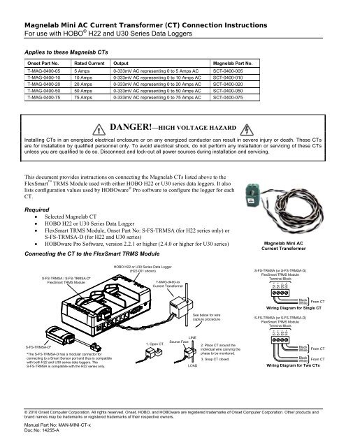
<strong>Magnelab</strong> <strong>Mini</strong> <strong>AC</strong> Current Transformer (<strong>CT</strong>) <strong>Connection</strong> <strong>Instructions</strong><br />
For use with HOBO ® H22 and U30 Series Data Loggers<br />
Applies to these <strong>Magnelab</strong> <strong>CT</strong>s<br />
Onset Part No. Rated Current Output <strong>Magnelab</strong> Part No.<br />
T-MAG-0400-05 5 Amps 0-333mV <strong>AC</strong> representing 0 to 5 Amps <strong>AC</strong> S<strong>CT</strong>-0400-005<br />
T-MAG-0400-10 10 Amps 0-333mV <strong>AC</strong> representing 0 to 10 Amps <strong>AC</strong> S<strong>CT</strong>-0400-010<br />
T-MAG-0400-20 20 Amps 0-333mV <strong>AC</strong> representing 0 to 20 Amps <strong>AC</strong> S<strong>CT</strong>-0400-020<br />
T-MAG-0400-50 50 Amps 0-333mV <strong>AC</strong> representing 0 to 50 Amps <strong>AC</strong> S<strong>CT</strong>-0400-050<br />
T-MAG-0400-75 75 Amps 0-333mV <strong>AC</strong> representing 0 to 75 Amps <strong>AC</strong> S<strong>CT</strong>-0400-075<br />
DANGER!—HIGH VOLTAGE HAZARD<br />
Installing <strong>CT</strong>s in an energized electrical enclosure or on any energized conductor can result in severe injury or death. These <strong>CT</strong>s<br />
are for installation by qualified personnel only. To avoid electrical shock, do not perform any installation or servicing of these <strong>CT</strong>s<br />
unless you are qualified to do so. Disconnect and lock-out all power sources during installation and servicing.<br />
This document provides instructions on connecting the <strong>Magnelab</strong> <strong>CT</strong>s listed above to the<br />
FlexSmart TRMS Module used with either HOBO H22 or U30 series data loggers. It also<br />
lists configuration values used by HOBOware ® Pro software to configure the logger for each<br />
<strong>CT</strong>.<br />
Required<br />
• Selected <strong>Magnelab</strong> <strong>CT</strong><br />
• HOBO H22 or U30 Series Data Logger<br />
• FlexSmart TRMS Module, Onset Part No: S-FS-TRMSA (for H22 series only) or<br />
S-FS-TRMSA-D (for H22 and U30 series)<br />
• HOBOware Pro Software, version 2.2.1 or higher (2.4.0 or higher for U30 series)<br />
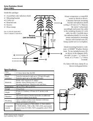
Connecting the <strong>CT</strong> to the FlexSmart TRMS Module<br />
<strong>Magnelab</strong> <strong>Mini</strong> <strong>AC</strong><br />
Current Transformer<br />
S-FS-TRMSA / S-FS-TRMSA-D*<br />
FlexSmart TRMS Module<br />
HOBO H22 or U30 Series Data Logger<br />
(H22-001 shown)<br />
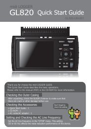
T-MAG-0400-xx<br />
Current Transformer<br />
S-FS-TRMSA (or S-FS-TRMSA-D)<br />
FlexSmart TRMS Module<br />
Terminal Block<br />
S1~<br />
S1~<br />
S2~<br />
S2~<br />
See below for wire<br />
capture procedure<br />
Black<br />
White<br />
From <strong>CT</strong><br />
Wiring Diagram for Single <strong>CT</strong><br />
S-FS-TRMSA (or S-FS-TRMSA-D)<br />
FlexSmart TRMS Module<br />
Terminal Block<br />
S-FS-TRMSA-D*<br />
*The S-FS-TRMSA-D has a modular connector for<br />
connecting to a Smart Sensor port and thus is compatible<br />
with both H22 and U30 series data loggers. The<br />
S-FS-TRMSA is compatible with the H22 series only.<br />
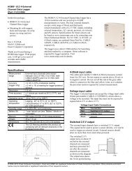
1. Open <strong>CT</strong>.<br />
LINE<br />
Source Face<br />
LOAD<br />
2. Place <strong>CT</strong> around the<br />
individual wire carrying the<br />
phase to be monitored.<br />
3. Snap <strong>CT</strong> closed.<br />
S1~<br />
S1~<br />
S2~<br />
S2~<br />
Black<br />
White<br />
From <strong>CT</strong><br />
Black<br />
White<br />
From <strong>CT</strong><br />
Wiring Diagram for Two <strong>CT</strong>s<br />
© 2010 Onset Computer Corporation. All rights reserved. Onset, HOBO, and HOBOware are registered trademarks of Onset Computer Corporation. Other products and<br />
brand names may be trademarks or registered trademarks of their respective owners.<br />
Manual Part No: MAN-MINI-<strong>CT</strong>-x<br />
Doc No: 14255-A
<strong>Magnelab</strong> <strong>Mini</strong> <strong>AC</strong> Current Transducer (<strong>CT</strong>) <strong>Connection</strong> <strong>Instructions</strong><br />
Configuring the Data Logger for the <strong>CT</strong>, using HOBOware Pro Software<br />
HOBOware Pro software provides configuration files for the <strong>CT</strong>s. The table below lists the recommended configuration values for<br />
each <strong>CT</strong> that these files contain. For information on loading configuration files, refer to the software documentation.<br />
Onset Part No: Channel Name Raw Value 1 (mV) Raw Value 2 (mV) Scaled Value 1 Scaled Value 2 Scaled Units<br />
T-MAG-0400-05 Current 0 333 0 5 A<br />
T-MAG-0400-10 Current 0 333 0 10 A<br />
T-MAG-0400-20 Current 0 333 0 20 A<br />
T-MAG-0400-50 Current 0 333 0 50 A<br />
T-MAG-0400-75 Current 0 333 0 75 A<br />
2