
You also want an ePaper? Increase the reach of your titles
YUMPU automatically turns print PDFs into web optimized ePapers that Google loves.
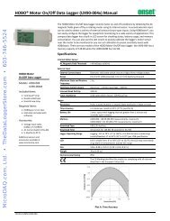
<strong>HOBO</strong> ® <strong>U12</strong> 4-External<br />
Channel Data Logger<br />
(Part # <strong>U12</strong>-<strong>006</strong>)<br />
Inside this package:<br />
• <strong>HOBO</strong> <strong>U12</strong> 4-External<br />
Channel Data Logger<br />
• Mounting kit with magnet,<br />
hook and loop tape, tie-wrap<br />
mount, tie wrap, and two<br />
screws.<br />
Doc # 13125-B,<br />
MAN-<strong>U12</strong><strong>006</strong>-web<br />
Onset Computer Corporation<br />
Thank you for purchasing a<br />
<strong>HOBO</strong> <strong>data</strong> <strong>logger</strong>. With proper<br />
care, it will give you years of<br />
accurate and reliable<br />
measurements.<br />
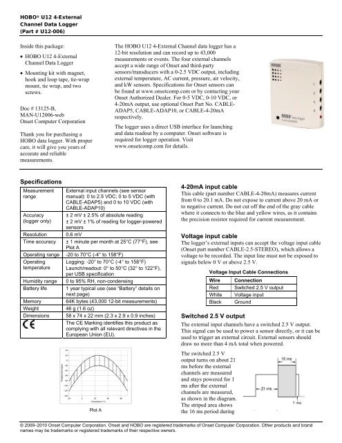
The <strong>HOBO</strong> <strong>U12</strong> 4-External Channel <strong>data</strong> <strong>logger</strong> has a<br />
12-bit resolution and can record up to 43,000<br />
measurements or events. The four external channels<br />
accept a wide range of Onset and third-party<br />
sensors/transducers with a 0-2.5 VDC output, including<br />
external temperature, AC current, pressure, air velocity,<br />
and kW sensors. Specifications for Onset sensors can<br />
be found at www.onsetcomp.com or by contacting your<br />
Onset Authorized Dealer. For 0-5 VDC, 0-10 VDC, or<br />
4-20mA output, use optional Onset Part No. CABLE-<br />
ADAP5, CABLE-ADAP10, or CABLE-4-20mA<br />
respectively.<br />
The <strong>logger</strong> uses a direct USB interface for launching<br />
and <strong>data</strong> readout by a computer. Onset software is<br />
required for <strong>logger</strong> operation. Visit<br />
www.onsetcomp.com for details.<br />
Specifications<br />
Measurement<br />
range<br />
Accuracy<br />
(<strong>logger</strong> only)<br />
Resolution<br />
Time accuracy<br />
Operating range<br />
Operating<br />
temperature<br />
Humidity range<br />
Battery life<br />
Memory<br />
Weight<br />
Dimensions<br />
External input channels (see sensor<br />
manual): 0 to 2.5 VDC; 0 to 5 VDC (with<br />
CABLE-ADAP5) and 0 to 10 VDC (with<br />
CABLE-ADAP10)<br />
± 2 mV ± 2.5% of absolute reading<br />
± 2 mV ± 1% of reading for <strong>logger</strong>-powered<br />
sensors<br />
0.6 mV<br />
± 1 minute per month at 25°C (77°F), see<br />
Plot A<br />
-20 to 70°C (-4° to 158°F)<br />
Logging: -20° to 70°C (-4° to 158°F)<br />
Launch/readout: 0° to 50°C (32° to 122°F),<br />
per USB specification<br />
0 to 95% RH, non-condensing<br />
1 year typical use (see “Battery” details on<br />
next page)<br />
64K bytes (43,000 12-bit measurements)<br />
46 g (1.6 oz)<br />
58 x 74 x 22 mm (2.3 x 2.9 x 0.9 inches)<br />
The CE Marking identifies this product as<br />
complying with all relevant directives in the<br />
European Union (EU).<br />
Plot A<br />
4-20mA input cable<br />
This cable (part number CABLE-4-20mA) measures current<br />
from 0 to 20.1 mA. Do not expose to current above 20 mA or<br />
to negative current. Do not cut off the end of the gray cable<br />
where it connects to the blue and yellow wires, as it contains<br />
the precision resistor required for current measurement.<br />
Voltage input cable<br />
The <strong>logger</strong>’s external inputs can accept the voltage input cable<br />
(Onset part number CABLE-2.5-STEREO), which allows a<br />
voltage to be recorded. The input line must not be exposed to<br />
signals below 0 V or above 2.5 V.<br />
Voltage Input Cable Connections<br />
Wire Connection<br />
Red Switched 2.5 V output<br />
White Voltage input<br />
Black Ground<br />
Switched 2.5 V output<br />
The external input channels have a switched 2.5 V output.<br />
This signal can be used to power a sensor directly, or it can be<br />
used to trigger an external circuit. External sensors should<br />
draw no more than 4 mA total when powered.<br />
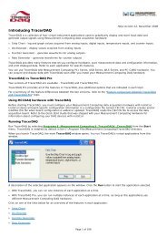
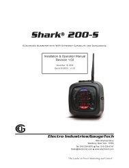
The switched 2.5 V<br />
output turns on about 21<br />
ms before the external<br />
channels are measured<br />
and stays powered for 1<br />
ms after the external<br />
channels are measured,<br />
as shown in the diagram.<br />
The striped area shows<br />
the 16 ms period during<br />
© 2009–2010 Onset Computer Corporation. Onset and <strong>HOBO</strong> are registered trademarks of Onset Computer Corporation. Other products and brand<br />
names may be trademarks or registered trademarks of their respective owners.
<strong>HOBO</strong> <strong>U12</strong> 4-External Channel Data Logger<br />
which the <strong>logger</strong> samples the input signals.<br />
When using multiple voltage and/or current inputs, the (-)<br />
from your current source(s) and the 0 V line of your voltage<br />
source(s) are tied together at the <strong>logger</strong>. If these lines are at<br />
different voltage potentials, this may cause inaccurate readings<br />
or even damage your <strong>logger</strong>. Keep in mind that these lines<br />
may also be tied to earth ground through your PC interface<br />
cable when connected to your computer. Special precautions<br />
may be necessary if any of your voltage or current source<br />
common lines are not tied to earth ground. Input isolators may<br />
be needed in industrial environments to prevent errors caused<br />
by ground loops.<br />
CAUTION: Analog channel input cannot exceed 2.5<br />
VDC. For sensor outputs up to 10 VDC, use<br />
appropriate voltage adapter cable.<br />
Other external sensors<br />
Onset has a range of external temperature sensors, AC current<br />
sensors, and cables for incorporating other sensors that are<br />
compatible with the <strong>U12</strong> 4-External Channel Data Logger.<br />
Measurement specifications for using Onset temperature and<br />
AC current sensors with this <strong>logger</strong> are provided in the sensor<br />
manuals. Visit www.onsetcomp.com for details on compatible<br />
sensors.<br />
Connecting the <strong>logger</strong><br />
The U-Family <strong>logger</strong> requires an Onset-supplied USB<br />
interface cable to connect to the computer. If possible, avoid<br />
connecting at temperatures below 0°C (32°F) or above 50°C<br />
(122°F).<br />
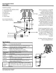
1. Plug the large end of the USB interface cable into a USB<br />
port on the computer.<br />
2. Plug the small end of the USB interface cable into the<br />
bottom of the <strong>logger</strong>, as shown in the following diagram.<br />
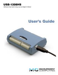
Important: Press this<br />
button for 3 seconds<br />
when <strong>logger</strong> is<br />
launched with Button<br />
Start or press for<br />
1 second to record<br />
an event while logging<br />
USB interface<br />
cable plugged<br />
into <strong>logger</strong><br />
activate the external channels in the <strong>logger</strong> software when<br />
configuring the launch. Important: If you select an external<br />
channel, but do not plug the probe in, false <strong>data</strong> will be<br />
recorded for that channel.<br />
You can read out the <strong>logger</strong> while it continues to log, stop it<br />
manually with the software, or let it record <strong>data</strong> until the<br />
memory is full.<br />
Refer to the software user’s guide for complete details on<br />
launching, reading out, and viewing <strong>data</strong> from the <strong>logger</strong>.<br />
Protecting the <strong>logger</strong><br />
The <strong>logger</strong> can be permanently damaged by corrosion if it gets<br />
wet. Protect it from condensation. If it gets wet, remove the<br />
battery immediately and dry the circuit board with a hair dryer<br />
before reinstalling the battery. Do not let the board get too hot.<br />
You should be able to comfortably hold the board in your<br />
hand while drying.<br />
Note! Static electricity may cause the <strong>logger</strong> to stop<br />
logging. To avoid electrostatic discharge, transport the <strong>logger</strong><br />
in an anti-static bag, and ground yourself by touching an<br />
unpainted metal surface before handling the <strong>logger</strong>. For more<br />
information about electrostatic discharge, visit our website at<br />
http://www.onsetcomp.com/Support/support.html.<br />
Sample and event logging<br />
The <strong>logger</strong> can record two types of <strong>data</strong>: samples and events.<br />
Samples are the sensor measurements recorded at each<br />
logging interval (for example, the temperature every minute).<br />
Events are independent occurrences triggered by a <strong>logger</strong><br />
activity. Examples of events recorded asynchronously during<br />
deployment include when the <strong>logger</strong> is connected to the host,<br />
when the battery is low, the end of a <strong>data</strong> file once the <strong>logger</strong><br />
is stopped, and button pushes.<br />
Press and hold down the button on the front of the <strong>logger</strong> for<br />
at least one second to record an event. Both a button up and<br />
down event will be recorded. This is useful if you want to<br />
mark the <strong>data</strong>file at a particular point. For example, if the<br />
<strong>logger</strong> is located in an incubator, you might press the button<br />
each time the door is opened.<br />
The <strong>logger</strong> stores 64K of <strong>data</strong>, and can record up to 43,000<br />
samples and events combined.<br />
Operation<br />
A light (LED) on the side of the <strong>logger</strong> confirms <strong>logger</strong><br />
operation.<br />
If the <strong>logger</strong> has never been connected to the computer before,<br />
it may take a few seconds for the new hardware to be detected.<br />
Use the <strong>logger</strong> software to launch and read out the <strong>logger</strong>.<br />
Important: If you configure the <strong>logger</strong> to start with a<br />
button start, be sure to press and hold down the button on<br />
the front of the <strong>logger</strong> for at least three seconds when you<br />
want to begin logging <strong>data</strong>.<br />
Be sure to plug the external sensors into the side of the <strong>logger</strong><br />
before logging begins. Also select the correct sensors and<br />
Channel 1<br />
Channel 2<br />
Channel 3<br />
Channel 4<br />
Light (LED)<br />
2
<strong>HOBO</strong> <strong>U12</strong> 4-External Channel Data Logger<br />
The following table explains when the <strong>logger</strong> blinks during<br />
<strong>logger</strong> operation:<br />
When:<br />
The <strong>logger</strong> is logging<br />
The <strong>logger</strong> is awaiting a<br />
start because it was<br />
launched in Start At<br />
Interval, Delayed Start,<br />
or Button Start mode<br />
The button on the <strong>logger</strong><br />
is being pushed for a<br />
Button Start launch<br />
The light:<br />
Blinks once every one to four<br />
seconds (the shorter the logging<br />
interval, the faster the light<br />
blinks); blinks when logging a<br />
sample<br />
Blinks once every eight seconds<br />
until launch begins<br />
Blinks once every second while<br />
pressing the button and then<br />
flashes rapidly once you release<br />
the button. The light then reverts<br />
to a blinking pattern based on the<br />
logging interval<br />
Mounting<br />
There are four ways to mount the <strong>logger</strong> using the materials in<br />
the mounting kit included with the <strong>logger</strong>:<br />
• Use the hook and loop tape to affix<br />
the <strong>logger</strong> to a surface.<br />
• Attach the magnet, then place the<br />
<strong>logger</strong> on a magnetic surface.<br />
• Use the tie wrap and tie wrap mount<br />
to tie the <strong>logger</strong> to an object.<br />
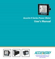
• Fasten the <strong>logger</strong> to a surface with the<br />
two Phillips-head screws. The back of<br />
32 mm<br />
(1¼ inch)<br />
the <strong>logger</strong> has two inserts for the screws, 32 mm (1¼<br />
inches) apart.<br />
Battery<br />
The <strong>logger</strong> requires one 3-Volt CR-2032 lithium battery.<br />
Expected battery life varies based on the temperature and the<br />
frequency at which the <strong>logger</strong> is recording <strong>data</strong> (the logging<br />
interval). A new battery will typically last one year with<br />
logging intervals greater than one minute. Deployments in<br />
extremely cold or hot temperatures or logging intervals faster<br />
than one minute may significantly reduce battery life. Onset<br />
recommends that you install a fresh battery before every<br />
deployment if temperatures below 0°C (32°F) are expected.<br />
To replace the battery:<br />
1. Disconnect the <strong>logger</strong> from the computer.<br />
2. Unscrew the <strong>logger</strong> case.<br />
3. Lift the circuit board and carefully push the battery out<br />
with a small blunt instrument, or pull it out with your<br />
fingernail.<br />
4. Insert a new battery, positive side facing up.<br />
5. Carefully realign the <strong>logger</strong> case and re-fasten the screws.<br />
WARNING: Do not cut open, incinerate, heat above<br />
85°C (185°F), or recharge the lithium battery. The<br />
battery may explode if the <strong>logger</strong> is exposed to extreme<br />
heat or conditions that could damage or destroy the<br />
battery case. Do not dispose of the <strong>logger</strong> or battery in<br />
fire. Do not expose the contents of the battery to water.<br />
Dispose of the battery according to local regulations for<br />
lithium batteries.<br />
3