
You also want an ePaper? Increase the reach of your titles
YUMPU automatically turns print PDFs into web optimized ePapers that Google loves.
<strong>HOBO</strong> <strong>U12</strong> 4-External Channel Data Logger<br />
which the <strong>logger</strong> samples the input signals.<br />
When using multiple voltage and/or current inputs, the (-)<br />
from your current source(s) and the 0 V line of your voltage<br />
source(s) are tied together at the <strong>logger</strong>. If these lines are at<br />
different voltage potentials, this may cause inaccurate readings<br />
or even damage your <strong>logger</strong>. Keep in mind that these lines<br />
may also be tied to earth ground through your PC interface<br />
cable when connected to your computer. Special precautions<br />
may be necessary if any of your voltage or current source<br />
common lines are not tied to earth ground. Input isolators may<br />
be needed in industrial environments to prevent errors caused<br />
by ground loops.<br />
CAUTION: Analog channel input cannot exceed 2.5<br />
VDC. For sensor outputs up to 10 VDC, use<br />
appropriate voltage adapter cable.<br />
Other external sensors<br />
Onset has a range of external temperature sensors, AC current<br />
sensors, and cables for incorporating other sensors that are<br />
compatible with the <strong>U12</strong> 4-External Channel Data Logger.<br />
Measurement specifications for using Onset temperature and<br />
AC current sensors with this <strong>logger</strong> are provided in the sensor<br />
manuals. Visit www.onsetcomp.com for details on compatible<br />
sensors.<br />
Connecting the <strong>logger</strong><br />
The U-Family <strong>logger</strong> requires an Onset-supplied USB<br />
interface cable to connect to the computer. If possible, avoid<br />
connecting at temperatures below 0°C (32°F) or above 50°C<br />
(122°F).<br />
1. Plug the large end of the USB interface cable into a USB<br />
port on the computer.<br />
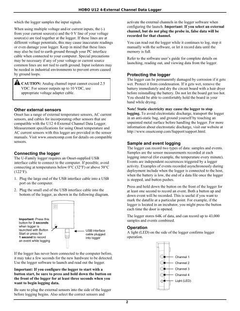
2. Plug the small end of the USB interface cable into the<br />
bottom of the <strong>logger</strong>, as shown in the following diagram.<br />
Important: Press this<br />
button for 3 seconds<br />
when <strong>logger</strong> is<br />
launched with Button<br />
Start or press for<br />
1 second to record<br />
an event while logging<br />
USB interface<br />
cable plugged<br />
into <strong>logger</strong><br />
activate the external channels in the <strong>logger</strong> software when<br />
configuring the launch. Important: If you select an external<br />
channel, but do not plug the probe in, false <strong>data</strong> will be<br />
recorded for that channel.<br />
You can read out the <strong>logger</strong> while it continues to log, stop it<br />
manually with the software, or let it record <strong>data</strong> until the<br />
memory is full.<br />
Refer to the software user’s guide for complete details on<br />
launching, reading out, and viewing <strong>data</strong> from the <strong>logger</strong>.<br />
Protecting the <strong>logger</strong><br />
The <strong>logger</strong> can be permanently damaged by corrosion if it gets<br />
wet. Protect it from condensation. If it gets wet, remove the<br />
battery immediately and dry the circuit board with a hair dryer<br />
before reinstalling the battery. Do not let the board get too hot.<br />
You should be able to comfortably hold the board in your<br />
hand while drying.<br />
Note! Static electricity may cause the <strong>logger</strong> to stop<br />
logging. To avoid electrostatic discharge, transport the <strong>logger</strong><br />
in an anti-static bag, and ground yourself by touching an<br />
unpainted metal surface before handling the <strong>logger</strong>. For more<br />
information about electrostatic discharge, visit our website at<br />
http://www.onsetcomp.com/Support/support.html.<br />
Sample and event logging<br />
The <strong>logger</strong> can record two types of <strong>data</strong>: samples and events.<br />
Samples are the sensor measurements recorded at each<br />
logging interval (for example, the temperature every minute).<br />
Events are independent occurrences triggered by a <strong>logger</strong><br />
activity. Examples of events recorded asynchronously during<br />
deployment include when the <strong>logger</strong> is connected to the host,<br />
when the battery is low, the end of a <strong>data</strong> file once the <strong>logger</strong><br />
is stopped, and button pushes.<br />
Press and hold down the button on the front of the <strong>logger</strong> for<br />
at least one second to record an event. Both a button up and<br />
down event will be recorded. This is useful if you want to<br />
mark the <strong>data</strong>file at a particular point. For example, if the<br />
<strong>logger</strong> is located in an incubator, you might press the button<br />
each time the door is opened.<br />
The <strong>logger</strong> stores 64K of <strong>data</strong>, and can record up to 43,000<br />
samples and events combined.<br />
Operation<br />
A light (LED) on the side of the <strong>logger</strong> confirms <strong>logger</strong><br />
operation.<br />
If the <strong>logger</strong> has never been connected to the computer before,<br />
it may take a few seconds for the new hardware to be detected.<br />
Use the <strong>logger</strong> software to launch and read out the <strong>logger</strong>.<br />
Important: If you configure the <strong>logger</strong> to start with a<br />
button start, be sure to press and hold down the button on<br />
the front of the <strong>logger</strong> for at least three seconds when you<br />
want to begin logging <strong>data</strong>.<br />
Be sure to plug the external sensors into the side of the <strong>logger</strong><br />
before logging begins. Also select the correct sensors and<br />
Channel 1<br />
Channel 2<br />
Channel 3<br />
Channel 4<br />
Light (LED)<br />
2