HOBO Motor On/Off Data Logger (UX90-004x ... - MicroDAQ.com
HOBO Motor On/Off Data Logger (UX90-004x ... - MicroDAQ.com
HOBO Motor On/Off Data Logger (UX90-004x ... - MicroDAQ.com

Create successful ePaper yourself
Turn your PDF publications into a flip-book with our unique Google optimized e-Paper software.
<strong>HOBO</strong>® <strong>Motor</strong> <strong>On</strong>/<strong>Off</strong> <strong>Data</strong> <strong>Logger</strong> (<strong>UX90</strong>-<strong>004x</strong>) Manual<br />
<strong>MicroDAQ</strong>.<strong>com</strong>, Ltd. • The<strong>Data</strong><strong>Logger</strong>Store.<strong>com</strong> • 603-746-5524<br />
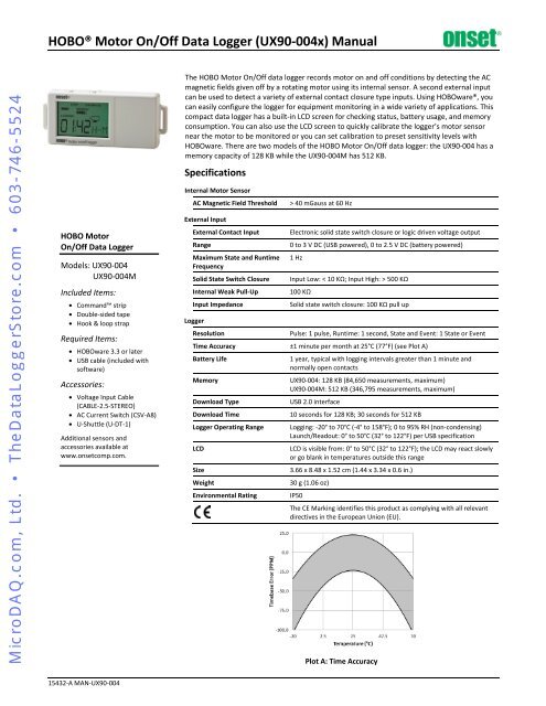
<strong>HOBO</strong> <strong>Motor</strong><br />
<strong>On</strong>/<strong>Off</strong> <strong>Data</strong> <strong>Logger</strong><br />
Models: <strong>UX90</strong>-004<br />
<strong>UX90</strong>-004M<br />
Included Items:<br />
• Command strip<br />
• Double-sided tape<br />
• Hook & loop strap<br />
Required Items:<br />
• <strong>HOBO</strong>ware 3.3 or later<br />
• USB cable (included with<br />
software)<br />
Accessories:<br />
• Voltage Input Cable<br />
(CABLE-2.5-STEREO)<br />
• AC Current Switch (CSV-A8)<br />
• U-Shuttle (U-DT-1)<br />
Additional sensors and<br />
accessories available at<br />
www.onset<strong>com</strong>p.<strong>com</strong>.<br />
The <strong>HOBO</strong> <strong>Motor</strong> <strong>On</strong>/<strong>Off</strong> data logger records motor on and off conditions by detecting the AC<br />
magnetic fields given off by a rotating motor using its internal sensor. A second external input<br />
can be used to detect a variety of external contact closure type inputs. Using <strong>HOBO</strong>ware®, you<br />
can easily configure the logger for equipment monitoring in a wide variety of applications. This<br />
<strong>com</strong>pact data logger has a built-in LCD screen for checking status, battery usage, and memory<br />
consumption. You can also use the LCD screen to quickly calibrate the logger’s motor sensor<br />
near the motor to be monitored or you can set calibration to preset sensitivity levels with<br />
<strong>HOBO</strong>ware. There are two models of the <strong>HOBO</strong> <strong>Motor</strong> <strong>On</strong>/<strong>Off</strong> data logger: the <strong>UX90</strong>-004 has a<br />
memory capacity of 128 KB while the <strong>UX90</strong>-004M has 512 KB.<br />
Specifications<br />
Internal <strong>Motor</strong> Sensor<br />
AC Magnetic Field Threshold<br />
External Input<br />
External Contact Input<br />
Range<br />
Maximum State and Runtime<br />
Frequency<br />
Solid State Switch Closure<br />
Internal Weak Pull-Up<br />
Input Impedance<br />
<strong>Logger</strong><br />
Resolution<br />
> 40 mGauss at 60 Hz<br />
Electronic solid state switch closure or logic driven voltage output<br />
0 to 3 V DC (USB powered), 0 to 2.5 V DC (battery powered)<br />
1 Hz<br />
Input Low: < 10 KΩ; Input High: > 500 KΩ<br />
100 KΩ<br />
Solid state switch closure: 100 KΩ pull up<br />
Pulse: 1 pulse, Runtime: 1 second, State and Event: 1 State or Event<br />
Time Accuracy ±1 minute per month at 25°C (77°F) (see Plot A)<br />
Battery Life<br />
Memory<br />
Download Type<br />
Download Time<br />
<strong>Logger</strong> Operating Range<br />
LCD<br />
Size<br />
Weight<br />
Environmental Rating<br />
1 year, typical with logging intervals greater than 1 minute and<br />
normally open contacts<br />
<strong>UX90</strong>-004: 128 KB (84,650 measurements, maximum)<br />
<strong>UX90</strong>-004M: 512 KB (346,795 measurements, maximum)<br />
USB 2.0 interface<br />
10 seconds for 128 KB; 30 seconds for 512 KB<br />
Logging: -20° to 70°C (-4° to 158°F); 0 to 95% RH (non-condensing)<br />
Launch/Readout: 0° to 50°C (32° to 122°F) per USB specification<br />
LCD is visible from: 0° to 50°C (32° to 122°F); the LCD may react slowly<br />
or go blank in temperatures outside this range<br />
3.66 x 8.48 x 1.52 cm (1.44 x 3.34 x 0.6 in.)<br />
30 g (1.06 oz)<br />
IP50<br />
The CE Marking identifies this product as <strong>com</strong>plying with all relevant<br />
directives in the European Union (EU).<br />
Plot A: Time Accuracy<br />
15432-A MAN-<strong>UX90</strong>-004
<strong>HOBO</strong> <strong>Motor</strong> <strong>On</strong>/<strong>Off</strong> <strong>Data</strong> <strong>Logger</strong> (<strong>UX90</strong>-<strong>004x</strong>) Manual<br />
<strong>MicroDAQ</strong>.<strong>com</strong>, Ltd. • The<strong>Data</strong><strong>Logger</strong>Store.<strong>com</strong> • 603-746-5524<br />
LCD Screen<br />
Mounting<br />
Loop<br />
<strong>Logger</strong> Components and Operation<br />
Start/Stop Button<br />
USB Port<br />
Battery Door<br />
External<br />
Input Jack<br />
Calibration Button<br />
<strong>Motor</strong> Sensor<br />
(inside the case)<br />
Start/Stop Button: Press this button for 3 seconds to start or<br />
stop logging data. This requires configuring the logger in<br />
<strong>HOBO</strong>ware with a push button start or stop (see Setting up the<br />
<strong>Logger</strong>). You can also press this button for 1 second to record<br />
an internal event (see Recording Internal <strong>Logger</strong> Events) or to<br />
turn the LCD screen on if the option to turn off the LCD has<br />
been enabled (see Setting up the <strong>Logger</strong>).<br />
Battery Door: Open the battery door (not visible in the<br />
diagram) on the top of the logger to access the logger battery<br />
(see Battery Information).<br />
Calibration Button: Press this button to calibrate the logger for<br />
the motor you will be monitoring. See Calibrating the <strong>Motor</strong><br />
Sensor for more details.<br />
Mounting Loops: Use the two mounting loops to mount the<br />
logger with the hook-and-loop strapping (see Mounting the<br />
<strong>Logger</strong>).<br />
<strong>Motor</strong> Sensor: This built-in sensor located inside the logger<br />
case monitors motor on and off conditions.<br />
External Input Jack: Use this jack to attach a supported sensor<br />
(see Connecting External Sensors).<br />
USB Port: Use this port to connect the logger to the <strong>com</strong>puter<br />
or the <strong>HOBO</strong> U-Shuttle via USB cable (see Setting up the <strong>Logger</strong><br />
and Reading Out the <strong>Logger</strong>).<br />
LCD Screen: This logger is equipped with an LCD screen that<br />
displays details about the current status of the logger.<br />
Mounting<br />
Loop<br />
The following table lists the symbols shown on the LCD screen:<br />
LCD Symbol<br />
Description<br />
The logger is waiting to be launched. Press and<br />
hold the Start/Stop button for 3 seconds to launch<br />
the logger.<br />
The logger has been launched with a push button<br />
stop enabled; press and hold the Start/Stop<br />
button for 3 seconds to stop the logger. Note: If<br />
you also launched the logger with a push button<br />
Start, this symbol will not appear on the display<br />
for 5 minutes.<br />
The battery indicator shows the approximate<br />
battery power remaining.<br />
If the logger has been configured to stop logging<br />
when memory fills, the memory bar indicates the<br />
approximate space remaining in the logger to<br />
record data. In this example, the logger memory is<br />
almost full.<br />
If the logger has been configured to never stop<br />
logging (wrapping enabled), then a single block<br />
will blink starting at the left and moving right over<br />
time. Each block represents a segment of memory<br />
where the data is being recorded. In this example,<br />
the middle block is blinking.<br />
The motor is off (internal sensor).<br />
The motor is on (internal sensor).<br />
The switch is open (external sensor).<br />
The switch is closed (external sensor).<br />
The logger can be calibrated. See Calibrating the<br />
<strong>Motor</strong> Sensor for more details.<br />
This shows the signal strength of the motor being<br />
monitored. In this example, the signal strength is<br />
at full scale. See Calibrating the <strong>Motor</strong> Sensor for<br />
more details.<br />
The logger is currently logging.<br />
Time display when logger is logging:<br />
This shows the total amount of time the motor has<br />
been on or switch has been closed since logging<br />
began, ranging from seconds to days. This example<br />
indicates the motor has been on or the switch has<br />
been closed for a total of 5 minutes and 38<br />
seconds. The logger must be launched with the<br />
LCD set to show “Time” for this symbol to display.<br />
Time display when logger is stopped:<br />
This indicates the logger has been configured to<br />
start logging on a particular date/time. The display<br />
will count down to the start date/time until<br />
logging begins. In this example, 5 minutes and 38<br />
seconds remain until logging will begin.<br />
This shows the percentage of time the motor has<br />
been on or the switch has been closed since<br />
logging began. This example indicates the motor<br />
has been on or the switch has been closed for a<br />
total of 24% of the time since logging began. The<br />
logger must be launched with the LCD set to show<br />
“%” for this symbol to display.<br />
The logger has been stopped.<br />
1-800-LOGGERS 2 www.onset<strong>com</strong>p.<strong>com</strong>
<strong>HOBO</strong> <strong>Motor</strong> <strong>On</strong>/<strong>Off</strong> <strong>Data</strong> <strong>Logger</strong> (<strong>UX90</strong>-<strong>004x</strong>) Manual<br />
<strong>MicroDAQ</strong>.<strong>com</strong>, Ltd. • The<strong>Data</strong><strong>Logger</strong>Store.<strong>com</strong> • 603-746-5524<br />
Notes:<br />
• You can disable the LCD screen when logging. Select “Turn<br />
LCD <strong>Off</strong>” when setting up the logger as described in the<br />
next section. When this option is enabled, you can still<br />
temporarily view the LCD screen by pushing the Start/Stop<br />
button or Calibration for 1 second. The LCD will then<br />
remain on for 10 minutes.<br />
• When the logger has stopped logging, the LCD screen will<br />
remain on until the logger is offloaded to a <strong>com</strong>puter or<br />
<strong>HOBO</strong> U-Shuttle (unless launched with the “Turn LCD <strong>Off</strong>”<br />
option). <strong>On</strong>ce the logger has been offloaded and<br />
disconnected from the <strong>com</strong>puter, the LCD will turn off<br />
automatically after 2 hours. The LCD will turn back on the<br />
next time the logger is connected to the <strong>com</strong>puter.<br />
Setting up the <strong>Logger</strong><br />
Use <strong>HOBO</strong>ware to set up the logger, including selecting the<br />
start and stop logging options, configuring the sensors, and<br />
entering scaling factors as necessary. It may be helpful to set up<br />
the logger to start at a specific date/time or with a push button<br />
stop and then bring it to the location where you will mount it to<br />
connect any external devices and test the connections before<br />
logging begins.<br />
1. Connect the logger and open the Launch <strong>Logger</strong> window. To<br />
connect the logger to a <strong>com</strong>puter, plug the small end of the<br />
USB cable into the side of the logger and the large end into a<br />
USB port on the <strong>com</strong>puter. Click the Launch icon on the<br />
<strong>HOBO</strong>ware toolbar or select Launch from the Device menu.<br />
Important: USB 2.0 specifications do not guarantee<br />
operation outside the range of 0°C (32°F) to 50°C (122°F).<br />
2. Configure the sensor. Choose either the internal or external<br />
sensor and enter the name and select the state description<br />
as necessary. The sensor can be configured to log:<br />
• State. This records how long an event lasts by storing the<br />
date and time when the state or switch changes (logic<br />
state high to low or low to high). The logger checks every<br />
second for a state change, but will only record a timestamped<br />
value when the state change occurs. <strong>On</strong>e state<br />
change to the next represents the event duration.<br />
• Runtime. The logger checks the state of the line once<br />
every second. At the end of each logging interval, the<br />
logger records how many seconds the line was in the logic<br />
low state.<br />
3. Choose a calibration method with the Advanced settings.<br />
The default method is to calibrate the logger using the<br />
calibrate button on the logger after it is launched. If you<br />
need to specify the sensitivity used for calibration, then click<br />
the Advanced button and select either a maximum or<br />
minimum level. See Calibrating the <strong>Motor</strong> Sensor for more<br />
details.<br />
4. Configure optional filters as necessary. Click the Filter<br />
button to create additional filtered data series based on the<br />
sensor configuration. Any filtered series will be automatically<br />
available upon reading out the logger.<br />
5. Set the units to display on the LCD screen. Select either<br />
Time or %. For external sensors, you can either use the<br />
default units or enter your own units up to three characters.<br />
6. If the logger is configured to record runtime, choose a<br />
logging interval from 1 second to a maximum of 18 hours,<br />
12 minutes, and 15 seconds.<br />
7. Choose when to start logging:<br />
• Now. Logging begins immediately.<br />
• At Interval. Logging will begin at the next even interval<br />
(available when logging runtime only).<br />
• <strong>On</strong> Date/Time. Logging will begin at a date and time you<br />
specify.<br />
• Push Button. Logging will begin once you press the<br />
Start/Stop logging button for 3 seconds.<br />
8. Choose when to stop logging:<br />
• When Memory Fills. Logging will end once the logger<br />
memory is full.<br />
• Never (Wrapping). The logger will continue recording data<br />
indefinitely, with newest data overwriting the oldest.<br />
• Push Button. Logging will end once you press the<br />
Start/Stop logging button for 3 seconds. Note that if you<br />
also choose Push Button to start logging, then you will not<br />
be able to stop logging until 5 minutes after logging<br />
begins.<br />
• Specific Stop Time. Logging will end at a date and time<br />
you specify.<br />
9. Select any other logging options as desired and click Start to<br />
finish the launch configuration. The status of the launch will<br />
be displayed on the LCD screen, unless you select the option<br />
to “Turn LCD off.”<br />
Determining Logging Duration <strong>Data</strong><br />
The logger’s storage capacity and logging duration depends on<br />
the interval between state changes and events. The longer the<br />
interval between state changes, the more memory is needed to<br />
store each data point. The following table shows how memory<br />
capacity is affected by the amount of time between events:<br />
Time<br />
Between<br />
Events<br />
1 to 15<br />
seconds<br />
16<br />
seconds<br />
to 4.25<br />
minutes<br />
4.26 to<br />
68.25<br />
minutes<br />
68.26<br />
minutes<br />
to 18.2<br />
hours<br />
Approximate<br />
Total <strong>Data</strong><br />
Points<br />
Approximate<br />
Logging Duration<br />
(1 Year Battery Life)<br />
84,650 23.51 hours to 14.7<br />
days<br />
<strong>Logger</strong> Part<br />
Number<br />
<strong>UX90</strong>-004<br />
346,795 4.01 to 60.21 days <strong>UX90</strong>-004M<br />
63,488 11.76 to 187.38 days <strong>UX90</strong>-004<br />
260,096 48.17 days to 2.1 years <strong>UX90</strong>-004M<br />
50,790 150.49 days to 6.6 years <strong>UX90</strong>-004<br />
208,077 1.69 years to 2.7<br />
decades<br />
<strong>UX90</strong>-004M<br />
42,325 5.5 years to 8.8 decades <strong>UX90</strong>-004<br />
173,397 2.25 to 36.03 decades <strong>UX90</strong>-004M<br />
Notes:<br />
• Typical battery life is 1 year when state or event changes<br />
are at 1 minute or greater intervals.<br />
1-800-LOGGERS 3 www.onset<strong>com</strong>p.<strong>com</strong>
<strong>HOBO</strong> <strong>Motor</strong> <strong>On</strong>/<strong>Off</strong> <strong>Data</strong> <strong>Logger</strong> (<strong>UX90</strong>-<strong>004x</strong>) Manual<br />
<strong>MicroDAQ</strong>.<strong>com</strong>, Ltd. • The<strong>Data</strong><strong>Logger</strong>Store.<strong>com</strong> • 603-746-5524<br />
• The logger can record battery voltage data in an additional<br />
channel. This is disabled by default. Recording battery<br />
voltage reduces storage capacity and is generally not used<br />
except for troubleshooting.<br />
Connecting External Sensors<br />
Use the 2.5 external input jack (CABLE-2.5-STEREO) to connect<br />
a supported sensor that measures mechanical contact closures.<br />
Calibrating the <strong>Motor</strong> Sensor<br />
Each time you launch the logger, you should calibrate it to the<br />
AC magnetic field that you will be monitoring. This ensures the<br />
logger is accurately determining when the motor switches<br />
between ON and OFF states. There are two calibration methods<br />
available: auto-calibration (button calibration) or preset<br />
calibration via <strong>HOBO</strong>ware.<br />
Auto-calibration is used to calibrate the ON and OFF threshold<br />
of the logger to achieve reliable readings in an environment<br />
where ambient conditions are unknown prior to deployment. In<br />
the auto-calibration process, the AC magnetic field is measured<br />
via a built-in analog-to-digital converter and the resulting value<br />
is used to generate a calibration threshold. Note: Autocalibration<br />
(button calibration) must be done at the location<br />
where the logger will be deployed.<br />
Preset values are used when motor levels are known in advance<br />
and deployment speed is critical.<br />
In addition, the logger has a built-in hysteresis level of ±6.25%<br />
to prevent the sensor from toggling between ON and OFF when<br />
the AC magnetic field level is near the calibration threshold.<br />
The following plot shows how the logger handles hysteresis.<br />
The logger interprets the signal, or motor, as ON until it drops<br />
below the lower level of the calibration threshold. <strong>On</strong>ce it<br />
switches to off, the signal will not switch back to ON until it<br />
bypasses the upper limit of the calibration level.<br />
When auto-calibrating from the logger (button calibrating):<br />
1. Deploy the logger near the motor to be monitored. Turn the<br />
motor on.<br />
2. Press the Calibrate button for 1 second. The LCD screen will<br />
display the signal strength of the motor. The signal strength<br />
should ideally be at least 3 bars. Orient the logger as<br />
necessary to increase the signal strength.<br />
3. Press the Calibrate button for 3 seconds while “HOLD”<br />
appears on the LCD screen. The logger will count down to the<br />
auto-calibration and then display either “PASS” or “FAIL”<br />
after calibration is <strong>com</strong>plete.<br />
4. If the auto-calibration fails, position the logger closer to the<br />
motor and then repeat these steps.<br />
If you cannot manipulate the motor, you can set the calibration<br />
level in <strong>HOBO</strong>ware (from the Launch <strong>Logger</strong> window in<br />
<strong>HOBO</strong>Ware, click the Advanced button). The weaker the AC<br />
magnetic field, the higher the sensitivity needs to be to record<br />
changes between ON and OFF conditions. Therefore:<br />
• If the logger is in a weak magnetic field, select “Set to<br />
maximum sensitivity,” which has a threshold set to<br />
approximately 40 mGauss.<br />
• If the logger is in a strong magnetic field, select “Set to<br />
minimum sensitivity,” which has a threshold set to<br />
approximately 100 mGauss. For motors with low and high<br />
settings, use the low setting for calibration.<br />
Reading Out the <strong>Logger</strong><br />
There are two options for reading out the logger: connect it to<br />
the <strong>com</strong>puter with a USB cable and read out it with <strong>HOBO</strong>ware,<br />
or connect it to a <strong>HOBO</strong> U-Shuttle (U-DT-1, firmware version<br />
1.15m030 or higher) and then offload the data files from the<br />
U-Shuttle to <strong>HOBO</strong>ware. Refer to the <strong>HOBO</strong>ware Help for more<br />
details.<br />
Recording Internal <strong>Logger</strong> Events<br />
The logger records the following internal events (different from<br />
state/event changes) to help track logger operation and status:<br />
Internal Event Name<br />
Host Connected<br />
Started<br />
Stopped<br />
Internal Calibration<br />
Host Calibration<br />
Calibration Failure<br />
Button Up/Button<br />
Down<br />
Bad Battery<br />
Good Battery<br />
Safe Shutdown<br />
Definition<br />
The logger was connected to the <strong>com</strong>puter.<br />
The Start/Stop button was pressed to begin<br />
logging.<br />
The logger received a <strong>com</strong>mand to stop<br />
recording data (from <strong>HOBO</strong>ware or by<br />
pushing the Start/Stop button).<br />
The logger was calibrated via autocalibration<br />
(button calibration).<br />
The logger was calibrated via <strong>HOBO</strong>ware.<br />
Calibrating the logger has failed.<br />
The Start/Stop button was pressed for<br />
1 second.<br />
The battery level dropped below 2.7 V<br />
(recorded even when the battery channel<br />
has been disabled).<br />
The battery level rose to 2.9 V or above after<br />
a Bad Battery event was marked.<br />
The battery level dropped below 2.5 V; the<br />
logger performs a safe shutdown<br />
1-800-LOGGERS 4 www.onset<strong>com</strong>p.<strong>com</strong>
<strong>HOBO</strong> <strong>Motor</strong> <strong>On</strong>/<strong>Off</strong> <strong>Data</strong> <strong>Logger</strong> (<strong>UX90</strong>-<strong>004x</strong>) Manual<br />
<strong>MicroDAQ</strong>.<strong>com</strong>, Ltd. • The<strong>Data</strong><strong>Logger</strong>Store.<strong>com</strong> • 603-746-5524<br />
Mounting the <strong>Logger</strong><br />
There are several ways to mount the logger using the materials<br />
included:<br />
• Use the four built-in magnets on the back of the logger to<br />
mount it to a magnetic surface.<br />
• Attach the Command strip to the back of the logger to<br />
mount it a wall or other flat surface.<br />
• Use the double-sided tape to affix the logger to a surface.<br />
• Insert the hook-and-loop strap through mounting loops<br />
on both sides of the logger to mount it to a curved<br />
surface, such as a pipe or tubing.<br />
Deployment Guidelines<br />
Be sure to secure the logger as close to the motor being<br />
monitored as practical. Minimize any unwanted vibrations<br />
when the motor being monitored is off.<br />
Protecting the logger<br />
The logger is designed for indoor use and can be permanently<br />
damaged by corrosion if it gets wet. Protect it from<br />
condensation. If the message FAIL CLK appears on the LCD<br />
screen, there was a failure with the internal logger clock<br />
possibly due to condensation. Remove the battery immediately<br />
and dry the circuit board. It is possible to dry the logger with a<br />
hair dryer, but do not let the board get too hot. You should be<br />
able to <strong>com</strong>fortably hold the board in your hand while drying it.<br />
Note: Static electricity may cause the logger to stop logging.<br />
The logger has been tested to 8 KV, but avoid electrostatic<br />
discharge by grounding yourself to protect the logger. For more<br />
information, search for “static discharge” in the FAQ section on<br />
onset<strong>com</strong>p.<strong>com</strong>.<br />
Battery Information<br />
The logger is installed with a 3V CR2032 battery (HRB-TEMP).<br />
Expected battery life varies based on the temperature where<br />
the logger is deployed and the frequency (the logging interval<br />
and the rate of state changes and/or events) at which the<br />
logger is recording data. A new battery typically lasts 1 year<br />
with logging intervals greater than 1 minute and when the<br />
input signals are normally open or in the high logic state.<br />
Deployments in extremely cold or hot temperatures, logging<br />
intervals faster than 1 minute, or continuously closed contacts<br />
may reduce battery life.<br />
The logger can also be powered by the USB cable when the<br />
remaining battery voltage is too low for it to continue logging.<br />
Connect the logger to the <strong>com</strong>puter, click the Readout button<br />
on the toolbar, and save the data as prompted. Replace the<br />
battery before launching the logger again.<br />
1-800-LOGGERS (564-4377) • 508-759-9500<br />
www.onset<strong>com</strong>p.<strong>com</strong> • loggerhelp@onset<strong>com</strong>p.<strong>com</strong><br />
To replace the battery:<br />
1. Open the battery door on the top of the logger.<br />
2. Use the tab on the built-in battery removal tool inside the<br />
<strong>com</strong>partment to remove the battery.<br />
3. Place the circular battery removal tool around the negative<br />
side of the new battery with the tab up. Insert the new<br />
battery with the positive side facing out. The LCD should<br />
display “<strong>HOBO</strong>” briefly after correctly installing the battery.<br />
CR2032 battery; positive<br />
side facing out<br />
Mounting magnets<br />
Tab on battery-removal tool<br />
Battery door<br />
Mounting magnets<br />
WARNING: Do not cut open, incinerate, heat above 85°C<br />
(185°F), or recharge the lithium battery. The battery may<br />
explode if the logger is exposed to extreme heat or conditions<br />
that could damage or destroy the battery case. Do not dispose<br />
of the logger or battery in fire. Do not expose the contents of<br />
the battery to water. Dispose of the battery according to local<br />
regulations for lithium batteries.<br />
<strong>HOBO</strong>ware provides the option of recording the current battery<br />
voltage at each logging interval, which is disabled by default.<br />
Recording battery life at each logging interval takes up memory<br />
and therefore reduces logging duration. It is re<strong>com</strong>mended you<br />
only record battery voltage for diagnostic purposes. Even with<br />
the channel disabled, a bad battery event will still be recorded.<br />
© 2012 <strong>On</strong>set Computer Corporation. All rights reserved. <strong>On</strong>set,<br />
<strong>HOBO</strong>, and <strong>HOBO</strong>ware are trademarks or registered trademarks of<br />
<strong>On</strong>set Computer Corporation. All other trademarks are the property<br />
of their respective <strong>com</strong>panies.<br />
Patent Pending<br />
15432-A MAN-<strong>UX90</strong>-004