
Create successful ePaper yourself
Turn your PDF publications into a flip-book with our unique Google optimized e-Paper software.
<strong>Acuvim</strong> II Series Power Meter<br />
<strong>User</strong>'s <strong>Manual</strong><br />
Distributed by <strong>MicroDAQ</strong>.<strong>com</strong>, Ltd.<br />
www.microdaq.<strong>com</strong>/accuenergy<br />
(603) 746-5524
Copyright © 2012 V1.63<br />
This manual may not be altered or reproduced in whole or in part by any means<br />
without the expressed written consent of Accuenergy.<br />
The information contained in this document is believed to be accurate at the time of<br />
publication, however, Accuenergy assumes no responsibility for any errors which may<br />
appear here and reserves the right to make changes without notice. Please ask the<br />
local representative for latest product specifications before ordering.<br />
[ Document #1040E2163 Revision Date: Apr., 2012 ]<br />
I
Please read this manual carefully before installation, operation and maintenance of<br />
<strong>Acuvim</strong> II series meter.<br />
The following symbols in this manual and on <strong>Acuvim</strong> II series meters are used to<br />
provide warning of danger or risk during the installation and operation of the meters.<br />
Electric Shock Symbol: Carries information about procedures which must<br />
be followed to reduce the risk of electric shock and danger to personal<br />
health.<br />
Safety Alert Symbol: Carries information about circumstances which if not<br />
considered may result in injury or death.<br />
This mark indicates that this product is UL listed.<br />
Installation and maintenance of the <strong>Acuvim</strong> II series meter should only be performed<br />
by qualified, <strong>com</strong>petent professionals who have received training and should have<br />
experience with high voltage and current devices.<br />
Accuenergy shall not be responsible or liable for any damages caused by improper<br />
meter installation and/or operation.<br />
II
Content<br />
Chapter 1 Introduction-------------------------------------------------------------------1<br />
1.1 Meter Overview---------------------------------------------------------------------------2<br />
1.2 Areas of Application---------------------------------------------------------------------4<br />
1.3 Functionality-------------------------------------------------------------------------4<br />
Chapter 2 Installation-------------------------------------------------------------------9<br />
2.1 Appearance and Dimensions---------------------------------------------12<br />
2.2 Installation Methods------------------------------------------------------14<br />
2.3 Wiring------------------------------------------------------------------------16<br />
2.3.1 Terminal Strips------------------------------------------------------------------ 16<br />
2.3.2 Power Requirement------------------------------------------------------------17<br />
2.3.3 Voltage Input Wiring-----------------------------------------------------------20<br />
2.3.4 Current Input Wiring-----------------------------------------------------------23<br />
2.3.5 Frequently Used Wiring Methods------------------------------------------25<br />
2.3.6 Communication----------------------------------------------------------------30<br />
Chapter 3 Meter Display and Parameter Settings-------------------------------------------31<br />
3.1 Display Panel and Keys-------------------------------------------------32<br />
3.2 Metering Data--------------------------------------------------------35<br />
3.3 Statistics Data---------------------------------------------------------40<br />
3.4 Demand Data-----------------------------------------------------------41<br />
3.5 Harmonic Data------------------------------------------------------------42<br />
3.6 Expanded I/O Module Data-------------------------------------------44<br />
3.7 Parameter Settings Mode-------------------------------------------------48<br />
3.8 Page Recovery Function-------------------------------------------------62<br />
Chapter 4 Detailed Functions and Software--------------------------------------------------63<br />
4.1 Basic Analog Measurements---------------------------------------------64<br />
III
4.2 Max/Min--------------------------------------------------------------------68<br />
4.3 Harmonics and Power Quality Analysis--------------------------------68<br />
4.4 Over/Under Limit Alarming---------------------------------------------69<br />
4.5 Data Logging---------------------------------------------------------------78<br />
4.6 Time of Use (TOU)----------------------------------------------------------------------83<br />
4.7 Power Quality Event Logging and Waveform Capture----------------------89<br />
Chapter 5 Extended Modules --------------------------------------------------------------------97<br />
5.1 IO Modules-------------------------------------------------------------------------------98<br />
5.2 Ethernet Module (AXM-NET) ------------------------------------------------------127<br />
5.3 ProfiBus Module (AXM-PROI)------------------------------------------------------165<br />
5.4 RS485 Module (AXM-RS485)-------------------------------------------------------182<br />
Chapter 6 Communication--------------------------------------------------------------187<br />
6.1 Modbus Protocol Introduction-------------------------------------------188<br />
6.2 Communication Format--------------------------------------------------191<br />
6.3 Data Address Table and Application Details---------------------------196<br />
6.3.1 System Parameter Setting------------------------------------------------198<br />
6.3.2 System Status Parameter------------------------------------------------200<br />
6.3.3 Date and Time Table------------------------------------------------------201<br />
6.3.4 Over/Under Limit Alarming Setting-----------------------------------201<br />
6.3.5 I/O Modules Settings----------------------------------------------------204<br />
6.3.6 Metering Parameter Address Table----------------------------------208<br />
6.3.7 Data Logging----------------------------------------------------------------221<br />
6.3.8 Time of Use TOU------------------------------------------------------------ 230<br />
Appedix-----------------------------------------------------------------------------------------------261<br />
Appendix A Technical data and specifications------------------------262<br />
Appendix B Ordering Information------------------------------------------267<br />
Appendix C Revision History------------------------------------------------270<br />
IV
Starting!<br />
Congratulations!<br />
You have purchased an advanced, versatile, multifunction power meter. This meter<br />
can work as a remote terminal unit (RTU) that contributes to your system's stability<br />
and reliability by providing real-time power quality monitoring and analysis.<br />
When you open the package, you will find the following items<br />
1. <strong>Acuvim</strong> II series meter 1<br />
2. Terminal Blocks 3<br />
3. Installation clips 4<br />
4. Rubber Gasket 1<br />
5. Product Disk (<strong>Manual</strong>, Warranty, Software) 1<br />
6. Additional documentation(Quick Setup Guide, Calibration Certificate) 2<br />
To avoid <strong>com</strong>plications, please read this manual carefully before installation and<br />
operation of the <strong>Acuvim</strong> II series meter.<br />
Chapter 1 Introduction<br />
Chapter 2 Installation and Wiring<br />
Chapter 3 Meter Display and Parameter Settings<br />
Chapter 4 Detailed Functions and Software<br />
Chapter 5 Extended Modules<br />
Chapter 6 Communication<br />
Appendix Technical Data, Specifications and Ordering Information<br />
V
Chapter 1 Introduction<br />
1.1 Meter Overview<br />
1.2 Areas of Application<br />
1.3 Functionality
1.1 Meter Overview<br />
Powerful Multifunction Power Meter<br />
The <strong>Acuvim</strong> II series multifunction digital power meter is designed using<br />
modern MCU and DSP technology. It integrates three-phase energy measuring<br />
and displaying, energy accumulating, power quality analysis, malfunction<br />
alarming, data logging and network <strong>com</strong>munication. A vivid LCD display with<br />
large characters and, time of use programmable backlight provides a clear realtime<br />
data readout.<br />
An Ideal for Electric Automation SCADA Systems<br />
The <strong>Acuvim</strong> II series meter is the ideal choice for replacing traditional, analog<br />
electric meters. In additon to providing clear real-time readings on the meter<br />
front, it can also be used as a remote terminal unit (RTU) for monitoring and<br />
controlling for a SCADA system. <strong>User</strong>s can access all measurement parameters<br />
via the standard RS485 <strong>com</strong>munication port (or the optional Ethernet port) with<br />
the Modbus TM protocol.<br />
Energy Management<br />
The <strong>Acuvim</strong> II series meter is able to measure bidirectional, four quadrants<br />
kWh and kvarh. It provides maximum/minimum records for power usage and<br />
power demand parameters. All power and energy parameters can be viewed<br />
remotely via software in order to easily monitor various parameters. In addition,<br />
measurement tables can be viewed from the free Acuview software.<br />
Remote Power Control<br />
This meter is designed for measuring and monitoring power quality parameters.<br />
Since different I/O modules can be added to the meter, this expands the<br />
capabilities and provides a very flexible platform for using the meter as a<br />
2
distributed RTU, for metering, monitoring and remote controlling, all in one unit.<br />
Power Quality Analysis<br />
Utilizing digital signal processing (DSP) technology, the <strong>Acuvim</strong> II series meter<br />
provides high accuracy power quality analysis and supports remote monitoring<br />
via the Ethernet module. The meter continuously updates metering results and<br />
allows users to access the meter online to monitor parameters such as voltage<br />
and current THD, harmonics up to the 31 st (63 rd for <strong>Acuvim</strong> IIR/IIE/IIW), voltage<br />
crest factor, current K factor, and voltage and current unbalance factor etc.<br />
Data Logging<br />
The <strong>Acuvim</strong> IIR/IIE/IIW meter contains 4 megabytes ,IIW contains 8 megabytes<br />
of onboard memory for data logging and historical trending. Since the meter<br />
contains a real-time clock, all events and logged data will be time stamped.<br />
Time of use (TOU-<strong>Acuvim</strong> IIE)<br />
<strong>User</strong> can assign up to 4 different tariffs (sharp, peak, valley and normal) to<br />
different time period within a day according to the billing requirements. The<br />
meter will calculate and accumulate energy to different tariffs according to the<br />
meter’s internal clock timing and TOU settings.<br />
Power Quality Event Logging<br />
When a power quality event happens, such as voltage sag and swell, etc, <strong>Acuvim</strong><br />
IIW will record the timestamp and the triggering condition of the event. It can<br />
save up to 50, 000 power quality events.<br />
Waveform Capture<br />
<strong>Acuvim</strong> IIW can record 8 groups of voltage and current waveforms. It logs at 32<br />
points per cycle. It provides the waveform record of 8 cycles before and after the<br />
triggering point. It also supports a settable triggering condition.<br />
3
1.2 Areas of Application<br />
Power Distribution Automation<br />
Industry Automation<br />
Energy Management Systems<br />
Renewable Energy<br />
1.3 Functionality<br />
Electric Switch Gear and Control Panels<br />
Building Automation<br />
Marine Applications<br />
Multifunction<br />
<strong>Acuvim</strong> II meters provide powerful data collecting and processing functions. In<br />
additon to measuring various parameters, the meter is able to perform demand<br />
metering, harmonic analysis, max/min statistic recording, over/under limit<br />
alarming, energy accumulating and data logging.<br />
High Accuracy<br />
Accuracy of Voltage and Current is 0.2%, True-RMS.<br />
Accuracy of Power and Energy is 0.5%(<strong>Acuvim</strong> IIR/IIE/IIW is 0.2 %), while<br />
monitoring all four quadrants.<br />
Compact and Easy to Install<br />
This meter can be installed into a standard ANSI C39.1 (4” Round) or an IEC<br />
92mm DIN (Square) cut out. With the 51mm depth after mounting, the <strong>Acuvim</strong><br />
II series meter can be installed in a small cabinet. Mounting clips are used for<br />
easy installation and removal.<br />
Easy to Use<br />
All metering data and setting parameters can be accessed by using the front<br />
panel keys or via the <strong>com</strong>munication port. Setting parameters are stored in the<br />
EEPROM so that content will be preserved when the meter is powered off.<br />
4
Multiple Wiring Modes<br />
The <strong>Acuvim</strong> II series meter can be used in high voltage, low voltage, three phase<br />
three wires, three phase four wires and single phase systems using different<br />
wiring mode settings.<br />
High Safety, High Reliability<br />
<strong>Acuvim</strong> II series meter was designed according to industrial standards. It can<br />
run reliably under high power disturbance conditions. This meter has been fully<br />
tested for EMC and safety <strong>com</strong>pliance in accordance with UL and IEC standards.<br />
5
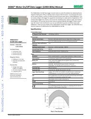
Function Comparison of <strong>Acuvim</strong> II series Meters<br />
METERING<br />
TOU<br />
CATEGORY ITEM Parameters<br />
REAL TIME<br />
METERING<br />
ENERGY &<br />
DEMAND<br />
Phase Voltage<br />
Line Voltage<br />
Current<br />
Power<br />
Reactive Power<br />
Apparent Power<br />
Power Factor<br />
Frequency<br />
Load Features<br />
V1, V2, V3, Vlnavg<br />
V12, V23, V31, Vllavg<br />
I1, I2, I3, In, Iavg<br />
P1, P2, P3, Psum<br />
Q1, Q2, Q3, Qsum<br />
S1, S2, S3, Ssum<br />
PF1, PF2, PF3, PF<br />
F<br />
Load Features<br />
Four Quadrant PowersFour Quadrant Powers<br />
Energy<br />
Reactive Energy<br />
Apparent Energy<br />
Demand<br />
TIME OF USE Energy/max demand<br />
DAYLIGHT SAVING<br />
Two formats adjust<br />
TIME<br />
voltage and current<br />
Waveform Capture<br />
Waveform<br />
Ep_imp, Ep_exp, Ep_total, Ep_net<br />
Eq_imp, Eq_exp, Eq_total, Eq_net<br />
Es<br />
Dmd_P, Dmd_Q, Dmd_S, Dmd_I1,<br />
Dmd_I2, Dmd_I3<br />
TOU, 4 Tariffs, 12 Seasons, 14<br />
Schedules<br />
Month/Day/Hour/Minute; Month/<br />
Week/First few weeks/Hour/Minute<br />
Trigger, <strong>Manual</strong>, DI change, Sag/<br />
Dips, Swell, Over Current<br />
Voltage Unbalance<br />
Factor<br />
U_unbl<br />
Current Unbalance<br />
Factor<br />
I_unbl<br />
Voltage THD THD_V1,THD_V2,THD_V3, THD_Vavg<br />
MONITORING<br />
POWER QUALITY Current THD THD_I1, THD_I2, THD_I, THD_Iavg<br />
Harmonics 2nd to 31 st ( 63 rd for<br />
Individual Harmonics<br />
<strong>Acuvim</strong> IIR,/llE/llW)<br />
Voltage Crest Factor Crest Factor<br />
TIF<br />
THFF<br />
Current K factor K Factor<br />
STATISTICS<br />
Each phase of V & l;Total of P, Q, S,<br />
MAX with Time Stamp<br />
PF & F;Demad of P,Q & S;Each phase<br />
MIN with Time Stamp<br />
THD of V & I;Unbalnce factor of V & I<br />
<strong>Acuvim</strong><br />
II<br />
<strong>Acuvim</strong><br />
IIR<br />
<strong>Acuvim</strong> <strong>Acuvim</strong><br />
IIE IIW
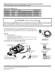
ALARM<br />
Over/Under Limit<br />
Alarm<br />
V,I,P,Q,S,PF,V_THD & I_THD each<br />
phase and total or average;<br />
Unbalance factor of V & I;load<br />
type;Analog Input of each channel<br />
POWER QUALITY<br />
EVENT LOGGING<br />
SAG/DIPS,SWELL Voltage<br />
OTHERS<br />
OPTION<br />
MODULE<br />
Data Logging<br />
Data Logging 1<br />
Data Logging 2<br />
Data Logging 3<br />
F, V1/2/3/lnavg, V12/23/13/lavg,<br />
I1/2/3/n/avg, P1/2/3/sum, Q1/2/3/<br />
sum, S1/2/3/sum, PF1/2/3, PF, U_<br />
unbl, I_unbl, Load Type, Ep_imp,<br />
Ep_exp, Ep_total, Ep_net, Eq_<br />
imp, Eq_exp, Eq_total, Eq_net, Es,<br />
THD_V1/2/3/avg, THD_I1/2/3/avg,<br />
Harmonics 2 nd to 63 rd , Crest Factor,<br />
THFF, K Factor, sequence and phase<br />
angles, DI counter, AI, AO, Dmd P/Q/<br />
S, Dmd I1/2/3<br />
ONBOARD<br />
MEMORY SIZE<br />
Memory Bytes — 4MB 4MB 8MB<br />
RS485 Port,Half<br />
COMMUNICATION Duplex,<br />
Modbus®-RTU Protocol<br />
Optical Isolated<br />
TIME Real Time Clock<br />
Year, Month, Date, Hour, Minute,<br />
Second<br />
Switch Status (DI) Digital Input (Wet)<br />
Power Supply for DI 24 Vdc<br />
Relay Output (RO) NO, Form A<br />
I/O OPTION Digital Output (DO) Photo-MOS<br />
Pulse Output (PO) By using DO<br />
Analog Input (AI) 0(4)~20mA, 0(1)~5V<br />
Analog Output (AO) 0(4)~20mA, 0(1)~5V<br />
Ethernet<br />
10M/100M, Modbus-TCP, HTTP<br />
Webpage, Email<br />
COMMUNICATION<br />
Profibus-DP<br />
Profibus-DP/V0<br />
RS485 Module Additional Modbus RTU<br />
Function; Option; Blank NA
Chapter 2 Installation<br />
2.1 Appearance and Dimensions<br />
2.2 Installation Methods<br />
2.3 Wiring<br />
2.3.1 Terminal Strips<br />
2.3.2 Power Requirements<br />
2.3.3 Voltage Input Wiring<br />
2.3.4 Current Input Wiring<br />
2.3.5 Frequently Used Wiring Methods<br />
2.3.6 Communication
Considerations When Installing Meters<br />
10<br />
• Installation of the meter must be performed by qualified personnel only, who<br />
follow standard safety precautions through the installation procedures. Those<br />
personnel should have appropriate training and experience with high voltage<br />
devices. Appropriate safety gloves, safety glasses and protective clothing are<br />
re<strong>com</strong>mended.<br />
• During normal operation, dangerous voltage may flow through many parts of<br />
the meter, including terminals, and any connected CTs (Current Transformers)<br />
and PTs (Potential Transformers), all I/O (Inputs and Outputs) modules and their<br />
circuits. All primary and secondary circuits can, at times, produce lethal voltages<br />
and currents. AVOID contact with any current-carrying surfaces.<br />
• The meter and its I/O output channels are NOT designed as primary protection<br />
devices and shall NOT be used as primary circuit protection or in an energylimiting<br />
capacity. The meter and its I/O output channels can only be used as<br />
secondary protection. AVOID using the meter under situations where failure of<br />
the meter may cause injury or death. AVOID using the meter for any application<br />
where risk of fire may occur.<br />
• All meter terminals should be inaccessible after installation.<br />
• Do NOT perform Dielectric (HIPOT) test to any inputs, outputs or<br />
<strong>com</strong>munication terminals. High voltage testing may damage electronic<br />
<strong>com</strong>ponents of the meter.<br />
• Applying more than the maximum voltage the meter and/or its modules can<br />
withstand will permanently damage the meter and/or its modules. Please refer<br />
to the specifications for all devices before applying voltages.
• When removing meter for service, use shorting blocks and fuses for voltage<br />
leads and power supply to prevent hazardous voltage conditions or damage<br />
to CTs. CT grounding is optional.<br />
• ACCUENERGY re<strong>com</strong>mends using a dry cloth to wipe the meter.<br />
NOTE: IF THE EQUIPMENT IS USED IN A MANNER NOT SPECIFIED<br />
BY THE MANUFACTURER, THE PROTECTION PROVIDED BY THE<br />
EQUIPMENT MAY BE IMPAIRED.<br />
NOTE: THERE IS NO REQUIRED PREVENTIVE MAINTENANCE OR<br />
INSPECTION NECESSARY FOR SAFETY. HOWEVER, ANY REPAIR OR<br />
MAINTENANCE SHOULD BE PERFORMED BY THE FACTORY.<br />
DISCONNECT DEVICE: The following part is considered the equipment<br />
disconnect device.<br />
A SWITCH OR CIRCUIT-BREAKER SHALL BE INCLUDED IN THE INSTALLATION.<br />
THE SWITCH SHALL BE IN CLOSE PROXIMITY TO THE EQUIPMENT AND WITHIN<br />
EASY REACH OF THE OPERATOR. THE SWITCH SHALL BE MARKED AS THE<br />
DISCONNECTING DEVICE FOR THE EQUIPMENT.<br />
11
The installation method is introduced in this chapter. Please read this chapter<br />
carefully before beginning installation.<br />
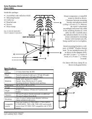
2.1 Appearance and Dimensions<br />
Unit: mm(inches)<br />
Multifunction Power Meter<br />
<br />
96.00 (3.800)<br />
<br />
Gasket<br />
96.00 (3.800)<br />
H P E V/A<br />
<br />
96.00 (3.800)<br />
Front View of the Display Meter<br />
and Remote Display Unit<br />
Gasket<br />
7.60 (0.300)<br />
<br />
91.00 (3.583)<br />
<br />
91.00 (3.583)<br />
91.00 (3.583)<br />
38.00 (1.496)<br />
35.90<br />
(1.413)<br />
50.70 (1.996) 12.8<br />
(0.504)<br />
Side View of the<br />
Display Meter<br />
35.90<br />
(1.413)<br />
12.8<br />
(0.504)<br />
Side View of the<br />
Remote Display Unit<br />
35.90<br />
(1.413)<br />
50.70 (1.996)<br />
14.00<br />
(0.551)<br />
Side View of the<br />
DIN rail Meter<br />
12
96.00 (3.800)<br />
Fig 2-1 Appearance and dimensions of <strong>Acuvim</strong> II series meter<br />
LCD Display<br />
Front Casing<br />
Key<br />
Enclosure<br />
Part Name<br />
DIN rail<br />
Voltage Input Terminals<br />
Current Input Terminals<br />
Power Supply Terminals<br />
Communication Terminals<br />
Interface<br />
Installation Clip<br />
Gasket<br />
Table 2-1 Part name of <strong>Acuvim</strong> II series meter<br />
Description<br />
Large bright white backlight LCD display.<br />
Visible portion (for display and control) after mounting<br />
onto a panel.<br />
Four keys are used to select display and set.<br />
The <strong>Acuvim</strong> II series meter enclosures is made of high<br />
strength anti-<strong>com</strong>bustible engineering plastic.<br />
Used for Installation 35mm rail of the DIN rail Meter.<br />
Used for voltage input.<br />
Used for current input.<br />
Used for control power input<br />
Communication output.<br />
Used for link the remote display unit and the DIN rail<br />
meter.<br />
Used for fixing the meter to the panel.<br />
Insert the gasket in between the meter and the cutout to<br />
cover up gaps from the round hole.<br />
13
2.2 Installation Methods<br />
Environmental<br />
Before installation, please check the environment, temperature and humidity to<br />
ensure the <strong>Acuvim</strong> II series meter is being placed where optimum performance<br />
will occur.<br />
Temperature<br />
Operation: -25˚C to 70˚C.<br />
Storage: -40˚C to 85˚C<br />
Humidity<br />
5% to 95% non-condensing.<br />
The <strong>Acuvim</strong> II series meter should be installed in a dry and dust free<br />
environment. Avoid exposing meter to excessive heat, radiation and high<br />
electrical noise source.<br />
Installation Steps<br />
The <strong>Acuvim</strong> II series meter can be installed into a standard ANSI C39.1 (4”<br />
Round) or an IEC 92mm DIN (Square) form.<br />
1. Cut a square hole or round hole on the panel of the switch gear.<br />
The cutting size is shown in fig 2.3.<br />
Unit: mm (inches)<br />
14<br />
Fig 2-2 Panel Cutout
2. Remove the clips from the meter, and insert the meter into the square hole<br />
from the front side. Please note: optional rubber gasket must be installed on<br />
the meter before inserting the meter into the cut out.<br />
Panel<br />
Panel<br />
Fig 2-3 Put the meter into the opening<br />
3. Install clips on the back side of the meter and secure tightly to ensure the<br />
meter is affixed to the panel.<br />
Panel<br />
Fig 2-4 Use the clips to fix the meter on the panel<br />
Note: The display meter and the remote display unit have the same installation<br />
method. The DIN rail meter is simply installed on a 35mm DIN rail.<br />
15
2.3 Wiring<br />
2.3.1 Terminal Strips<br />
There are four terminal strips at the back of the <strong>Acuvim</strong> II series meter. The three<br />
phase voltage and current are represented by using 1, 2, and 3 respectively.<br />
These numbers have the same meaning as A, B, and C or R, S, and T used in<br />
other literature.<br />
Current Input Terminal Strip<br />
Voltage Input Terminal Strip<br />
Power Supply Terminal Strip<br />
Communication Terminal Strip<br />
Fig 2-5 Terminal Strips of <strong>Acuvim</strong> II series meter<br />
16
DANGER<br />
Only the qualified<br />
personnel does do<br />
the wire connection<br />
work. Make sure the<br />
power supply is cut off<br />
and all the wires are<br />
powerless. Failure to<br />
observe it may result in<br />
severe injury or death.<br />
Safety Earth Connection<br />
Before setting up the meter's wiring, please make sure<br />
that the switch gear has an earth ground terminal.<br />
Connect both the meter's and the switch gear's<br />
ground terminal together. The following ground<br />
terminal symbol is used in this user's manual.<br />
NOTE<br />
Make sure the control<br />
power terminal of<br />
the meter ground is<br />
connected to the safety<br />
Earth of switchgear.<br />
NOTE<br />
Make sure the voltage<br />
of power supply is<br />
the same as what the<br />
meter needed for its<br />
control power.<br />
Fig 2-6 Safety Earth Symbol<br />
2.3.2 Power Requirement<br />
Control Power<br />
There are 2 options for the Control Power of the<br />
<strong>Acuvim</strong> II series meter:<br />
1. Standard: 100~415Vac (50/60Hz) or 100-300Vdc<br />
2. Low Voltage DC Option: 20-60Vdc<br />
The 2 options must be chosen according to the<br />
application. Please see the ordering information<br />
appendix for further details.<br />
The meter's typical power consumption is very low<br />
and can be supplied by an independent source<br />
or by the measured load line. A regulator or an<br />
uninterrupted power supply (UPS) should be used<br />
under high power fluctuation conditions. Terminals<br />
for the control power supply are 11, 12 and 13 (L,<br />
N, and Ground). A switch or circuit-breaker shall be<br />
included in a building installation. It shall be in close<br />
17
proximity to the equipment, within easy reach of the operator, and shall be<br />
marked as the disconnecting device for the equipment.<br />
Fig 2-7 Power supply<br />
A fuse (typical 1A/250Vac) should be used in the auxillary power supply loop.<br />
No. 13 terminal must be connected to the ground terminal of the switchgear.<br />
An isolated transformer or EMC filter should be used in the control power supply<br />
loop if there is a power quality problem in the power supply.<br />
NOTE<br />
A filter should be<br />
used if there is<br />
an EMI problem.<br />
Fig 2-8 Power supply With EMC filter<br />
Choice of wire of power supply is AWG22-16 or 0.6-1.5mm 2 .<br />
Voltage Input<br />
Maximum input voltage for the <strong>Acuvim</strong> II series meter shall not exceed<br />
400LN/690LL VAC rms for three phase or 400LN VAC rms for single phase.<br />
Potential Transformer (PT) must be used for high voltage systems. Typical<br />
secondary output for PTs shall be 100V or 120V. Please make sure to select an<br />
18
appropriate PT to maintain the measurement accuracy of the meter. When<br />
connecting using the star configuration wiring method, the PT's primary side<br />
rated voltage should be equal to or close to the phase voltage of the system to<br />
utilize the full range of the PT. When connecting using the delta configuration<br />
wiring method, the PT's primary side rated voltage should be equal to or close<br />
to the line voltage of the system. A fuse (typical 1A/250Vac) should be used in<br />
the voltage input loop. The wire for voltage input is AWG16-12 or 1.3-2.0mm 2 .<br />
Note: In no circumstance should the secondary of the PT be shorted. The<br />
secondary of the PT should be grounded at one end. Please refer to the wiring<br />
diagram section for further details.<br />
Current Input<br />
Current Transformers (CTs) are required in most engineering applications.<br />
Typical current rating for the secondary side of the CT shall be 5A (standard)<br />
or 1A (Optional), please refer to the ordering information appendix for further<br />
details. CTs must be used if the system rated current is over 5A. The accuracy<br />
of the CT should be better than 0.5% with rating over 3VA is re<strong>com</strong>mended in<br />
order to preserve the meter's accuracy. The wire between CTs and the meter<br />
shall be as short as possible. The length of the wire have an effect on the<br />
accuracy.<br />
The wire size of current input is AWG15-10 or 1.5-2.5mm 2 .<br />
Note: The secondary side of the CT should not be open circuit in any<br />
circumstance when the power is on. There should not be any fuse or switch in<br />
the CT loop. One end of the CT loop should be connected to the ground.<br />
Vn Connection<br />
Vn is the reference point of the <strong>Acuvim</strong> II series meter voltage input. Low wire<br />
resistance helps improve the measurement accuracy. Different system wiring<br />
19
modes require different Vn connection methods. Please refer to the wiring<br />
diagram section for more details.<br />
Three Phase Wiring Diagram<br />
This meter can satisfy almost any kind of three phase wiring diagrams. Please<br />
read this section carefully before choosing the suitable wiring method for your<br />
power system.<br />
Voltage and current input wiring mode can be set separately in the meter<br />
parameter setting process. The voltage wiring mode can be set as 3-phase 4-line<br />
Wye (3LN), 3-phase 4-line 2PT Wye mode (2LN*) and 3-phase 3-line open delta<br />
(2LL). The current input wiring mode can be set as 3CT, 2CT and 1CT*. Any<br />
voltage mode can be grouped with one of the current modes.<br />
Note: " * " wiring method not applicable to <strong>Acuvim</strong> IIR/IIE/IIW.<br />
2.3.3 Voltage Input Wiring<br />
3-Phase 4-Line Wye Mode (3LN)<br />
The 3-Phase 4-Line wye mode is <strong>com</strong>monly used in low voltage electric<br />
distribution power systems. For voltage lower than 400LN/690LL Vac, power<br />
line can be connected directly to the meter's voltage input terminal as shown in<br />
fig 2.10a. For high voltage systems (over 400LN/690LL Vac), PTs are required as<br />
shown in fig 2.10b. The meter should be set to 3LN for both voltage levels.<br />
20
Fig 2-9a 3LN direct connection<br />
Fig 2-9b 3LN with 3PT<br />
3-Phase 4-Line 2PT Mode (2LN*)<br />
In a 3-Phase 4-Line wye system, 2PT wye mode is used when the 3 phase power<br />
system is balanced. The connection method is shown in fig 2.11. The voltage<br />
of V2 is calculated according to the V1 and V3. The voltage input mode of the<br />
meter should be set to 2LN for the 2PT voltage input wiring mode.<br />
21
Fig 2-10 2LN with 2PTs (*)<br />
3-Phase 3-Line Direct Connection Mode (3LL)<br />
In a 3-Phase 3-Line system, power line A, B and C are connected to V1, V2 and<br />
V3 directly. Vn is floated. The voltage input mode of the meter should be set to<br />
3LL.<br />
Fig 2-11 3LN 3-Phase 3-Line direct connection<br />
3-Phase 3-Line open Delta Mode (2LL)<br />
Open delta wiring mode is often used in high voltage systems. V2 and Vn are<br />
22
connected together in this mode. The voltage input mode of the meter should<br />
be set to 2LL for this voltage input wiring mode.<br />
Fig 2-12 2LL with 2PTs<br />
2.3.4 Current Input Wiring<br />
3CT<br />
The 3CT current wiring configuration can be used when either 3CTs are<br />
connected (as shown in Fig 2.14) or 2CTs are connected (as shown in Fig 2.15)<br />
to the system. In either case, there is current flowing through all three current<br />
terminals.<br />
Fig 2-13 3CTs a<br />
23
Fig 2-14 3CTs b<br />
2CT<br />
The difference between Fig 2.15 and Fig 2.16 is that no current flows through<br />
current input terminal I21 and I22. The meter should be set to the I2 value<br />
which is calculated from formula i1+i2+i3=0. The current input mode of the<br />
meter should be set to 2CT .<br />
Fig 2-15 2CTs<br />
1CT*<br />
If it is a three phase balanced system, 1 CT connection method can be used. The<br />
other two channels are calculated accordingly.<br />
24
Fig 2-16 1CT (*)<br />
2.3.5 Frequently Used Wiring Method<br />
In this section, the most <strong>com</strong>mon voltage and current wiring <strong>com</strong>binations<br />
are shown in different diagrams. In order to display measurement readings<br />
correctly, please select the appropriate wiring diagram according your setup<br />
and application.<br />
1. 3LN, 3CT with 3 CTs.<br />
Fig 2-17 3LN, 3CT<br />
25
2. 3LN, 3CT with 2 CTs<br />
3. 2LN, 2CT*<br />
Fig 2-18 3LN, 3CT with 2CTs<br />
Fig 2-19 2LN, 2CT (*)<br />
26
4. 2LN, 1CT*<br />
5. 2LL, 3CT<br />
Fig 2-20 2LN, 1CT (*)<br />
Fig 2-21 2LL, 3CT<br />
27
6. 2LL, 2CT<br />
7. 2LL, 1CT*<br />
Fig 2-22 2LL, 2CT<br />
Fig 2-23 2LL, 1CT (*)<br />
28
8. Single Phase 2 Line (Wiring mode setting 3LN, 3CT)<br />
Fig 2-24 Single phase 2Lines<br />
9. Single Phase 3 Line (Wiring mode setting 3LN, 3CT)<br />
Fig 2-25 Single phase 3Lines<br />
29
2.3.6 Communication<br />
<strong>Acuvim</strong> II series meter uses RS485 serial <strong>com</strong>munication and the Modbus-<br />
RTU protocol. The terminals of <strong>com</strong>munication are A, B, and S (14, 15, 16). A is<br />
differential signal +, B is differential signal - and S is connected to the shield of<br />
the twisted pair cables. Up to 32 devices can be connnected on a RS485 bus.<br />
Use good quality shielded twisted pair cable, AWG22 (0.5mm 2 ) or higher. The<br />
overall length of the RS485 cable connecting all devices should not exceed<br />
1200m (4000ft). The <strong>Acuvim</strong> II series meter is used as a slave device of masters<br />
such as a PC, PLC, Data Collector or RTU.<br />
If the master does not have RS485 <strong>com</strong>munication port, a converter (such as a<br />
RS232/RS485 or a USB/RS485 converter) will be required. Typical RS485 network<br />
topologies include line, circle and star (wye).The shield of each segment of the<br />
RS485 cable must be connected to the ground at one end only.<br />
Every A(+) should be connected to A(+), B(-) to B(-), or it will influence the<br />
network, or even damage the <strong>com</strong>munication interface.<br />
The connection topology should avoid “T” type which means there is a new<br />
branch and it does not begin from the beginning point.<br />
Keep <strong>com</strong>munication cables away from sources of electrical noise whenever<br />
possible.<br />
When using a long <strong>com</strong>munication cable to connect several devices, an anti<br />
signal reflecting resistor (typical value 120Ω-300Ω/0.25W) is normally added<br />
to the end of the cable beside the last meter if the <strong>com</strong>munication quality is<br />
distorted.<br />
Use RS232/RS485 or USB/RS485 converter with optical isolated output and<br />
surge protection.<br />
30
Chapter 3 Meter Display and Parameter Settings<br />
3.1 Display Panel and Keys<br />
3.2 Metering Data<br />
3.3 Statistics Data<br />
3.4 Demand Data<br />
3.5 Harmonic Data<br />
3.6 Expanded I/O Module Data<br />
3.7 Parameter Settings Mode<br />
3.8 Page Recovery Function
Detailed human-machine interface of the meter will be described in this<br />
chapter. This includes viewing real-time metering data and setting parameters<br />
using different key <strong>com</strong>bination.<br />
3.1 Display Panel and Keys<br />
The front of the <strong>Acuvim</strong> II series meter consists of an LCD screen and four control<br />
keys. All the display segments are illustrated in fig 3.1. <strong>User</strong>s should note that<br />
all the segments will not display in a single page under normal conditions.<br />
1<br />
4<br />
10<br />
5<br />
2<br />
6<br />
7<br />
8<br />
9<br />
11<br />
12<br />
3<br />
17<br />
13 14 15 16<br />
Fig 3-1 All Display Segments<br />
32
SN Display Description<br />
1 Display mode indication<br />
Shows different modes on the display area. “Meter”<br />
for real-time measurement; “Max/Min” for statistic<br />
data; “Demand” for power demand data; “Harmonic”<br />
for harmonic data; “Setting” for parameters setting;<br />
“Digital I/O” for expanded IO module data.<br />
Main display area: displays metering data such as<br />
2<br />
voltage, current, power, power factor, frequency,<br />
Four lines of “ ” digits in the<br />
unbalance, phase angle,etc. Displays statistics such<br />
metering area<br />
as maximum and minimum, demand data, display<br />
settings and expanded I/O data.<br />
3 Four “ ” and five “ ” digits<br />
4 Three “ ” digits<br />
5 Unbalance, THD, TDD, MAX, MIN<br />
6 Load rate<br />
Displays energy data and real-time clock. Also used<br />
for the setting mode and digital I/O mode display.<br />
Item Icons: “U” for voltage; “I” for current; “P” for active<br />
power; “Q” for reactive power; “S” for apparent power;<br />
“PF” for power factor; “F” for frequency; “ ” for phase<br />
angles; “DMD” for demand; "Mxx" for expanded IO<br />
module type; and display setting page number.<br />
Item Icons: “Unbalance” for unbalance of the voltage<br />
and current; “THD” for total harmonics distortion;<br />
“TDD” for total demand distortion; “MAX” for<br />
maximum and “MIN” for minimum<br />
Displays the percentage of load current to the<br />
nominal current.<br />
7<br />
Four quadrant icon<br />
Load type icon<br />
: quadrant of the system power<br />
: inductive load; : capacitive load<br />
8 1-2, 2-3, 3-1, avg, N<br />
9 Energy icon: Imp, Total, Net, Exp<br />
1, 2, 3 for 3 phase A, B, C; 1-2, 2-3, 3-1 for 3 phase lineto-line<br />
AB, BC, CA; avg for average and N for neutral.<br />
Imp: import energy<br />
Exp: export energy<br />
Total: absolute sum of Imp and Exp energy<br />
Net: algebraic sum of Imp and Exp energy<br />
33
10 Units measured<br />
11 Communication icon<br />
12 Energy pulse output indicator<br />
13<br />
Expanded I/O module<br />
indicator<br />
voltage: V, kV; current: A, kA:active power: kW, MW;<br />
reactive power: kvar, Mvar; apparent power: kVA, MVA;<br />
frequency: Hz; active energy: kWh; reactive energy:<br />
kvarh; apparent energy: kVAh; percentage: %; phase<br />
angle: °<br />
No icon: no <strong>com</strong>munication<br />
One icon: query sent<br />
Two icons: query sent and response received<br />
No icon: no pulse output<br />
With icon: icon blinks when sending pulse output<br />
M1: one AXM-IO1 connected<br />
M1x2: two AXM-IO1 connected<br />
None: no AXM-IO1 connected<br />
M2: one AXM-IO2 connected<br />
M2x2: two AXM-IO2 connected<br />
None: no AXM-IO2 connected<br />
M3: one AXM-IO3 connected<br />
M3x2: two AXM-IO3 connected<br />
None: no AXM-IO3 connected<br />
14<br />
15<br />
Profibus module indicator<br />
Ethernet module indicator<br />
No icon: Profibus module not connected<br />
With icon: Profibus module connected<br />
No icon: Ethernet module not connected<br />
With icon: Ethernet module connected<br />
16 Current tariff<br />
17 Time icon Time display<br />
There are four keys on the front panel, labeled H, P, E and V/A from left to<br />
right. Use these four keys to read real-time metering data, set parameters and<br />
navigate the meter.<br />
Note: If the LCD backlight is off, pressing any key one time will bring the<br />
backlight on.<br />
34
3.2 Metering Data<br />
Pressing H and V/A simultaneously will activate the display mode selection and<br />
the cursor will flash. Press P or E to move the cursor right or left. To enter the<br />
metering mode, move the cursor to "Meter" then press V/A.<br />
In the metering mode, press P and E simultaneously will enter the TOU mode.<br />
In metering mode, the meter displays measurements such as voltage, current,<br />
power, power factor, phase angle, unbalance etc.<br />
In the TOU mode, meter displays the energy, maximum demand and it's time in<br />
different tariffs.<br />
a) Voltage and Current:<br />
Press V/A to read voltage and current in the metering area. The screen will roll<br />
to the next page when V/A is pressed again. It will go back to the first screen if<br />
you press V/A at the last screen.<br />
The following figure shows the sequence:<br />
35
Note: When the meter is set to “2LL” or “3LL”, there is no phase voltage or neutral<br />
current display. Therefore, only the third screen (line voltage & avg) and the the<br />
fourth screen (three phase current & avg) will be displayed.<br />
b) Power, Power Factor and Frequency:<br />
Press P to display power related data.<br />
The screen will roll to the next page when P is pressed again. It will go back to<br />
the first screen if you press P at the last screen.<br />
The following figure shows the sequence:<br />
Note: When the meter is set to “2LL” or “3LL”, only the fifth screen (system power)<br />
and the sixth screen (system power factor & frequency) will be displayed.<br />
36
c) Phase Angles and Unbalance:<br />
Press H to display phase angles and unbalance data. The screen will roll to the<br />
next page when H is pressed again. It will go back to the first screen if you press<br />
H at the last screen.<br />
The following figure shows the sequence:<br />
When using "2LL" or "3LL" wiring setting mode, voltage stands for line to line<br />
voltage. Otherwise, voltage stands for line-to-neutral voltage.<br />
d) Energy:<br />
Press E key to display energy and real time clock. The screen will roll to the next<br />
page when E is pressed again. It will go back to the first screen if you press E at<br />
the last screen.<br />
<strong>Acuvim</strong> II series meter can be set to record primary energy or secondary<br />
energy.The unit of energy is kWh for active energy, kvarh for reactive energy<br />
and kVAh for apparent energy. The running time has a resolution of 0.01h.<br />
The meter begins accumulating time upon initial powering up of the unit. The<br />
accumulated time is stored in the non-volatile memory. It can be reset via<br />
37
<strong>com</strong>munication or from the meter front.<br />
The following figure shows the sequence:<br />
e) TOU display<br />
Press “P” and “E” simultaneously to enter the TOU Energy and maximum demand<br />
page. Press “E”display the TOU energy. Press “P”display the TOU maximum<br />
demand. Press again display the TOU maximum demand year,month and date.<br />
Press again display the TOU maximum demand hour, minute and second. Press<br />
“H”would change the tariffs page. It displays energy under different tariffs in<br />
the energy page. It also displays demand under different tariffs in the maximum<br />
demang page. Press “V/A”would display different type energy and maximum<br />
demand. Press “P” and“E” simultaneously to exit current page and return to<br />
metering mode.<br />
38
Sharp Import energy<br />
P<br />
Sharp Import max demand<br />
P<br />
Sharp Import max demand year/month/day<br />
V/A<br />
Sharp Export energy<br />
V/A<br />
Sharp import reactive energy<br />
V/A<br />
Sharp Export reactive energy<br />
V/A<br />
Sharp Apparent energy<br />
V/A<br />
Peak Import energy<br />
V/A<br />
……….<br />
V/A<br />
Peak Apparent energy<br />
V/A<br />
………<br />
V/A<br />
Valley Apparent energy<br />
V/A<br />
………<br />
V/A<br />
Normal Apparent energy<br />
V/A<br />
………<br />
V/A<br />
Total Apparent energy<br />
E<br />
P<br />
E<br />
P<br />
E<br />
P<br />
E<br />
P<br />
E<br />
P<br />
E<br />
P<br />
E<br />
P<br />
E<br />
P<br />
E<br />
P<br />
E<br />
P<br />
E<br />
P<br />
E<br />
P<br />
E<br />
P<br />
E<br />
V/A<br />
Sharp Export max demand<br />
V/A<br />
Sharp import reactive max demand<br />
V/A<br />
Sharp Export reactive max demand<br />
V/A<br />
Sharp Apparent max demand<br />
V/A<br />
Peak Import max demand<br />
V/A<br />
……….<br />
V/A<br />
Peak A pparent max demand<br />
V/A<br />
………<br />
V/A<br />
Valley Apparent max demand<br />
V/A<br />
………<br />
V/A<br />
Normal Apparent max demand<br />
V/A<br />
………<br />
V/A<br />
Total Apparent max demand<br />
P<br />
P<br />
P<br />
P<br />
P<br />
P<br />
P<br />
P<br />
P<br />
P<br />
P<br />
P<br />
P<br />
P<br />
Sharp Import max demand hour/min/sec<br />
……….<br />
……….<br />
……….<br />
……….<br />
……….<br />
……….<br />
……….<br />
……….<br />
……….<br />
……….<br />
……….<br />
……….<br />
39
3.3 Statistics Data<br />
Pressing H and V/A simultaneously will activate the display mode selection and the cursor will<br />
flash. Press P or E to move the cursor right or left. To enter the statistics data mode, scroll the<br />
cursor to "Max/Min" then press V/A.<br />
In statistics data mode, the meter displays the maximum values and minimum values<br />
for voltage, current, power, power factor, unbalance, demand, THD etc. <strong>User</strong> should<br />
note that time stamp for the parameters can be viewed only from the software through<br />
<strong>com</strong>munication. No <strong>com</strong>mands are associated with the key H in "Max/Min" display mode.<br />
When P is pressed again, the screen will roll to the next page, and will roll back to the first<br />
screen when pressed at the last page.<br />
When E is pressed the screen will roll back to the previous page, and will roll back to the last<br />
screen when pressed at the first page.<br />
Press V/A to switch the view between maximum and minimum. For example, if the current<br />
display is the maximum phase voltage value, when V/A is pressed, the display<br />
will show the minimum phase voltage value. If V/A is pressed again, the display<br />
will switch back to show the maximum phase voltage value.<br />
The following figure shows the sequence:<br />
40
Note:<br />
i) The figure shows the rolling sequence when pressing P. The sequence will be<br />
reversed when pressing E.<br />
ii) When the meter is set to “2LL” or “3LL”, the first screen(max value of phase<br />
voltage) will not be displayed.<br />
3.4 Demand Data<br />
Pressing H and V/A simultaneously will activate the display mode selection<br />
and the cursor will flash. Press P or E to move the cursor right or left. To enter<br />
demand mode, move the cursor to "Demand" then press V/A.<br />
In the demand data mode, the first screen displays the demand of active power,<br />
reactive power and apparent power, and the second screen displays the current<br />
demand of phase A, phase B and phase C.<br />
As shown in the figure, system active power demand is 3.285kW, system reactive<br />
power demand is 0 kvar, system apparent power demand is 3.285 kVA.<br />
41
3.5 Harmonic Data<br />
Pressing H and V/A simultaneously will activate the display mode selection<br />
and the cursor will flash. Press P or E to move the cursor right or left. To enter<br />
harmonic mode, move the cursor to "Harmonic" then press V/A.<br />
In the harmonic data mode, meter displays the harmonic ratio of voltage and<br />
current, THD, odd HD, even HD, THFF, CF and KF.<br />
a) Power Quality Data:<br />
Press H to display power quality data. When H is pressed again, the screen will<br />
roll to the next page and will roll back to the first screen when pressed at the<br />
last page.<br />
No <strong>com</strong>mands are associated with keys P and E in "Harmonic" display mode.<br />
Press V/A to switch to harmonic ratio data display.<br />
42
) Harmonic Ratio Data<br />
Press H to switch to power quality data display.<br />
The harmonic order will increase by one each time P is pressed and will return<br />
to the 2 nd when P is pressed at the 31 st (63 rd for <strong>Acuvim</strong> IIR/IIE/IIW ) harmonic.<br />
The harmonic order will decrease by one each time E is pressed and will return<br />
to the 31 st (63 rd for <strong>Acuvim</strong> IIR/IIE/IIW) when E is pressed at the 2 nd harmonic.<br />
Press V/A to switch display between voltage harmonics and current harmonics.<br />
The following figure shows the sequence:<br />
43
Note: The figure shows the rolling sequence when pressing P. If E is pressed,<br />
the sequence will reverse.<br />
3.6 Expanded I/O Module Data<br />
Pressing H and V/A simultaneously will activate the display mode selection and<br />
the cursor will flash. Press P or E to move the cursor right or left. To access data<br />
from the expanded I/O modules, move the cursor to "Digital I/O" then press V/A<br />
to enter the expanded I/O module data mode.<br />
In the expanded I/O module data mode, the meter displays the data from<br />
expanded I/O modules, such as DI status, pulse counter number, relay status,<br />
analog input, and analog output etc.<br />
In this mode, the first page is module selection. You can choose to view the<br />
available modules that are attached to the meter. If no expanded I/O modules<br />
are connected, the screen will display "NO IO".<br />
44
a) Module Selection:<br />
No <strong>com</strong>mands are associated with the key H in the module selection screen.<br />
Press P to move the cursor downwards, the cursor will move to the top when it<br />
reaches the bottom. If only one module is connected, Pressing P will have no<br />
effect.<br />
Press E to move the cursor upwards, the cursor will move to the bottom when it<br />
reaches the top. If only one module is connected, Pressing E will have no effect.<br />
Press V/A to select the module and enter the I/O module data selection mode.<br />
As shown in the figure, three modules are connected, AXM-IO11, AXM-IO21,<br />
AXM-IO31, which are indicated by M11, M21, M31 respectively. The cursor<br />
points to M21, which indicates that AXM-IO21 is chosen now.<br />
b) I/O Module Data Selection<br />
Press H to return to module selection screen.<br />
Press P to move the cursor downwards, the cursor will move to the top when<br />
it reaches the bottom. Please note that there are 3 parameters for AXM-IO1, 3<br />
parameters for AXM-IO2 and 4 parameters for AXM-IO3.<br />
45
Press E to move the cursor upwards, the cursor will move to the bottom when it<br />
reaches the top.<br />
Press V/A to select the parameter and enter the display of the data.<br />
c) I/O module data display<br />
Press H to return to I/O module data selection screen.<br />
The screen will roll to the next page each time P is pressed and will return to the<br />
first page when P is pressed at the last page. If only one page exists, pressing P<br />
will have no effect.<br />
The screen will roll to the last page each time E is pressed and will return to the<br />
last page E is pressed at the first page. If only one page exists, pressing E will<br />
have no effect.<br />
No <strong>com</strong>mands are associated with the key V/A in this display.<br />
The following figure shows the sequence:<br />
46
48<br />
Note: The figure shows the rolling sequence for using key P. If using E key for<br />
rolling page, the sequence will reverse.<br />
3.7 Parameter Setting Mode<br />
Pressing H and V/A simultaneously will activate the display mode selection<br />
and the cursor will flash. Press P or E to move the cursor right or left. To enter<br />
parameter setting mode, move the cursor to "Setting" then press V/A.<br />
In the parameter setting mode, parameters such as system parameters,<br />
expanded I/O module parameters, alarm parameters and Ethernet module<br />
parameters, can be read and modified.<br />
a) Password Inquiry:<br />
Parameter setting mode is password protected. Before entering the<br />
password and getting into the parameter setting mode, the meter's device
<strong>com</strong>munication address will display for 3 seconds. A four digit password (0000<br />
to 9999) is required everytime before accessing the parameter setting mode.<br />
The default password is 0000. After entering the password, press V/A to go to<br />
the parameter selection page. The meter will return to the metering mode if a<br />
wrong password is entered.<br />
The following figure shows the password inquiry page.<br />
To input password:<br />
Press H to move the flashing cursor to the next position.<br />
Press P to increase the number by 1.<br />
Press E to decrease the number by 1.<br />
Press V/A to confirm the password.<br />
b) Parameter Selection Mode<br />
There are four parameters to choose from in the parameter selection manual:<br />
system, expanded I/O module, Ethernet module and alarm.<br />
No <strong>com</strong>mands are associated with the H key in the parameter selection manual.<br />
Press P to move the cursor downwards, the cursor will move to the top when it<br />
reaches the bottom.<br />
49
Press E to move the cursor upwards, the cursor will move to the bottom when it<br />
reaches the top.<br />
Press V/A to select and modify the parameter.The figure shows the parameter<br />
selection page. “SYS” stands for system parameter, “I/O” stands for expanded I/<br />
O module parameter, “NET” stands for Ethernet module parameter and “ALM”<br />
stands for alarm parameter. As shown in the figure, the cursor points to the “SYS”,<br />
which means system parameter is selected.<br />
c) System Parameter Setting<br />
<strong>User</strong>s can select and modify system parameter in the system parameter setting<br />
mode.<br />
Key functions for selecting a parameter:<br />
Press H to return to parameter selection mode.<br />
The screen will roll to the next page each time P is pressed and will return to the<br />
first page when P is pressed at the last page.<br />
The screen will roll to the last page each time E is pressed and will return to the<br />
last page when E is pressed at the first page.<br />
Press V/A to modify the selected parameter.<br />
50
Key functions for modifying the parameter:<br />
Press H to move the flashing cursor to the next position.<br />
Press P to increase the number by 1.<br />
Press E to decrease the number by 1.<br />
Press V/A to confirm the modification and return to parameter selection mode.<br />
The following figure shows the sequence:<br />
51
Note: The figure shows the rolling sequence for usingthe P key. If using the E<br />
key for rolling page, the sequence will reverse.<br />
53
d) Expanded I/O Module Parameter<br />
In the expanded I/O module parameter mode, user can choose to view the<br />
available modules that are attached to the meter and modify their parameters.<br />
If no expanded I/O modules are connected, the screen will display "NO IO". To<br />
return to system parameter setting mode main menu, press H (no <strong>com</strong>mands<br />
are associated with other keys in this screen).<br />
Key functions for I/O module selection:<br />
Press H to return to parameter selection mode.<br />
Press P to move the cursor downwards. The cursor will move to the top when it<br />
reaches the bottom. If there is only one module connected, pressing P will have<br />
no effect.<br />
Press E to move the cursor upwards, the cursor will move to the bottom when it<br />
reaches the top.<br />
If there is only one module connected, pressing E will have no effect.<br />
Press V/A to select the module and enter the I/O module parameter setting<br />
mode.<br />
Key functions for setting the I/O module parameter:<br />
Press H to return to I/O module selection mode.<br />
The screen will roll to the next page each time P is pressed and will return to the<br />
first page when P is pressed at the last page.<br />
The screen will roll to the last page each time E is pressed and will return to the<br />
last page when E is pressed at the first page.<br />
Press V/A to modify the selected parameter.<br />
54
Key functions for modifying the parameter:<br />
Press H to move the flashing cursor to the next position.<br />
Press P to increase the number by 1.<br />
Press E to decrease the number by 1.<br />
Press V/A to confirm the modification and return to parameter selection mode.<br />
The following table shows the sequence:<br />
55
DI of AXM-IO2 can be used as the pulse counter, each DI function<br />
corresponds to one bit of a 4-bit register. The correspondence bit<br />
of 0 means that the DI works as the digital status input and the<br />
correspondence bit of 1 means that the DI works as the pulse counter. For<br />
example, if the setting value is 0001, it means that DI1 is set as the pulse<br />
counter and other DIs work as digital status inputs.<br />
If the DI works as a pulse counter, when the number of pulses counted<br />
by the DI equals to the pulse constant, the pulse counter will increase<br />
by one. This means that the actual pulse number equals the number of<br />
pulses counted multiplied by the pulse constant.<br />
DO of AXM-IO1 can be used as either alarm output or energy pulse<br />
output. ALM: alarm output; PUL: energy pulse output<br />
Range from 20-1000 ms.<br />
Choose output energy type for DO1. Range from 0-4. 0: no output; 1:<br />
import active energy; 2: export active power; 3: import reactive energy; 4:<br />
export reactive energy.<br />
Follow the DO1 setup method to setup DO2.<br />
If DO type is set as alarm output, DO1 and DO2 output type parameters<br />
will have no effect.<br />
Range from 0 to 3, 0: 0-20mA; 1: 4~20mA; 2: 0-5V; 3: 1-5V.<br />
Be aware that modules with current option cannot be set as voltage type<br />
(i.e. option 2 and 3 are unavailable); modules with voltage option cannot<br />
be set as current type (i.e. option 0 and 1 are unavailable).<br />
For AO1 and AO2 transforming parameter:<br />
Range: 0~29, see Chapter 5 page 99 "AO transforming parameter settings"<br />
for more details.<br />
56
DI of AXM-IO3 can be used as the pulse counter, each DI function<br />
corresponds to one bit of a 4-bit register. The correspondence bit<br />
of 0 means that the DI works as the digital status input and the<br />
correspondence bit of 1 means that the DI works as the pulse counter. For<br />
example, if the setting value is 0001, it means that DI1 is set as the pulse<br />
counter and other DIs work as digital status inputs.<br />
If the DI works as a pulse counter, when the number of pulses counted<br />
by the DI equals to the pulse constant, the pulse counter will increase<br />
by one. This means that the actual pulse number equals the number of<br />
pulses counted multiplied by the pulse constant.<br />
When set as control output, relays have two control methods: latch or<br />
pulse<br />
Relays of AXM-IO3 can be used as alarm output or control output.<br />
ALM:alarm output; CTRL:control output<br />
If relay pulse control method is selected, the relay contact will close for<br />
a preset period and open afterwards. The pulse width range is 50~3000<br />
ms.<br />
Range from 0 to 3. 0: 0~20mA; 1: 4~20mA; 2: 0~5V; 3: 1~5V.<br />
Be aware that modules with current option cannot be set as voltage type<br />
(i.e. option 2 and 3 are unavailable); modules with voltage option cannot<br />
be set as current type (i.e. option 0 and 1 are unavailable).<br />
Note: The figure shows the rolling sequence for using key P. If using E key for<br />
rolling page, the sequence will reverse.<br />
57
e) Ethernet Module Parameter<br />
In the Ethernet module parameter mode, user can view and modify the<br />
parameters. If no Ethernet module is connected, settings will have no effect.<br />
Key functions for finding the Ethernet module parameter:<br />
Press H to return to parameter selection mode.<br />
The screen will roll to the next page each time P is pressed and will return to the<br />
first page when P is pressed at the last page.<br />
The screen will roll to the last page each time E is pressed and will return to the<br />
last page when E is pressed at the first page.<br />
Press V/A to modify the selected parameter.<br />
Key functions for modifying the parameter:<br />
Press H to move the flashing cursor to the next position.<br />
Press P to increase the number by 1.<br />
Press E to decrease the number by 1.<br />
Press V/A to confirm the modification and return to parameter selection mode.<br />
The following figure shows the sequence:<br />
58
The selection of DHCP setting: MANU or AUTO<br />
Default setting: MANU<br />
IP address has four segments. Any segment can be set from<br />
0~255.<br />
Default setting: 192.168.1.254<br />
Submask has four segments. Any segment can be set from 0~255.<br />
Default setting: 255.255.255.0<br />
Gateway has four segments. Any segment can be set from 0~255.<br />
Default setting: 192.168.1.1<br />
DNS1 has four segments. Any segment can be set from 0~255.<br />
Default setting: 202.106.0.20<br />
DNS2 has four segments. Any segment can be set from 0~255.<br />
Default setting: 0.0.0.0<br />
Range from 2000-5999, the default value is 502<br />
Range from 6000-9999, the default value is 80<br />
0: No resetting; 1: Reset module after modifying parameters; 2:<br />
Reset module to default values<br />
0:No resetting; 1: Reset password<br />
Note: The figure shows the rolling sequence for using key P. If using E key for<br />
rolling page, the sequence will reverse.<br />
59
f) Alarm Parameter<br />
In the alarm parameter mode, user can view and modify the parameters.<br />
Key functions for finding the alarm parameter:<br />
Press H to return to parameter selection mode.<br />
The screen will roll to the next page each time P is pressed and will return to the<br />
first page when P is pressed at the last page.<br />
The screen will roll to the last page each time E is pressed and will return to the<br />
last page when E is pressed at the first page.<br />
Press V/A to modify the selected parameter.<br />
Key functions for modifying the parameter:<br />
Press H to move the flashing cursor to the next position.<br />
Press P to increase the number by 1.<br />
Press E to decrease the number by 1.<br />
Press V/A to confirm the modification and return to parameter selection mode.<br />
The following figure shows the sequence:<br />
60
Yes: Alarm enable; No: Alarm disable<br />
It can be selected as cue signal for alarming.<br />
Yes: backlight flashes upon alarm condition; No: no backlight flashing<br />
There are 16 alarm channels available. Each channel is controlled and enabled<br />
1 bit each from a 16-bit register. Bit value of 1 means that the corresponding<br />
alarm channel is enabled whereas 0 means that the channel is disabled. The<br />
meter will display the value of this 16-bit register in decimal numbers (for<br />
different channel <strong>com</strong>bination). For example, 00000 means that all channels<br />
are disabled; 00001 means only the first channel is enabled; 65535 means that<br />
all channels are enabled. Refer to section 4.4 on page 65 for more details.<br />
"AND" logic relationship can be set among channels. When an "AND" logic is in<br />
place, both channels have to be triggered before the meter sends out the alarm<br />
signal. The logic can be set according to the predefined rule (refer to section 4.4<br />
for more details). <strong>User</strong> can setup up to 8 logic relationships for alarming. Each<br />
logic relationship is controlled and enabled 1 bit each from a 16-bit register (only<br />
the lower 8 bits are used). Bit value of 1 means that the corresponding logic<br />
relationship is enabled whereas 0 means that the relationship is disabled. The<br />
meter will display this 8-bit value in decimal numbers (for different relationship<br />
<strong>com</strong>bination). For example, 000 means that all relationships are disabled; 001<br />
means only the first relationship is enabled; 255 means that all relationships are<br />
enabled.<br />
When DO1 works in alarming mode, a 16-bit register is used to control which<br />
channels are associated with this output. Similar to the alarm channel selection,<br />
this 16-bit value is expressed in decimal when reading on the meter front. For<br />
example, 00000 means that no alarm channels are associated to this output;<br />
00001 means that alarm channel 1 is associated to DO1; 65535 means that all<br />
alarm channels are associated to DO1. Refer to section 4.4 for more details.<br />
If 2 AXM-IO2 modules are attached to the meter, DO1 and DO2 denote to the<br />
first and the second DO channel of AXM-IO21; DO3 and DO4 denote to the first<br />
and the second DO channel of AXMIO22 respectively. DO2, DO3 and DO4 use<br />
the same setup method as DO1.<br />
Note: The figure shows the rolling sequence for using key P. If using E for rolling<br />
page, the sequence will reverse.<br />
61
3.8 Page Recovery Function<br />
<strong>Acuvim</strong> II series meter has a page recovery function. This means that the meter<br />
stores current display page in the non-volatile memory upon power loss and<br />
reloads the page when power recovers. If power goes off when viewing under<br />
the parameter setting mode, the meter will show voltage display when power<br />
recovers. If power goes off when viewing under the expanded I/O module data<br />
mode, and if this expanded I/O module is not connected when power recovers,<br />
the meter will show the voltage display page instead.<br />
62
Chapter 4 Detailed Functions and Software<br />
4.1 Basic Analog Measurements<br />
4.2 Max/Min<br />
4.3 Harmonics and Power Quality Analysis<br />
4.4 Over/Under Limit Alarming<br />
4.5 Data Logging<br />
4.6 Time Of Use(TOU)<br />
4.7 Power Quality Event Logging and Waveform<br />
Capture
The <strong>Acuvim</strong> II series meter contains advanced metering tools and is able to<br />
measure a multitude of power, energy and power quality parameters. Some<br />
advanced functions may not be accessible directly from the meter front;<br />
therefore, every meter <strong>com</strong>es with a powerful software that helps access the<br />
information. This chapter introduces these functions and the software.<br />
4.1 Basic Analog Measurements<br />
<strong>Acuvim</strong> II series meter can measure voltage, current, power, frequency, power<br />
factor, demand, etc. With high accuracy, as shown via the software below:<br />
64<br />
Fig 4-1 Real-Time Metering
Demand:<br />
This meter consists of several types of demand calculation: total active power<br />
demand, total reactive power demand, total apparent power demand, phase A<br />
current demand, phase B current demand, and phase C current demand. When<br />
demand is reset, demand memory registers are set as 0.<br />
Demand calculating mode can be set as sliding window and thermal according<br />
to user. The figure 4-7 shows how it works.<br />
When using the sliding window interval method, user selects an interval from<br />
1 to 30 minutes, which is the period of the calculation. The demand updates<br />
every 1 minute as the window slides once.<br />
Thermal demand method calculates the demand based on a thermal response<br />
which mimics a thermal demand meter. <strong>User</strong> selects the period for the<br />
calculation and the demand updates at the end of each period.<br />
Energy:<br />
This meter measures and accumulates energy in different directions (import and<br />
export). For real-time energy monitoring, it accumulates energy for kWh, kvarh<br />
and kVAh continuous (since its last reset).<br />
Calculating mode<br />
1. <strong>User</strong> can select different energy calculating modes, fundamental based(not<br />
applicable to <strong>Acuvim</strong> IIR/IIE/IIW) or full-wave based either from the meter front<br />
or via <strong>com</strong>munication. Fundamental based calculating is used to accumulate<br />
energy without taking harmonics into consideration while full-wave based<br />
calculating is used to accumulate energy including fundamental and harmonics.<br />
Note: When fundamental based calculating mode is selected, PF calculation will<br />
be based on the fundamental wave.<br />
65
2. There are two ways to calculate reactive energy(power)<br />
Mode 0: real reactive energy<br />
Mode 1: general reactive energy<br />
3. <strong>User</strong> can choose primary energy or secondary energy either by pressing keys<br />
from the meter front or via <strong>com</strong>munication as shown in figure 4-7.<br />
Note: <strong>Acuvim</strong> IIR/llE/llW is able to display either primary energy or secondary<br />
energy on the LCD screen; however, it is only able to send out pulses according<br />
to secondary energy via the AXM-IO2 module.<br />
Fig 4-2 Energy and Power Quality Parameters<br />
66
Current direction adjustment<br />
Under normal circumstances, current flows from input terminal 1 to terminal<br />
2 (i.e. from I11 to I12 for phase A current); however, current may flow in the<br />
opposite direction due to incorrect wiring setup. Instead of rewiring the system,<br />
the meter provides users an option to reverse the polarity of the current. By<br />
default, current direction is set as "positive", to reverse the current polarity by<br />
180 degrees, user can set current direction as "negative". Refer to Fig 4.7 for<br />
more details.<br />
Fig 4-3 Max/Min<br />
67
4.2 Max/Min<br />
<strong>Acuvim</strong> II series meter logs maximum and minimum value statistics for phase/<br />
line voltages, current, power, reactive power, apparent power, power factor,<br />
frequency, demand, unbalance factor, THD as well as the time they occur. All<br />
data is stored in non-volatile memory so that statistic information can be<br />
preserved even when meter is shut off. All maximum and minimum data can be<br />
accessed via <strong>com</strong>munication or from the meter front but time stamps can only<br />
be accessed via <strong>com</strong>munication. Statistics can be cleared via <strong>com</strong>munication or<br />
from the meter front.<br />
4.3 Harmonics and Power Quality Analysis<br />
1. Harmonics<br />
<strong>Acuvim</strong> II series meter can measure and analyze THD, harmonics (2 nd to 31 st for<br />
<strong>Acuvim</strong> II,2 nd to 63 rd for <strong>Acuvim</strong> IIR/IIE/IIW), even HD, odd HD, crest factor, THFF, K<br />
factor etc. They are shown in figure 4-2.<br />
2. Phase angle:<br />
Phase angle indicates the angle between phase A voltage and other voltage/<br />
current parameters. Angle ranges from 0 to 360 degrees. This function is to<br />
help users find out the relationship between all input signals avoiding wrong<br />
wiring. When it is set to “2LL” or “3LL”, it gives out the phase angles of u23, i1, i2,<br />
i3 corresponding to u12. For other settings, it gives out the phase angles of u2,<br />
u3, i1, i2, i3 corresponding to u1. They are shown in figure 4-4.<br />
3. Sequence <strong>com</strong>ponent and unbalance analysis<br />
<strong>Acuvim</strong> II series meter is able to perform sequential analysis for the input signal.<br />
It looks at the positive sequence, negative sequence and zero sequence of<br />
the fundamental frequency and performs unbalance analysis for voltage and<br />
68
current. Sequence <strong>com</strong>ponents are shown in figure 4-4, unbalance of voltage<br />
and current are shown in figure 4-1.<br />
4.4 Over/Under Limit Alarming<br />
Fig 4-4 Sequence <strong>com</strong>ponent and Phase angle<br />
<strong>Acuvim</strong> II series meter has over/under limit alarming capabilites. When the<br />
monitored parameter goes over/under the preset limit and stays at the level<br />
over the preset amount of time delay, the over/under limit alarm will be<br />
triggered. The over/under limit value and its time stamp will be recorded in the<br />
alarming log. The meter can record up to 16 alarming records. When extended<br />
69
I/O modules are attached, digital outputs (DO) and relay outputs (RO) can be<br />
triggered upon alarm conditions and used to activate downstream devices such<br />
as a beacon light or a buzzer.<br />
Before using the alarming function, alarm conditions such as logic dependency,<br />
target setpoint, time delay etc must be set correctly. Settings can be accessed<br />
and modified from the software via <strong>com</strong>munication connection as shown in Fig<br />
4-5.<br />
Fig 4-5 Alarm Setting<br />
70
1. Single Alarming Group Setting<br />
Table 4-1 indicates the first group of settings, there are 16 groups in total with<br />
the same format.<br />
Address Parameter Range Property<br />
104eH First group: parameter code 0~50 R/W<br />
104fH First group: <strong>com</strong>parison mode 1:larger,2:equal,3:smaller R/W<br />
1050H First group: setpoint value Related with parameters R/W<br />
1051H First group: delay time 0~3000(*10ms) R/W<br />
1052H First group: output to relay 0:none,1-8:related relay R/W<br />
Table 4-1 First Group of Alarming Settings<br />
Parameter code: select target parameter for alarm monitoring For example:<br />
0-frequency, 44-AI4 sampling data.<br />
Comparison mode: set alarming condition 1: greater than, 2: equal to, 3: smaller<br />
than. For example: if you choose target parameter to be "frequency", condition<br />
to be "greater than" and setpoint to be "50", alarm will be triggered when the<br />
frequency is greater than 50Hz.<br />
Note: setpoint value is the same as the actual value of the selected parameter.<br />
Delay time: If the alarms condition lasts for the preset time period, the alarm<br />
signal will be triggered. The delay range is from 0 to 3000 (unit: 10ms). When it<br />
is set to 0, there is no delay, alarm will be triggered when the alarm condition is<br />
met. If it is set to 20, there will be a 200ms (20 x 10ms) delay.<br />
Output to relay: 0-alarming signal will not be sent to RO; if it is set as 1 and AXM-<br />
IO11 is connected, it will output to RO1 when alarm triggers. RO1 will be turned<br />
off when all alarms output to RO1 are cleared. RO2~RO8 work in the same<br />
manner as RO1.<br />
71
Note: If RO is under alarming mode, it can only work in “latch” mode.<br />
After setting up the alarming parameters, user must also setup the global<br />
settings in order for the alarm to work properly.<br />
2. Global settings<br />
Register addresses for global alarm settings are from 1046H~104dH. Please<br />
refer to section 5.3, page 95 "Global alarming settings" for more details.<br />
“Global alarming enable” determines whether the alarming function of the<br />
meter is activated or not. The alarming function is enabled when it is set as "1".<br />
When “Alarming flash enable“ is set as “1”, backlight will flash when alarm is<br />
triggered.<br />
“Alarming channel enable setting” determines whether the corresponding<br />
alarm group is enabled or not. There are 16 groups in all and each one is<br />
corresponding to one bit of a 16-bit register. The corresponding bit must be set<br />
to "1" in order to activate the alarm channel.<br />
Logic "AND" between alarm setting: The 16 alarming records in the meter are<br />
divided into 8 pairs. Each pair has two alarm groups. The two groups can be<br />
logically “AND” by controlling the logic check box. When two groups are “AND”,<br />
alarming triggers only if both AND conditions are met. If the "AND" logic box is<br />
unchecked, the two alarm channels will work independently.<br />
The 8 "AND" logic pairs are arranged as follows: 1 st , 2 nd channel form Pair 1; 3 rd ,<br />
4 th channel form Pair 2; 5 th , 6 th channel form Pair 3; 7 th , 8 th channel form Pair 4;<br />
9 rd , 10 th channel form Pair 5; 11 th , 12 th channel form Pair 6; 13 th , 14 th channel form<br />
Pair 7; 15 th , 16 th channel form Pair 8.<br />
This function is controlled by the lower 8 bits of the 16-bit register and each<br />
bit is corresponding to a pair. “1” means this function is enabled and “0” means<br />
72
disabled.<br />
“Alarming output to DO1 setting”: When “Digital output mode” is set to “1”,<br />
DO1 can be used as alarming output. A 16-bit register is used to perform this<br />
function, its bit0~bit15 correspond to the 1 st ~16 th group respectively. When<br />
the related I/O module is connected and is under alarming mode, and if the<br />
corresponding bit is set to 1 and the alarming condition is met, alarm signal will<br />
be sent to DO1. DO1 will be turned off when all alarms correspond to DO1 are<br />
cleared. If related bit is set to 0, that alarm channel will not issue alarm signal to<br />
DO1. DO2~DO4 work in the same manner DO1.<br />
After <strong>com</strong>pleting the setup steps correctly, alarming function can be used.<br />
3. Setting Example<br />
Here is an example showing how to apply the logic "AND" function for a pair of<br />
alarm channels.<br />
The conditions are as follows: I1 greater than 180A, delay 5s for the 1 st alarm<br />
channel; U1 less than 9980V, delay 10s for the 2 nd alarm channel. No alarm<br />
signals will be sent to outputs. The CT primary value of I1 is 200A, and CT2 is<br />
5A. The PT ratio for U1 is 10000:100. The following shows how all the related<br />
registers are to be set.<br />
Settings of first group:<br />
“Parameter code (104eH)” is set to 9, which stands for I1.<br />
“Comparison mode (104fH)” is set to 1, which stands for "greater than".<br />
“Setpoint value (1050H)” is set to 4500, according to the relationship between<br />
actual value and <strong>com</strong>munication value (I=Rx * (CT1/CT2) /1000).<br />
“Delay time (1051H)” is set to 500, so the actual delay time is 500*10ms=5s.<br />
73
“Output to relay (1052H)” is set to 0, because there is no output to RO.<br />
Settings of second group:<br />
“Parameter code (1053H)” is set to 1, which stands for U1.<br />
“Comparison mode (1054H)” is set to 3, which stands for "smaller than".<br />
“Setpoint value (1055H)” is set to 998, according to the relationship between<br />
actual value and <strong>com</strong>munication value (U=Rx X (PT1/PT2) /10).<br />
“Delay time (1056H)” is set to 1000, so the actual delay time is 1000*10ms=10s.<br />
“Output to relay (1057H)” is set to 0, because there is no output to RO.<br />
Global settings:<br />
“Alarming channel enable setting (1048H)” set to 0003H to enable the first and<br />
the second channel.<br />
“Logic "AND" between alarming setting (1049H)” set to 0001H to enable logic<br />
"AND" in Pair 1.<br />
“Alarming output to DO1 setting (104aH)” set to 0, since no output to DO1.<br />
“Alarming output to DO2 setting (104bH)” set to 0.<br />
“Alarming output to DO3 setting (104cH)” set to 0.<br />
“Alarming output to DO4 setting (104dH)” set to 0.<br />
“Alarming flash enable (1047H)” set to 0 to disable backlight flashing when<br />
alarming occurs.<br />
“Global alarming enable (1046H)” set to 1 to enable over/under limit alarming.<br />
4. Records of Alarming Event<br />
74
<strong>Acuvim</strong> II series meter has built in alarm logging capabilities. 16 entries can<br />
be recorded in total. The record sequence of these entries do not depend<br />
on the sequence of the 16 alarm channels. The meter begins logging alarm<br />
status starting from the 1 st record location to the last one. Alarm logs are being<br />
recorded in a "cycle" fashion which means the latest event will overwrite the<br />
oldest record. When over/under limit parameters return to normal, its value and<br />
time stamp will be recorded as well. Therefore, users can determine the over/<br />
under limit duration by checking the time difference.<br />
Here is the 1 st group of records. Other groups of records have the same format.<br />
Address Parameter Range<br />
42a9H First group: alarming status 0~65535<br />
42aaH First group: parameter code 0~50<br />
42abH First group: over/under limit or reset value Related with parameters<br />
42acH~42b2H<br />
First group:<br />
occur time: yyyy:mm:dd:hh:mm:ss:ms<br />
time<br />
Table 4-2 Alarming status of the 1 st group of record<br />
“Alarming status” indicates information of current alarm status. It is a 16-bit<br />
unsigned integer. Parameter code is stored in the higher 8 bits. Bit1 indicates<br />
whether logic "AND" is enabled or not, 1 means enabled and 0 means not. Bit0<br />
indicates whether alarming has occured or recovered, 1 means occurred and 0<br />
means recovered.Undefined bits are 0.<br />
“Parameter code” specifies the monitored parameter.<br />
“Value” shows the recorded value of the selected parameter when an alarm is<br />
triggered and when it recovers.<br />
“Time” indicates the time stamp with the accuracy in milliseconds (ms).<br />
75
Alarming event will set bit0 of “system status (102eH)” to be 1. At the same time,<br />
corresponding flags will be set to 1 to indicate new data. The flag will be cleared<br />
after the data is read. Bit0 of “system status (102eH)” will be set to 0.<br />
Note: Although no alarming records will be lost during meter power off, alarm<br />
status will start recording from the 1 st alarm log entry when meter is powered<br />
on again.<br />
Here is an example:<br />
Fig 4-6 Alarming records<br />
76
Fig 4-7 basic settings<br />
77
4.5 Data Logging<br />
The <strong>Acuvim</strong> IIR/IIE/IIW meter provides data logging that records the data at a set<br />
interval.This meter has 4 MegaBytes of memory which gives it extensive datalogging<br />
capabilities. It has a real-time clock that allows logs to be time-stamped<br />
when log events are created.<br />
1. Data log settings<br />
The <strong>Acuvim</strong> IIR/IIE/IIW meter has three sets of historical data logs. Each log can be<br />
independently programmed with individual settings, meaning that each can be<br />
used to monitor different parameters. You can program up to 117 parameters<br />
per log. You also have the ability to allocate available system resources among<br />
the three logs, to increase or decrease the size of the individual historical logs.<br />
The total size is no more than 63 sectors that has 64k bytes. The data log 1<br />
setting is shown in Fig 4-8.<br />
78<br />
Fig 4-8 The data log 1 setting
Having three sets of historical logs provides you with the option of<br />
programming each log with unique parameters. For example, you can program<br />
Historical Log 1 to record measured values parameters (for example, Frequency,<br />
Voltage, Current), Log 2 to record energy values parameters, and Log 3 to record<br />
power quality parameters. Historical Log parameters can be selected from the<br />
following thirteen groups:<br />
• Real-Time Metering (Frequency; Instantaneous Voltage; Instantaneous Current;<br />
Total and Per Phase Power and Power Factor; Neutral Current ; unbalance V/I;<br />
load type; Current demand; and Per Phase/ Total Power demand)<br />
• Energy (Ep_imp; Ep_exp; Ep_total; Ep_net; Eq_imp; Eq_exp; Eq_total; Eq_net<br />
and Es)<br />
• THD Volts AN/AB(THD, 2 nd -63 rd Harmonic Magnitudes, ODD, EVEN, CF and THFF<br />
of Volts AN/AB)<br />
• THD Volts BN/BC (THD,2 nd -63 rd Harmonic Magnitudes,ODD,EVEN,CF and THFF of<br />
Volts BN/BC)<br />
• THD Volts CN/CA (THD, average THD, 2 nd -63 rd Harmonic Magnitudes, ODD, EVEN,<br />
CF and THFF of Volts CN/CA)<br />
• THD IA (THD, 2 nd -63 rd Harmonic Magnitudes, ODD, EVEN, KF of IA)<br />
• THD IB (THD, 2 nd -63 rd Harmonic Magnitudes, ODD, EVEN, KF of IB)<br />
• THD IC (THD, average THD, 2 nd -63 rd Harmonic Magnitudes, ODD, EVEN, KF of IC)<br />
• Sequence Component (positive, negative and zero sequence)<br />
• Phase Angles(the angle between U1 and other voltage and current parameters.)<br />
• DI Counter (the DI numbers of the IO modules)<br />
• AO/AI Raw Value (the AO output register values and the AI sample register<br />
79
values)<br />
• AO/AI Value(the AO output values and the AI sample values)<br />
The following procedures show how to select and store parameters in historical<br />
log 1. The Group field determines the items that are available for selection.<br />
1) Select a Group. The possible selections are: Real-Time Metering, Energy,<br />
THD Volts AN/AB, THD Volts BN/BC , THD Volts CN/CA , THD IA , THD IB , THD IC,<br />
Sequence Component, Phase Angles, DI Counter, AO/AI Raw Value and AO/AI<br />
Value.<br />
2) Select items for your log:<br />
a. Highlight the parameter(s) you want to log into the meter's memory.<br />
b. Click Add to add the parameter to the Selected Parameter Area.<br />
c. To remove parameter(s), highlight them in the Selected Parameter Area and<br />
click Remove.<br />
3) Set the logging interval (in minutes). Interval can be set from 0 - 1444<br />
minutes according to different application.<br />
The logging interval determines when the meter takes a snapshot.When<br />
interval is set as 0, the set of historical data log is disabled.<br />
4) There are 63 sectors in total for the 3 historical data logs. <strong>User</strong> can assign<br />
different sector size to each log according to different applications (as long as<br />
the total sector sizes of the 3 logs do not exceed 63).<br />
5) When Enable is selected for the logging timer, users can specify the start time<br />
(to start data logging) and the end time (to stop data logging). The meter will<br />
take snapshots of the selected parameters according to the logging interval<br />
80
within the specified time period.<br />
NOTES:<br />
• Data logging will stop when the allocated memory for the historical data log<br />
is full if the logging timer mode is enabled, no stored data will be erased in this<br />
mode. If the logging timer mode is disabled then when the historical data log<br />
is full, the first sector of this log will be erased and overwritten by the latest<br />
records. The following sector (i.e. the original second sector for the log) will<br />
be<strong>com</strong>e the first sector.<br />
• If the memory of the historical data log is full, the meter will erase the first<br />
sector in which the memory size is 65536 bytes (64kb). The following sector<br />
(the second sector) will be<strong>com</strong>e the first sector and the data from the erased<br />
sector will not be recoverable. Therefore, user should save the whole log before<br />
memory is full to maintain all the data.<br />
• There are two display fields at the bottom of the data log setting screen. They<br />
show the registers in the logs ,the total bytes used and the bytes remaining<br />
for this historical log. These fields are updated as you make selections on the<br />
screen. The total number of bytes available per log record is approximately 234.<br />
2. Retrieving logs<br />
There are two ways of retrieving the logs: "read one window" and "read all".The<br />
retrieval screen is shown in Fig 4-9.<br />
81
Fig 4-9 Retrieval screen<br />
The "read one window" method allows you to access and read a specific<br />
log location at an offset from the first log. The "window record num" is the<br />
maximum number of record entries the software can read at a time, it is<br />
calculated by 246 / Record Size. The larger this number is, the faster data can<br />
be retrieved. Log type is the logs you want to retrieve, for example, log type 0 is<br />
data logging 1,log type 1 is data logging 2 and log type 2 is data logging 3.<br />
The "read all" method accesses and reads the historical data log automatically,<br />
the offset increases automatically until all the logs are retrieved.<br />
The data logs contents are shown at the bottom of the page.<br />
82
4.6 Time of use (TOU)<br />
<strong>User</strong> can assign up to 4 different tariffs (sharp, peak, valleyand normal) to<br />
different time period within a day according to the billing requirements. The<br />
meter will calculate and accumulate energy to different tariffs according to the<br />
meter’s internal clock timing and TOU settings.<br />
TOU setting: <strong>User</strong> can set a maximum of 12 TOU seasons, each season can be<br />
assigned to a TOU schedule (a maximum of 14 TOU schedules are available).<br />
Each schedule can be divided up into 14 segments (in which each segment can<br />
have its own tariff ).<strong>User</strong> can customize the TOU calendar (including its tariffs,<br />
seasons, schedules and segments) according to different applications. To make<br />
sure that the TOU calendar is setup correctly, the meter will check the TOU<br />
settings according to the predefined rules (see below for “TOU setting format<br />
requirement” for details).TOU function will be disabled if the TOU calendar is<br />
set up incorrectly. If no errors are found in the calendar and the TOU function is<br />
enabled, TOU energyaccumulation will begin.<br />
TOU setting format requirement:<br />
1. Season setting parameter: The calendar year will be divided up into different<br />
seasons depending on the season setting parameter. The parameter can be<br />
selected from any integer between 1 to 12. <strong>User</strong> must enter the correct value<br />
for the season setting parameter in accordance to the TOU season table. If the<br />
season setting parameter is set as 2, the first 2 slots of the TOU season table<br />
must be set, otherwise it will be considered as an invalid input (TOU function<br />
will be disabled).<br />
2. TOU season format: Enter the start date into the TOU season table slot<br />
following this format “MM-DD ID” - MM stands for the month, DD stands for the<br />
day and ID stands for the TOU schedule ID (available from 01 to 14). The dates<br />
should be organized so that they are in sequence according to the calendar<br />
83
84<br />
year (the earlier date <strong>com</strong>es first and the later date <strong>com</strong>es last). For example, if 3<br />
seasons are selected, the date parameters are January 1, June 6 and September 7,<br />
and TOU schedule 02, 01, 03 will be used respectively, the first TOU season table<br />
slot shall enter 01-01 02, the second slot shall enter 06-06 01, and the third slot<br />
shall enter 09-07 03. Entering 01-01 02 for the first slot, 09-07 03 for the second<br />
slot and 06-06 01 for the third slot is considered invalid.<br />
3. Schedule setting parameter: The number of available TOU schedules<br />
depends on the schedule setting parameter. The parameter can be selected<br />
from any integer between 1 to 14. This parameter determines the number of<br />
TOU schedules available for the TOU calendar setting. A maximum of 14 TOU<br />
schedules (from TOU Schedule #1 to TOU Schedule #14) can be used.<br />
4. Segment setting parameter: Each TOU schedule consists of various timing<br />
segments. The number of segments depends on the segment setting<br />
parameter setup. The parameter can be selected from any integer between 1<br />
to 14 (inclusively). <strong>User</strong> must enter the correct value for the segment setting<br />
parameter in accordance to the TOU schedule table. If the segment setting<br />
parameter is set as 3, the first 3 slots of the TOU schedule table must be set,<br />
otherwise, it will be considered as an invalid input (TOU function will be<br />
disabled).<br />
5. TOU schedule format: Each TOU schedule represents a 24 hour cycle. Similar<br />
to TOU season format, enter the start time into the TOU schedule table slot<br />
following this format “HH:MM ID” - HH stands for hour (in 24 hr format), MM<br />
stands for minutes and ID stands for tariffs (available from 00 to 03). The<br />
time should be organized according to the hour sequence. For example, if 3<br />
segments are selected, timing parameters are 01:00, 15:30, 22:45, the order of<br />
the 3 segments should be one of the following: 01:00, 15:30, 22:45 or 15:30,<br />
22:45, 01:00 or 22:45, 01:00, 15:30 Entering time information in a wrong<br />
sequence (for example, entering 15:30, 01:00, 22:45) is considered as an invalid<br />
operation, TOU function will be disabled.
6. Tariff setting parameter: This parameter corresponds to the number of tariffs<br />
available for the TOU calendar and can be selected from any integer from 0 to 3.<br />
The four tariffs: sharp, peak, valley and normal are represented by 4 integers: 0,<br />
1, 2 and 3 respectively. If the tariff setting parameter is set to 3, all of the 4 tariffs<br />
will be available for the TOU calendar; if the parameter is set to 1, only the first 2<br />
tariffs (sharp and peak) will be available.<br />
7. Holiday setting parameter: This parameter can be set from any integer<br />
between 1 and 30, meaning a maximum of 30 holidays can be programmed to<br />
the TOU calendar. If the holiday setting parameter is set as 3, the first 3 slots of<br />
the holiday schedule must be set, otherwise it will be considered as an invalid<br />
input (TOU function will be disabled).<br />
Note: <strong>User</strong> can either customize the TOU calendar factory settings or use the<br />
default factory settings. <strong>User</strong> can reset the TOU calendar to its default value<br />
either via <strong>com</strong>munication or from the meter front.<br />
8. Holiday schedule: The holiday schedule uses the same format as the TOU<br />
seasons “MM-DD ID”. <strong>User</strong> can select which TOU schedule to be used for the<br />
holiday. The dates of the holiday schedule do not need to be organized in<br />
a sequential order (i.e. the first slot can be January 1, the second slot can be<br />
December 26 and the third slot can be December 25).<br />
9. Daylight saving time (DST): Daylight saving time can be enabled in one of two<br />
formats: The fixed date option, or a fixed day of one of the weeks in the month<br />
(also named as the non-fixed date option). if you choose a fixed date option,<br />
you set the format according to a fixed date, for the daylight saving time switch:<br />
the format month / day / hour / minute / adjust time (in minutes). If you choose<br />
non-fixed date option, DST will be implemented by which day of which week,<br />
whose setting format is month/which day (i. e. Tuesday)/which week (i. e. 1st<br />
week)/hour/minute/adjust time(in minutes).<br />
85
By using the function, you can cause the instrument to automatically switch<br />
to and from daylight saving time. When the clock starts to run to daylight<br />
saving time, the meter will automatically adjust the clock to a time period in<br />
advance, while the clock is running to the end of daylight saving time, meter<br />
will automatically adjust the clock pushed back to a time period, as shown in<br />
Fig 4-10<br />
Fig 4-10 Daylight saving time setting interface<br />
10. Ten-year Holiday setting<br />
<strong>User</strong>s can preset holidays of the next decade via the meter software. The holiday<br />
format is month/day/year; holiday code; holiday schedule. After the format<br />
setup, click on "Make Holiday Settings (10 year)", then a holiday table for the<br />
86
next decade will be generated.<br />
Holiday Auto Switch: When Ten-year Holiday is enabled, if the current year of<br />
the meter falls into the Ten-year Holiday setting, it automatically loads the Tenyear<br />
Holiday settings into the current TOU settings. If the current year of the<br />
meter does not fall into the Ten-year Holiday setting, it remains the current TOU<br />
settings.<br />
Fig 4-11 ten years holiday table<br />
11. Weekend Schedule: When Weekend schedule is set as 0, it is disabled.<br />
When Weekend schedule is set as 1, it means Sunday effective. When Weekend<br />
schedule is set as 2, it means Saturday effective. When weekend schedule is set<br />
87
as 3, it means both Saturday and Sunday effective. When Weekend schedule is<br />
enabled, bit0 means Sunday; bit1~bit6 mean Monday to Saturday. When the<br />
meter clock is within the period of weekly interval, energy will accumulate to<br />
the tariff associated with the weekend schedule setting.<br />
The software takes in decimal number for weekend setting. For example, if<br />
Saturday, Sunday, Monday are effective, the number 112 (64+32+16) needs to<br />
be entered for the weekend setting.<br />
Note: Holiday schedule has the highest priority among all the schedules.<br />
Weekend schedule's priority is followed by Holiday schedule. When Holiday<br />
schedule is not enabled, Weekend schedule has the highest priority, overiding<br />
the normal (weekday) schedule.<br />
<strong>Acuvim</strong> IIE can record maximum power and current demand under different<br />
tariffs, as well as the time stamp of the maximum value. It can also clear the<br />
maximum demand under diferent tarifs.<br />
Except normal energy parameter readings, <strong>Acuvim</strong> IIE has 2 separate logs:<br />
Current Month TOU and Prior Month TOU. When setup appropriately and when<br />
TOU is enabled, energy will be accumulated in a month-to-month basis. The<br />
current energy usage will be stored under Current Month TOU and is divided up<br />
into different tariffs. When next month (or counting period) starts, all Current<br />
Month TOU values will be moved to Prior Month TOU.<br />
There are two ways of automatic resetting of current month TOU.<br />
1.End of Month: This is the default method. All values from Current Month TOU<br />
will be copied over to Prior Month TOU at the very beginning of each month (the<br />
frst day of eachmonth at time 00: 00: 00). Current Month TOU will be cleared and<br />
reset to 0.<br />
88
2.Assigned Clock: <strong>User</strong> can select when the values from Current Month TOU<br />
would be copied over to Prior Month TOU. <strong>User</strong> can set the time in the following<br />
format “DD HH: MM: SS” - DD stands for day, HH stands for hour, MM stands<br />
for minute, SS stands forsecond. Similar to the previous method, once Current<br />
Month TOU is transferred to Prior Month TOU, all values from Current Month<br />
TOU will be cleared and reset to 0.<br />
4.7 Power Quality Event Logging and Waveform Capture<br />
Power Quality Event Logging<br />
When a power quality event happens, such as voltage sag and swell, <strong>Acuvim</strong> IIW<br />
will record the event timestamp and the triggering condition. It can save up to<br />
50,000 events.<br />
1. Event Logging Data format<br />
Timestamp (4 words) + Triggering Condition (1 word) + Rated Value (1 word) +<br />
Threshold (1 word) + Half Cycle Count (1 word)<br />
Each event has 8 words in total.<br />
Event Time: W1: Year—High Byte; Month-Low Byte; W2:Day-High Byte, Hour—<br />
Low Byte; W3:Minute—High Byte; Second—Low Byte; W4: Millisecond<br />
Triggering Condition: W5—Voltage Sags or Voltage Swells (0: logging disabled; 1:<br />
voltage sag; 2: voltage swell)<br />
Rated Value: W6—Voltage rated value;<br />
Threshold: W7—Threshold for voltage sag and swell.<br />
Half Cycle count: W8 (Voltage Swell: 0; Voltage Sag: 4—200)<br />
2. Logging Events<br />
The event logging feature can log 50000 events. If the 50000 events are full, no<br />
more events will be logged even if the triggering condition happens. The user<br />
89
90<br />
must clear the event log, and then the logging will log the new event. When<br />
the log is cleared, the new event will be logged from the first event happening.<br />
There will be no data loss after the power is off.<br />
3. Event Logging Triggering Conditions<br />
1)Voltage Sag<br />
When any phase of the three phase voltage is lower than the set value (voltage<br />
rated value x threshold %), there will be a Voltage Sag event. One or two phase<br />
of the three phase voltage sags does not influence the other voltage response<br />
to the voltage sag monitoring. In other words, if the voltage sag happens again<br />
at the same time, a new voltage sag event will still be logged. Only when the<br />
voltage phase in the voltage sag condition restores back to normal, this phase<br />
can response to the new voltage sag event.<br />
2)Voltage Swell<br />
When any phase of the three phase voltage is higher than the set value (voltage<br />
rated value x threshold %), there will be an Voltage Swell event. When one<br />
phase Voltage Swell happens, the other phase will not respond to Voltage Swell<br />
event logging. Only when all of the phases voltage restore back to normal, a<br />
new Voltage Swell event will be responded.<br />
Note:<br />
The following figure depicts how to set the parameters for Power Quality Event<br />
Logging and Waveform Capture. In the parameter settings, Voltage Sag and<br />
Voltage Swell share the same voltage rated value. The parameters for event<br />
logging includes: voltage rated value, voltage sag threshold, voltage sag half<br />
cycle count and voltage swell threshold. Those parameters also fit voltage sag<br />
waveform capture. The other triggering conditions for Waveform Capture can<br />
be set when necessary. When the Waveform Capture triggering by Voltage Sag<br />
and Voltage Swell is enabled, the corresponding event log and waveform will be<br />
recorded when Voltage Sag or Voltage Swell happens.
4. Event Log Retrieve<br />
When a new event log <strong>com</strong>mences, the newest event number<br />
address(0X8CFDH)contains the newest event number. When the log is being<br />
retrieved, the starting event log number (0X8CFEH) and the event quantity for<br />
each retrieve (0X8CFF) must be set correctly. It must be ensured that the starting<br />
number of event log should equal or smaller than the newest log number.<br />
When setup is correct, reading registers 0X8D00H—0X8D4FH will acquire the<br />
event log data. Each time a maximum of 10 logged events can be retrieved. The<br />
91
event log retrieve page is in the figure below. The Modbus register address of<br />
the event log is in the table below (see details in Chapter 6).<br />
8CFDH The newest event number word R Range: 1~50000<br />
0: No event<br />
8CFEH The starting event log number word R/W Range: 1-50000<br />
Note: smaller than or<br />
equal to the newest<br />
event number.<br />
8CFFH<br />
The event quantity of each time<br />
retrieve<br />
word R/W 1-10<br />
92<br />
Waveform Capture<br />
<strong>Acuvim</strong> IIW can record 8 groups of voltage and current waveform data at a<br />
sampling rate of 32 points per cycle. It provides the captured waveform of 8<br />
cycles before and after the triggering point (including U1,U2,U3,I1,I2,I3). The<br />
triggering condition is settable.
1. Waveform Capture Data Format<br />
Timestamp(7 words)+ Triggering Condition(9 words)+ U1, U2, U3, I1, I2,<br />
I3(Before triggering point 8 waveforms 32 x 8 x 6 words)+ U1, U2, U3, I1, I2,<br />
I3(After triggering point 8 waveforms 32x8x6 words).<br />
Timestamp: Year(W1), Month(W2), Day(W3), Hour(W4), Minute(W5),<br />
Second(W6), Millisecond(W7)<br />
Triggering Condition:<br />
W8—<strong>Manual</strong> Triggering (0: disable; 1: enable);<br />
W9— AXM-11 DI Triggering (bit1bit0: DI1(bit3bit2: DI2)bit5bit4: DI3; bit7bit6:<br />
DI4; bit9bit8: DI5; bit11bit10: DI6 );<br />
W10—AXM-21 DI Triggering (bit1bit0: DI7; bit3bit2 : DI8; bit5bit4: DI9; bit7bit6:<br />
DI10);<br />
W11—AXM-31 DI Triggering (bit1bit0: DI11; bit3bit2 : DI12; bit5bit4: DI13;<br />
bit7bit6: DI14);<br />
(Two bits meaning: 00: No DI Triggering; 01: DI Triggering from OFF to ON; 10: DI<br />
Triggering From On to OFF)<br />
W12— Voltage Sag Triggering(0 : disable; 1: enable);<br />
W13— Voltage Swell Triggering(0 : disable; 1: enable);<br />
W14— Over-current Triggering(0 : disable; 1: enable);<br />
W15,W16----0(Reserved)<br />
Waveform Order:<br />
Before triggering point 8 U1 waveforms, 8 U2 waveforms, 8 U3 waveforms, 8 I1<br />
waveforms, 8 I2 waveforms, 8 I3 waveforms.<br />
After triggering point 8 U1 waveforms, 8 U2 waveforms, 8 U3 waveforms, 8 I1<br />
waveforms, 8 I2 waveforms, 8 I3 waveforms.<br />
93
2. Waveform Capture Group<br />
Waveform Capture can log up to8 groups of waveform data. When the 8 group<br />
data is full, it does not respond to any waveform triggering condition. Only<br />
when all the waveform data is reset / emptied, waveform capturing function will<br />
be normal. When the waveform data is emptied, new waveform data starts from<br />
the 1st group. The waveform data will not be lost when the power is off.<br />
Note: since the amount of each waveform group data is large, it takes more time<br />
to write into the flash memory. Therefore, Waveform Capture only responds<br />
to one triggering condition at one time. During the process of writing data<br />
into the flash memory, it does not respond to new triggering condition. After<br />
the process of memory writing, it will respond to new waveform triggering<br />
condition.<br />
3. Waveform Capture Triggering Condition<br />
1) <strong>Manual</strong> Triggering<br />
<strong>Manual</strong>ly trigger one group waveform capture.<br />
2) DI Triggering<br />
DI Triggering must fulfill the following two conditions at the same time.<br />
•IO modules with the logical address of 1 (AXM-IO11, AXM-IO21, AXM-IO31).<br />
•DI channel type is set as “State”.<br />
The Modbus address assigns two bits for the DI channel. When they are set<br />
as “00”, it means DI Triggering Disabled; “01” means DI Triggering will be<br />
implemented when DI state changes from OFF to ON; “10” means DI Triggering<br />
will be implemented when DI state changes from ON to OFF; “11 “means DI<br />
Triggering will be implemented when DI state has any change.<br />
3) Voltage Sag Triggering<br />
As mentioned in Voltage Sag event logging, when Voltage Sag Triggering<br />
94
Waveform is enabled, both event logging and waveform capture will be<br />
implemented at the same time once a voltage sag happens.<br />
4) Voltage Swell Triggering<br />
As mentioned in Voltage Swell event logging, when Voltage Swell Triggering<br />
Waveform is enabled, both event logging and waveform capture will be<br />
implemented at the same time once a voltage swell happens.<br />
5) Over-current Triggering<br />
When Over-current Triggering is enabled, if any phase of the three phase<br />
current is higher than the set value (rated value x thredshold %), the waveform<br />
capture will be implemented. If one phase is over-current, any other phase overcurrent<br />
cannot implement the waveform capture. Only when all of the phase<br />
current restore back to normal, waveform capture will be responding.<br />
4. Waveform Capture Retrieve<br />
In Modbus address section, only one group of waveform is saved. When there<br />
is waveform data and it is being retrieved, firstly write group number 1-8 into<br />
Waveform Group Number for Retrieving address(0X801FH), the group number<br />
written in must be smaller or equal to the Newest Waveform Group Number,<br />
otherwise the writing operation will be invalid and the desired waveform<br />
cannot be retrieved. After the group number is written correctly, read waveform<br />
data addresses (0X8020H-0X8C2FH) in order to get the written group number<br />
waveform data.<br />
The relationship between voltage waveform value and real value:<br />
Real Value(unit: V)= Waveform Value x 0.420675<br />
The relationship between current waveform value and real value:<br />
Real Value(unit: V)== Waveform Value x 0.01463866<br />
The voltage and current value obtained from the waveform are the PT or CT<br />
95
secondary side value.<br />
The waveform capture retrieve page is shown in Figure 4-13.<br />
96
Chapter 5 Extended Modules<br />
5.1 IO Modules<br />
5.2 Ethernet Module (AXM-NET)<br />
5.3 ProfiBus Module (AXM-PRO)<br />
5.4 RS485 Module (AXM-485)<br />
97
5.1 IO Modules<br />
5.1.1 The Purpose of IO Modules<br />
The standard <strong>Acuvim</strong> II meter base does not have any built-in IO functions.<br />
However, with the addition of the extended modules, multiple IO options can<br />
be added. These functions include digital input, pulse counter, relay output,<br />
analog output, analog input, etc.<br />
There are three types of IO modules, AXM-IO1, AXM-IO2 and AXM-IO3.<br />
Please note that a maximum of 3 modules may be attached to the meter. If a<br />
<strong>com</strong>munication module is used, it must be installed on the back of the meter<br />
first before any IO modules are attached. No more than 2 of the same type IO<br />
modules can be attached. According to the diference in <strong>com</strong>munication with<br />
<strong>Acuvim</strong> II meter, each type of IO module also has two modes, logic NO.1 and<br />
logic NO.2. This means, two of each type of IO module can be linked to the<br />
<strong>Acuvim</strong> II meter simutaneously (one being logic NO.1 and the other being logic<br />
NO.2).<br />
The AXM-IO1 module is <strong>com</strong>posed of:<br />
6 digital inputs (DI) -- Each digital input can be used to detect remote signals,<br />
or be used as an input pulse counter. When it is used to detect remote signals,<br />
it also can enable SOE(sequence of events), recording the event and time of the<br />
event.<br />
2 relay outputs (RO) -- Can be used for controlling or alarming. Each of the relay<br />
outputs work in the same mode. When it operates in controlling mode, there<br />
are two output options; latching and pulse. When it operates in alarm mode, it<br />
has only one latching output mode.<br />
98<br />
24V isolated power supply -- Used as an auxiliary power supply for digital<br />
inputs.
The AXM-IO2 module is <strong>com</strong>posed of:<br />
4 digital inputs (DI) -- Each digital input can be used to detect remote signals,<br />
or be used an input pulse counter. When it is used to detect remote signals it<br />
can also enable SOE(sequence of events), recording the events and time of the<br />
events.<br />
2 analog outputs (AO) -- Can output analog voltage or analog current. When<br />
it outputs analog voltage, the range of voltage is from 0 to 5V or from 1 to 5V.<br />
When it outputs analog current, the range of current is from 0 to 20mA or from<br />
4 to 20mA.<br />
2 digital outputs (DO) -- Can be used in alarm mode or energy pulse output<br />
mode. Both of the digital outputs work in the same mode. When it operates in<br />
energy pulse output mode, it can output various types of energy.<br />
The AXM-IO3 module is <strong>com</strong>posed of:<br />
4 digital inputs (DI) -- Each digital input can be used to detect remote signals, or<br />
be used as an input pulse counter. When it is used to detect remote signals it<br />
can also enable SOE(sequence of events), recording the events and time of the<br />
events.<br />
2 relay outputs (RO) -- Can be used for controlling or alarming. Each of the relay<br />
outputs work in the same mode. When it operates in controlling mode, there<br />
are two output options; latching mode and pulse . When it operates in alarm<br />
mode, it has only one latching output mode.<br />
2 analog inputs (AI) -- Can detect input analog voltage or analog current. When<br />
it detects input analog voltage, the range of voltage is from 0 to 5V or from 1 to<br />
5V. When it detects input analog current, the range of current is from 0 to 20mA<br />
or from 4 to 20mA.<br />
99
5.1.2 List of Functions of IO Modules<br />
Functions AXM-IO1 AXM-IO2 AXM-IO3<br />
Detection of remote signals<br />
Recording of SOE<br />
Counting of input pulses<br />
Output remote controlling by relay<br />
Output alarm by relay<br />
Output alarm by digital output<br />
Output power pulses by digital output<br />
Analog output<br />
Analog input<br />
24V isolated voltage output<br />
100
5.1.3 Appearance and Dimensions<br />
6<br />
5<br />
90.00<br />
3<br />
5<br />
7<br />
1 4<br />
55.60<br />
2<br />
19.50<br />
1 Enclosure 5 Installation screw<br />
2 Wiring Terminals 6 Counterpart of clip<br />
3 Linking pins 7 Installation clip<br />
4 Linking socket<br />
5.1.4 Installation Method<br />
Fig 2-1 Dimensions<br />
Environment<br />
Please verify the installation environment meets the requirements listed as<br />
follows:<br />
101
follows:<br />
(delete this)<br />
Temperature<br />
Operation: -25ºC to 70ºC<br />
Storage: -40ºC to 85ºC<br />
Humidity<br />
5% to 95% non-condensing.<br />
Location<br />
The <strong>Acuvim</strong> II meter and IO modules should be installed in a dry and dust free<br />
environment avoiding heat, radiation and high electrical noise sources.<br />
Installation Method<br />
With the link pins, IO modules are linked to the meter and to each other. The<br />
maximum number of extended modules linked to <strong>Acuvim</strong> II meter, including IO<br />
module, Ethernet module and PROFIBUS module, is three. The <strong>com</strong>munication<br />
modules must be installed first. No other module can be installed before them.<br />
1. Insert the installation clips to the counterpart of <strong>Acuvim</strong> II meter, and then<br />
press the IO module lightly, so linking is established.<br />
2. Tighten the installation screws.<br />
3. Install other IO modules the same way.<br />
Note: 1. Install IO Modules carefully to avoid damage;<br />
2. Under no circumstances should any installation be done with the meter<br />
powered on. Failure to do so may result in injury or death.<br />
102
5.1.5 Wiring of IO Modules<br />
Terminal strips of AXM-IO1 modul<br />
Fig 5-2 Installation of IO modules<br />
Digital Input<br />
Relay Output<br />
VDC<br />
DI1 DI2 DI3 DI4 DI5 DI6 DIC RO1 RO2 ROC V+ V–<br />
Fig 5-3 Terminal strips of AXM-IO1 module<br />
DI1 to DIC: digital input terminals, where DIC is the <strong>com</strong>mon terminal for DI1 to<br />
DI6 circuits.<br />
RO1 to ROC: relay output terminals, where ROC is the <strong>com</strong>mon terminal for RO1<br />
and RO2 circuits.<br />
V24+ and V24-: auxiliary voltage supply terminals.<br />
103
Terminal Strips of AXM-IO2 Module:<br />
Digital Input<br />
Analog Output<br />
Digital Output<br />
DI1 DI2 DI3 DI4 DIC AO1+ AO1– AO2+ AO2– DO1 DO2 DOC<br />
Fig 5-4 Terminal strips of AXM-IO2 module<br />
DI1 to DIC: digital input terminals, where DIC is the <strong>com</strong>mon terminal for DI1 to<br />
DI4 circuits.<br />
AO1+, AO1-, AO2+, AO2-: analog output terminals.<br />
DO1 to DOC: digital output terminals, where DOC is the <strong>com</strong>mon terminals for<br />
DO1 to DO2.<br />
Terminals strips of AXM-IO3 module:<br />
Digital Input<br />
Relay Output<br />
Analog Input<br />
DI1 DI2 DI3 DI4 DIC RO1 RO2 ROC AI1+ AI1– AI2+ AI2–<br />
Fig 5-5 Terminal strips of AXM-IO3 module<br />
DI1 to DIC: digital input terminals, where DIC is the <strong>com</strong>mon terminal for DI1 to<br />
DI4 circuits.<br />
RO1 to ROC: relay output terminals, where ROC is the <strong>com</strong>mon terminal for RO1<br />
and RO2 circuits.<br />
AI1+, AI1-, AI2+, AI2-: analog input terminals.<br />
104
Sequence of DI, RO, DO, AO, AI in IO modules (according to the logical order<br />
in the <strong>com</strong>munication address table of the main body):<br />
DI Sequence: AXM-IO11 (AXM-IO1 module in logic NO.1): DI1-6<br />
AXM-IO21 (AXM-IO2 module in logic NO.1): DI7-10<br />
AXM-IO31 (AXM-IO3 module in logic NO.1): DI11-14<br />
AXM-IO12 (AXM-IO1 module in logic NO.2): DI15-20<br />
AXM-IO22 (AXM-IO2 module in logic NO.2): DI21-24<br />
AXM-IO32 (AXM-IO3 module in logic NO.2): DI25-28<br />
RO Sequence: AXM-IO11 (AXM-IO1 module in logic NO.1): RO1-2<br />
AXM-IO31 (AXM-IO3 module in logic NO.1): RO3-4<br />
AXM-IO12 (AXM-IO1 module in logic NO.2): RO5-6<br />
AXM-IO32 (AXM-IO3 module in logic NO.2): RO7-8<br />
DO Sequence: AXM-IO21 (AXM-IO2 module in logic NO.1): DO1-2<br />
AXM-IO22 (AXM-IO2 module in logic NO.2):DO3-4<br />
AO Sequence: AXM-IO21 (AXM-IO2 module in logic NO.1): AO1-2<br />
AXM-IO22 (AXM-IO2 module in logic NO.2): AO3-4<br />
AI Sequence: AXM-IO31 (AXM-IO3 module logic NO.1): AI1-2<br />
AXM-IO32 (AXM-IO3 module in logic NO.2): AI3-4<br />
Wiring of Digital Input Circuit:<br />
There are 6 digital input circuits, 4 digital input circuits and 4 digital input<br />
105
circuits in AXM-IO1, AXM-IO2 and AXM-IO3 modules respectively. The digital<br />
input circuit can be used to detect remote signals, or be used as an input pulse<br />
counter.<br />
20~ 160V AC /DC<br />
K<br />
DIn<br />
DIC<br />
Electrical<br />
Adjuster<br />
Optical<br />
coupler<br />
IO module<br />
VCC<br />
R<br />
OUT<br />
Fig 5-6 schematic diagram of digital input circuit<br />
The circuit drawing of digital input is simplified as shown in Figure 5-6. When K<br />
is switched off, OUT is in high state. When K is switched on, OUT is in low state.<br />
The external power supply for the digital input is 20-160 Vad/Vdc. The max<br />
current in the loop line is 2mA.<br />
The wire of digital input should be chosen between AWG22~16 or 0.5~ 1.3mm 2 .<br />
Wiring of Relay Output Circuit:<br />
There are 2 relay output circuits in AXM-IO1 and AXM-IO3 modules respectively.<br />
The relay output circuit can work in controlling state, or an alarm state. When<br />
it operates in controlling state, it has two optional output modes, latching and<br />
pulse . When it operates in alarm state, it has only one latching output mode.<br />
Relay type is mechanical Form A contact with 3A/250Vac or 3A/30Vdc. A<br />
mediate relay is re<strong>com</strong>mended in the output circuit as in Figure 5-7.<br />
106
External<br />
power supply<br />
ROn<br />
mediate relay<br />
IO module<br />
coil<br />
control<br />
output<br />
ROC<br />
Fig 5-7 schematic diagram of relay output circuit<br />
The wire of relay output should be chosen between AWG22~16 or 0.5~1.3mm 2 .<br />
Wiring of Digital Output Circuit:<br />
There are 2 digital output circuits in AXM-IO2 module. The digital output circuit<br />
can work in alarm state, or work in energy pulse output state.<br />
Digital output circuit form is Photo-MOS. The simplified circuit is shown in<br />
Figure 5-8<br />
VCC<br />
Photo-MOS<br />
DO1<br />
OUT<br />
+<br />
Power Supply<br />
J<br />
IO Module<br />
DOC<br />
Fig 5-8 schematic diagram of digital output circuit 1<br />
107
When J is in low state as shown in Figure 5-8, OUT is in low state. When J is in<br />
high state, OUT is in high state. OUT can therefore output pulse signals under<br />
the control of J.<br />
The max output voltage and current of digital output circuit are 250V and<br />
100mA respectively.<br />
Another drawing of the alarming output with buzzer is shown in Figure 5-9.<br />
Buzzer<br />
VCC<br />
J<br />
Photo-MOS<br />
IO Module<br />
DO1<br />
DOC<br />
External<br />
Power Supply<br />
AC/DC<br />
Fig 5-9 schematic diagram of digital output circuit 2<br />
The wire of the digital output circuit should be chosen between AWG22~16 or<br />
0.5~1.3 mm 2 .<br />
Wiring of Analog Output Circuit:<br />
There are 2 analog output circuits in AXM-IO2 modules. The terminals of the<br />
analog output circuits are AO1+, AO1- and AO2+, AO2-. The analog output<br />
circuit can convert any one of 30 electrical quantities, which is selected by<br />
user, to analog voltage or current. The analog output circuit supplies 4 output<br />
modes, including 0 to 20mA mode, 4 to 20mA mode, 0 to 5V mode and 1 to 5V<br />
mode.<br />
108
The simplified circuit is as shown in Figure 5-10.<br />
VO<br />
VCC<br />
AO+<br />
load<br />
AO-<br />
VO<br />
VCC<br />
AO+<br />
R<br />
R1<br />
R2<br />
load<br />
AO-<br />
Current analog output<br />
Fig 5-10 schematic diagram of analog output circuit<br />
The Load Capability of Analog Output Circuit:<br />
0 to 20mA mode: the max load resistance is 500Ω.<br />
4 to 20mA mode: the max load resistance is 500Ω.<br />
0 to 5V mode: the max load current is 20mA.<br />
1 to 5V mode: the max load current is 20mA.<br />
Wiring of Analog Input Circuit:<br />
There are 2 analog input circuits in AXM-IO3 modules. The terminals of analog<br />
input circuit are AI1+, AI1- and AI2+, AI2-. The analog input circuit supplies 4<br />
input modes, including 0 to 20mA mode, 4 to 20mA mode, 0 to 5V mode and 1<br />
to 5V mode.<br />
The simplified circuit is as shown in Figure 5-11.<br />
Voltage analog output<br />
109
AI+<br />
AI-<br />
AI-<br />
R<br />
C<br />
ADC<br />
VI<br />
AI+<br />
R<br />
1<br />
R<br />
2<br />
C<br />
ADC<br />
VI<br />
Current analog input<br />
Voltage analog input<br />
Fig 5-11 schematic diagram of analog input circuit<br />
24V Isolated Power Supply:<br />
To simplify and make more convenient for the end user, there is a DI auxiliary<br />
power supply provided in AXM-IO1 module. The voltage of the DI auxiliary<br />
power supply is 24Vdc (1W). This power supply can NOT be used for other<br />
purposes.<br />
Figure 5-12 shows the function of IO modules, which is displayed in the utility<br />
software as follows, where AXM-IO12 (AXM-IO1 module in logic NO.2), AXM-<br />
IO22 (AXM-IO2 module in logic NO.2) and AXM-IO32 (AXM-IO3 module in logic<br />
NO.2) are linked to <strong>Acuvim</strong> II meter.<br />
110
Fig 5-12 functions of IO modules<br />
5.1.6 Detection of Remote Signals<br />
The digital input circuit can be set to detect remote signals.<br />
a. Detection of Remote Signals<br />
When digital input circuit detects a qualified voltage input, it will show “1” on<br />
screen and “ON” in utility software. Otherwise, it will show “0” on screen and “OFF”<br />
in utility software.<br />
111
Fig 5-13 showing DI state on screen<br />
b. Record of SOE<br />
When the digital input circuit is set to detect remote signals, the recording<br />
function of SOE can be enabled. Therefore, when the remote signals change,<br />
the IO module can record this information accordingly.<br />
SOE Record: including “4399H to 4439H” address registers. “4399H to 4438H”<br />
address registers record 20 groups of SOE records. “4439H” records the IO<br />
module which generates the SOE records. For example, if register “4439H” is 1,<br />
the 20 groups of SOE records are all generated by AXM-IO11 (AXM-IO1 module<br />
in logic NO.1).<br />
The 20 groups of SOE records are arranged based on time. When more than 20<br />
groups of SOE records are generated, the records will begin at the first one.<br />
When the <strong>Acuvim</strong> II meter is powered on, the SOE begins to record immediately.<br />
The data in the SOE records will not be lost if the meter is powered off. When<br />
the enabled SOE function is changed, the records will be lost.<br />
112
All groups of SOE records are in the same format. Take the first group of SOE<br />
records for example, “4399H to 439fH” registers record the time information,<br />
including year, month, day, hour, minute, second and millisecond. “43a0H”<br />
register records the state information, which is an unsigned integer, where bit 0<br />
records DI1 state, bit 1 records DI2 state, and so on. For example, if “43a0H” is “1”,<br />
it means that DI1 is “1”, and others are all “0”.<br />
Note: If one of digital input circuits is set to be a pulse counter when the IO<br />
module is SOE enabled, then the counterpart bit of “43a0H” register will always<br />
be “0”.<br />
Data of SOE records can only be read by the utility software, it cannot be read<br />
on screen.<br />
Figure 5-14 shows the data information of SOE records of AXM-IO12 (AXM-IO1<br />
module in logic NO.2) read by the utility software.<br />
Fig 5-14 data information of SOE records read by the utility software<br />
113
c. Parameter Setting of Detection of Remote Signals<br />
Take parameter setting of AXM-IO11 (AXM-IO1 module in logic NO.1) for<br />
example.<br />
“109eH” register: this register is an unsigned integer, where bit0 determines<br />
DI1’s working mode, bit1 determines DI2’s working mode, and so on. If the bit<br />
is “1”, then the DI circuit is set to be a pulse counter. Otherwise, the DI circuit is<br />
set to detect remote signals. Figure 5-13 shows the parameter setting of digital<br />
input circuits.<br />
“101bH” register: this register is an unsigned integer, it determines that which<br />
IO module will be SOE enabled. If register is “0”, then any IO module is SOE<br />
disabled. If register is “1”, then AXM-IO11 (AXM-IO1 module in logic NO.1) is SOE<br />
enabled. If register is “2”, then AXM-IO21 (AXM-IO2 module in logic NO.1) is SOE<br />
enabled. If register is “3”, then AXM-IO31 (AXM-IO3 module in logic NO.1) is<br />
SOE enabled. If register is “4”, then AXM-IO12 (AXM-IO1 module in logic NO.2) is<br />
SOE enabled. If register is “5”, then AXM-IO22 (AXM-IO2 module in logic NO.2)<br />
is SOE enabled. If register is “6”, then AXM-IO32 (AXM-IO3 module in logic<br />
NO.2) is SOE enabled. Only one IO module can be SOE enabled at one time. If<br />
the IO module is not linked to the <strong>Acuvim</strong> II power meter, then there is no need<br />
to enable SOE function in the software.<br />
Figure 5-15 shows the parameters setting of IO module’s SOE function.<br />
114
5.1.7 Pulse Counter<br />
Fig 5-15 parameters setting of IO module’s SOE function<br />
The digital input circuit can also be set to count pulses.<br />
Recorded number of pulses: including “4349H to 4380H” address The “4349H to<br />
4380H” registers record 28 groups of individual number of individual number<br />
of pulses. This includes 6 groups of records for AXM-IO11 (AXM-IO1 module in<br />
logic<br />
115
NO.1), 4 groups of records for AXM-IO21 (AXM-IO2 module in logic NO.1), 4<br />
groups of records for AXM-IO31 (AXM-IO3 module in logic NO.1), 6 groups of<br />
records for AXM-IO12 (AXM-IO1 module in logic NO.2), 4 groups of records for<br />
AXM-IO22 (AXM-IO2 module in logic NO.2) and 4 groups of records for AXM-<br />
IO32 (AXM-IO3 module in logic NO.2) in sequence. One group of records is<br />
an unsigned long integer, for example, “4349H to 434aH” registers record the<br />
number of pulses for DI1 circuit of AXM-IO11 (AXM-IO1 module in logic NO.1).<br />
Figure 5-16 shows the recorded number of pulses read on screen.<br />
Fig 5-16 recorded number of pulses read on the screen<br />
Figure 5-17 shows the recorded number of pulses read by the utility software.<br />
116
Fig 5-17 recorded number of pulses read by the utility software<br />
Parameter Settings for Counting Input Pulses:<br />
Take AXM-IO11 (AXM-IO1 module in logic NO.1) for example.<br />
1. “109eH” register: if the bit is set as “1”, the counterpart digital input circuit is<br />
set to be a counter of input pulses.<br />
2. “109fH” register: this register is an unsigned integer. If this register is A , and<br />
the digital input circuit is set to be a pulse counter, then the real number of<br />
pulses counted by this DI circuit will be as follows:<br />
117
Real number of pulses = A × Recorded number of pulses.<br />
For example, if A=20, the recorded number of pulses counted by DI1 circuit of<br />
AXM-IO11 is 100 (4349H to 434aH registers), then the real number of pulses is<br />
20×100=2000.<br />
The parameter setting is shown in Figure 5-13.<br />
5.1.8 Relay Output<br />
Relays in IO modules can work in two different modes, one is controlling mode,<br />
and the other is alarm mode. For controlling mode, relays can be switched on<br />
and off directly. For alarm mode, the action of relays is controlled by whether<br />
the alarm has occurred or not.<br />
There are two mode selections for relay output, one is latching, and the other<br />
is pulse. For the latching mode, the relay can be used to output two status on<br />
or off. For the pulse mode, the output of the relay changes from off to on for a<br />
period of time and then goes off. The period can be set from 50 to 3000ms.<br />
Note: when relay is working in alarm mode, the default output mode is latching<br />
mode.<br />
a. Display of Relay State<br />
If relay state is “ON”, it means that relay is switched on. If relay state is “OFF”, it<br />
means that relay is switched off.<br />
Figure 5-18 shows the status of relays read on screen.<br />
Figure 5-12 shows the status of relays read by the utility software.<br />
118
Fig 5-18 status of relays read on screen<br />
b. Parameter Setting<br />
Take AXM-IO11 (AXM-IO1 module in logic NO.1) for example.<br />
“RO working mode (10a0H)” register: this register determines the working<br />
mode of relays. If the register is “0”, then RO1 and RO2 will work in controlling<br />
mode. If the register is “1”, then RO1 and RO2 will work in alarm mode.<br />
“RO output mode (10a1H)” register: this register determines the output mode<br />
of relays. If the register is “0”, then RO1 and RO2 will work in latching output<br />
mode. If the register is “1”, then RO1 and RO2 will work in pulse output mode.<br />
“RO pulse width (10a2H)” register: when the relays are working in pulse<br />
mode, this register determines the period of time which can be set from 50<br />
to 3000ms. For example, if this register is “100”, the relay (RO1 or RO2) will be<br />
switched on for 100ms after receiving ON instruction and then be switched off.<br />
The parameter setting is shown in Figure 5-13.<br />
119
5.1.9 Digital Output<br />
There are two mode selections for the digital output circuit; one being alarm<br />
mode, and the other being energy output mode. For alarm mode, action of<br />
digital output circuit is controlled by whether the alarm is triggered or not. For<br />
energy output mode, digital output circuits can output various types of energy,<br />
such as import active energy, export active energy, import reactive energy and<br />
export reactive energy. When outputting energy pulses, pulse width can be set<br />
from 20 to 1000ms. The minimum interval between two pulses is 20ms.<br />
Parameter Setting:<br />
Take AXM-IO21 (AXM-IO2 module in logic NO.1) for example.<br />
“DO working mode (10a5H)” register: this register determines the working<br />
mode of DO circuits. If the register is “0”, then DO1 and DO2 will work in energy<br />
output mode. If the register is “1”, then DO1 and DO2 will work in alarm mode.<br />
“DO pulse width (10a6H)” register: when DO circuits work in energy output<br />
mode, this register determines the width of energy pulses.<br />
“DO1 output type (10a7H)” register: when DO circuits work in energy output<br />
mode, this register determines the energy output type for DO1. If this register<br />
is “0”, DO1 outputs nothing. If this register is “1”, DO1 outputs import active<br />
energy. If this register is “2”, DO1 outputs export active energy. If this register<br />
is “3”, DO1 outputs import reactive energy. If this register is “4”, DO1 outputs<br />
export reactive energy.<br />
“DO2 output type (10a8H)” register: when DO circuits work in energy output<br />
mode, this register determines the energy output type for DO2. The value of<br />
this register is defined as the same as “DO1 output type” register.<br />
120
“DO1 output type” register and “DO2 output type” register can be set to the<br />
same value or not.<br />
The parameter setting is shown in Figure 5-19.<br />
Fig 5-19 parameter setting of DO energy pulse constant<br />
When DO circuits work in energy output mode, parameters of DO energy<br />
pulse constant should also be set correctly. This includes “active pulse constant<br />
(100aH)” and “reactive pulse constant (100bH)”, as shown in Figure 5-19.<br />
121
The value of pulse constant should satisfy following formula(Only used in<br />
<strong>Acuvim</strong> II):<br />
DO Pulse Width<br />
Pmax<br />
Pulse constant >( +1) ×<br />
20<br />
18×10 6<br />
In the formula, “Pmax” is the maximum power or reactive power. The unit is<br />
watt or var. Re<strong>com</strong>mend pulse constant is 3 to 5 times the right side value of<br />
the above expression.<br />
5.1.10 Analog Output<br />
1. Analog Output Relationship with Electrical Quantities<br />
The analog output circuit can convert anyone of 30 electrical quantities<br />
(reference Chapter 6), which is selected by user, to analog voltage or current.<br />
The analog output circuit supplies 4 output modes, including 0 to 20mA mode,<br />
4 to 20mA mode, 0 to 5V mode and 1 to 5V mode.<br />
Figure 5-20 shows the relationship between analog output and various<br />
electrical quantities.<br />
mA<br />
24<br />
20<br />
mA<br />
24<br />
20<br />
mA<br />
24<br />
20<br />
mA<br />
24<br />
20<br />
mA<br />
24<br />
20<br />
mA<br />
24<br />
20<br />
mA<br />
24<br />
20<br />
mA<br />
24<br />
20<br />
mA<br />
20<br />
10<br />
0<br />
0<br />
0<br />
0<br />
0 0<br />
0<br />
0<br />
0<br />
45 6569<br />
0 PT1 1.2PT1 0 3PT1 1.2* 0 CT1 1.2CT1 0 |PT1 |1.2PT1 0 |3PT1 |3.6PT1 0 PT1 1.2PT1 0 3PT1 3.6PT1 0 |±0.5| |±1|<br />
3PT1<br />
*CT1| *CT1| *CT1| *CT1| *CT1 *CT1 *CT1 *CT1<br />
Frequency(Hz) Phase Voltage(V) Line Voltage(V) Current(A) Phase Active/Reactive Total Active/Reactive Phase Apparent Total Apparent<br />
Power Factor<br />
Power(W/Var) Power(W/Var) Power(VA) Power(VA)<br />
0-20mA output mode<br />
mA mA mA<br />
mA<br />
mA<br />
mA<br />
mA<br />
23.2<br />
23.2<br />
23.2<br />
23.2<br />
23.2<br />
23.2<br />
23.2<br />
20<br />
20<br />
20<br />
20 20<br />
20<br />
20<br />
mA<br />
23.2<br />
20<br />
mA<br />
20<br />
12<br />
4<br />
4<br />
4<br />
4<br />
4<br />
4<br />
4<br />
4<br />
45 6569 0 PT1 1.2PT1 0 3PT1 1.2* 0 CT1 1.2CT1 0 |PT1 |1.2PT1 0 |3PT1 |3.6PT1 0 PT1 1.2PT1 0 3PT1 3.6PT1<br />
3PT1<br />
*CT1| *CT1| *CT1| *CT1| *CT1 *CT1 *CT1 *CT1<br />
Frequency(Hz) Phase Voltage(V) Line Voltage(V) Current(A) Phase Active/Reactive Total Active/Reactive Phase Apparent Total Apparent<br />
Power(W/Var) Power(W/Var) Power(VA) Power(VA)<br />
4-20mA output mode<br />
4<br />
0 |±0.5| |±1|<br />
Power Factor<br />
122
V<br />
6<br />
5<br />
V<br />
6<br />
5<br />
V<br />
6<br />
5<br />
V<br />
6<br />
5<br />
V<br />
6<br />
5<br />
V<br />
6<br />
5<br />
V<br />
6<br />
5<br />
V<br />
6<br />
5<br />
V<br />
5<br />
2.5<br />
0<br />
0 0 0 0 0<br />
0 0<br />
0<br />
45 6569 0 PT1 1.2PT1 0 3PT1 1.2* 0 CT1 1.2CT1 0 |PT1 |1.2PT1 0 |3PT1 |3.6PT1 0 PT1 1.2PT1 0 3PT1 3.6PT1 0 |±0.5| |±1|<br />
3PT1<br />
*CT1| *CT1| *CT1| *CT1| *CT1 *CT1 *CT1 *CT1<br />
Frequency(Hz) Phase Voltage(V) Line Voltage(V) Current(A) Phase Active/Reactive Total Active/Reactive Phase Apparent Total Apparent<br />
Power Factor<br />
Power(W/Var) Power(W/Var) Power(VA) Power(VA)<br />
0-5V output mode<br />
V<br />
5.8<br />
5<br />
V<br />
5.8<br />
5<br />
V<br />
5.8<br />
5<br />
V<br />
5.8<br />
5<br />
V<br />
5.8<br />
5<br />
V<br />
5.8<br />
5<br />
V<br />
5.8<br />
5<br />
V<br />
5.8<br />
5<br />
V<br />
5<br />
3<br />
1<br />
1<br />
1<br />
1<br />
1<br />
1<br />
1<br />
1<br />
1<br />
45 6569 0 PT1 1.2PT1 0 3PT1 1.2* 0 CT1 1.2CT1 0 |PT1 |1.2PT1 0 |3PT1 |3.6PT1 0 PT1 1.2PT1 0 3PT1 3.6PT1 0 |±0.5| |±1|<br />
3PT1<br />
*CT1| *CT1| *CT1| *CT1| *CT1 *CT1 *CT1 *CT1<br />
Frequency(Hz) Phase Voltage(V) Line Voltage(V) Current(A) Phase Active/Reactive Total Active/Reactive Phase Apparent Total Apparent<br />
Power Factor<br />
Power(W/Var) Power(W/Var) Power(VA) Power(VA)<br />
1-5V output mode<br />
Please note:<br />
Fig 5-20 Relationship between analog output and various electrical quantities<br />
a> If the voltage input wiring of the meter is 2LL or 3LL, then the analog outpus<br />
relative to phase voltage, neutral current, phase active/reactive/apparent<br />
power and phase power factor will always be 0.<br />
b> The maximum of analog output is 1.2 times the range, except when analog<br />
output is relative to power factor.<br />
2. Display of Analog Output<br />
Value of analog output is displayed in hex on screen. The relationship between<br />
displayed value and real value of analog output is:<br />
Real value =<br />
Displayed Value<br />
4096<br />
×20mA (current output mode)<br />
Displayed Value<br />
or Real value =<br />
4096<br />
×5V (voltage output mode)<br />
123
As shown in Figure 5-21, the displayed value of AO1 is 0x0800, so the real value<br />
of AO1 is (0x0800/4096) ×5V or (0x800/4096) ×20mA.<br />
Fig 5-21 AO value read on screen<br />
3. Parameter Setting<br />
Take AXM-IO21 (AXM-IO2 module in logic NO.1) for example.<br />
“Electrical quantities relative to AO1 (10c2H)” register: this register determines<br />
which electrical quantity AO1 should be relative to. (see Chapter 6 for<br />
explaination). For example, if this register is “0”, then AO1 is relative to<br />
“Frequency”.<br />
“Electrical quantities relative to AO2 (10c3H)” register: this register determines<br />
which electrical quantity AO2 should be relative to. The value of this register is<br />
defined as the same as “Electrical quantities relative to AO1 (10c2H)” register.<br />
“Electrical quantities relative to AO1 (10c2H)” register and “Electrical quantities<br />
relative to AO2 (10c3H)” register can be set to the same value .<br />
The parameter setting is shown in Figure 5-22<br />
124
Fig 5-22 Parameter setting of IO modules<br />
125
5.1.11 Analog Input<br />
Analog input circuits supply 4 types of input modes, including 0 to 20mA mode,<br />
4 to 20mA mode, 0 to 5V mode, and 1 to 5V mode.<br />
Figure 5-23 shows the relationship between AI value and input analog value.<br />
AI value ranges from 0 to 4095 without any unit. AI value is displayed in hex on<br />
screen.<br />
Figure 5-24 shows the AI value read on screen.<br />
AI Value<br />
AI Value<br />
AI Value<br />
AI Value<br />
4095<br />
4095<br />
4095<br />
4095<br />
0<br />
0<br />
20 mA<br />
0<br />
4<br />
20 mA<br />
0<br />
0<br />
5 V<br />
0<br />
1<br />
5 V<br />
Fig 5-23: relationship between AI value and input analog value<br />
126<br />
Fig 5-24 AI value read on screen
5.2 Ethernet Module (AXM-NET)<br />
5.2.1 Introduction to Ethernet<br />
Ethernet was originally developed by Xerox and then developed further by<br />
Xerox, DEC, and Intel. Ethernet uses a Carrier Sense Multiple Access with<br />
Collision Detection (CSMA/CD) protocol, and provides transmission speeds up<br />
to 10 Mbps.<br />
Now Ethernet stands for LAN with CSMA/CD protocol.<br />
Ethernet is the most current <strong>com</strong>munication standard in LAN. This standard<br />
defines the used type of cable and the method of Signal processing in LAN.<br />
5.2.2 Function Description of Ethernet module<br />
Please read appendix of technical data and specifications of Ethernet module<br />
before using.<br />
* The Ethernet module supports Modbus-TCP protocol. It is used as a server,<br />
the default value of the protocol port is 502, and the user defined range of the<br />
protocol port is 2000~5999. The device address is the same as the meter.<br />
* The Ethernet module supports SMTP protocol. It has an email function and<br />
supports “Send mail for timing” mode and “Send mail for event” mode.<br />
* The Ethernet module supports HTTP protocol. It is used as an HTTP server, the<br />
default value of the protocol port is 80, and the scope of the protocol port is<br />
6000~9999.<br />
127
5.2.3 Appearance and Dimensions<br />
22mm<br />
(Side View)<br />
90mm<br />
55.6mm<br />
(Top View)<br />
128
5.2.4 Installation Method<br />
(Bottom View)<br />
The Ethernet module is linked to the <strong>Acuvim</strong> II meter by a <strong>com</strong>munication plug.<br />
It can also be linked to other extended modules like IO modules.<br />
1.Insert the installation clips to the counterpart of the meter, and then press the<br />
Ethernet module lightly, so linking is established.<br />
2.Tighten the installation screws.<br />
129
Note:<br />
1. Install Ethernet Module carefully to avoid damage;<br />
2. Under no circumstances should any installation be done with the meter<br />
powered on. Failure to do so may result in injury or death.<br />
5.2.5 Definition of RJ45 Interface<br />
The Ethernet module uses a standard RJ45 connector to access the Ethernet<br />
network. The mechanical and electrical characteristics of the connectors<br />
<strong>com</strong>ply with the requirements of IEC 603-7.<br />
(Top View)<br />
Script ID Content<br />
1 TX+ Tranceive Data+<br />
2 TX- Tranceive Data-<br />
3 RX+ Receive Data+<br />
4 n/c Not connected<br />
5 n/c Not connected<br />
6 RX- Receive Data-<br />
7 n/c Not connected<br />
8 n/c Not connected<br />
130
LED_L (yellow): displays speed status. LED on indicates 100Mbps, while LED off<br />
indicates 10Mbps.<br />
LED_R (green): displays link and activity status <strong>com</strong>bined. LED on indicates link<br />
status, while flashing LED indicates activity status.<br />
5.2.6 Cable<br />
Shielded twisted-pair cable (standard 568A or standard 568B) is usually<br />
re<strong>com</strong>mended as reference to the EIA/TIA standard.<br />
5.2.7 Connection Method<br />
1. Direct Connect<br />
The Ethernet module uses cross line (standard 568A) to connect to <strong>com</strong>puters.<br />
The module supports Modbus-TCP and HTTP functions for a direct connection.<br />
2. Indirect Connect<br />
The Ethernet module uses straight line (standard 568B) to access the Ethernet<br />
through a router or hub.<br />
5.2.8 Initializing Ethernet Module<br />
AXM-NET Module's default settings are as follows:<br />
IP Address (192.168.1.254);<br />
Subnet Mask (255.255.255.0);<br />
Gateway (192.168.1.1);<br />
This information can be found by using the keys on the meter front. The<br />
following process shows how to configure Ethernet module settings by using<br />
the front panel:<br />
131
1. Pressing “H” key and “V/A” key simultaneously on the meter will go to the<br />
menu selecting mode. Cursor “Meter” flashes in this mode.<br />
Fig 5-25<br />
132
2. Press “P” key or “E” key to move the cursor to "Setting". Press “V/A” key to go<br />
to the meter parameter setting mode. Device address page is the first page of<br />
“Setting” mode. It shows the Modbus address of the device for several seconds,<br />
and then the screen goes to Access Code page. Press “V/A” key to go to the<br />
parameter setting page. Press “P” key or “E” key to move the cursor to "NET".<br />
Press "V/A" key to go to the Ethernet module setting page.<br />
Fig 5-26<br />
133
Fig 5-27<br />
Fig 5-28<br />
134
3. Set configuration mode in the first setting page. “AUTO” means that users<br />
configure module settings with DHCP protocol while “MANU” means that users<br />
configure module settings with manual setting. Press “V/A” key, to go to the<br />
setting state and the area pointed out in Figure 5-29 will flash. Press “P” key or<br />
“E” key to select configuration mode, press “V/A” key to accept. Press the "P" key<br />
again to go to the second setting page for IP Address.<br />
Note: If you select the “AUTO” mode, please go to step 11 directly and reset<br />
module. Wait until the reset is finished and find the new IP address in the<br />
following step.<br />
Fig 5-29<br />
4. Set IP Address in the second setting page, such as 192.168.1.254 as shown<br />
below. Press the "V/A" key to go to the IP setting page. <strong>User</strong>s may set the<br />
parameters in the area pointed out in Figure 5-30. The cursor starts at the first<br />
digit. After setting the IP address press the "V/A" key to accept. Press the "P" key<br />
again to go to the third setting page for Subnet Mask.<br />
135
Fig 5-30<br />
5. Set Subnet Mask in the third setting page, such as 255.255.255.0. Press “V/A”<br />
key to go to the setting page. <strong>User</strong>s may set the parameters in the area pointed<br />
out in Figure 5-31. The cursor starts at the first digit. After setting the Subnet<br />
Mask, press the "V/A" key to accept. Press the "P" key again to go to the fourth<br />
setting page for Gateway.<br />
Fig 5-31<br />
136
6. Set Gateway in the fourth setting page, such as 192.168.1.1. Press the "V/<br />
A" key to go to the setting page. <strong>User</strong>s may set the parameters pointed out in<br />
Figure 5-32. The cursor starts at the first digit. After setting the Gateway, press<br />
the "V/A" key to accept. Press the "P" key to go to the fifth setting page for DNS<br />
Primary Server.<br />
Fig 5-32<br />
137
7. Set DNS Primary Server in the fifth setting page, such as 202.106.0.20. Press<br />
the "V/A" key to go to the setting page. <strong>User</strong>s may set the parameters pointed<br />
out in Figure 5-33. The cursor starts at the first digit. After setting the DNS<br />
Primary Server, press the "V/A" key to accept. Press the "P" key to go to the sixth<br />
setting page for DNS Secondary Server.<br />
Note: the DNS paramters must be set correctly to use the SMTP functions.<br />
Fig 5-33<br />
138
8. Set DNS Secondary Server in the sixth setting page, such as 202.106.196.115.<br />
Press the "V/A" key to go to the setting page. <strong>User</strong>s may set the parameters<br />
pointed out in Figure 5-34. The cursor starts at the first digit. After setting the<br />
DNS Secondary Server, press the "V/A" key to accept. Press the "P" key to go to<br />
the seventh setting page for the Modbus-TCP port.<br />
Note: the DNS paramters must be set correctly in order to use the SMTP<br />
functions.<br />
Fig 5-34<br />
139
9. Set Modbus-TCP port in the seventh setting page, such as 502. Press the "V/<br />
A" key to go to the setting page. <strong>User</strong>s may set the parameters pointed out in<br />
Figure 5-35. The cursor starts at the first digit. After setting the Modbus-TCP<br />
port, press the "V/A" key to accept. Press the "P" key to go to the eighth setting<br />
page for the HTTP port. The Modbus-TCP port’s default value is 502, and the<br />
user defined range of port is 2000~5999. If the set port is not in the correct<br />
range, the set port will return to the default value.<br />
Fig 5-35<br />
140
10. Set HTTP port in the eighth setting page, such as 80. Press the "V/A" key<br />
to go to the setting page. <strong>User</strong>s may set the parameters pointed out in Figure<br />
5-36. The cursor starts at the first digit. After setting the HTTP port, press the "V/<br />
A" key to accept. Press the "P" key to go to the ninth setting page for the reset<br />
mode. The HTTP port's default value is 80, and the user defined range of port is<br />
6000~9999. If the set port is not in the correct range, the set port will return to<br />
the default value.<br />
Fig 5-36<br />
11. Set resetting mode in the ninth setting page. Select “RESET” to reset the<br />
module. Selecting “NO” will not reset the module. Selecting "DEFAULT" will<br />
load the module with default settings and reset module. Press the "V/A" key to<br />
go to the setting page and the parameter pointed out in Figure 5-37 will flash.<br />
Press the "P" or "E" key to select the configuration mode. Press the "V/A" key to<br />
accept.<br />
Note: When configuring Ethernet module settings <strong>com</strong>pletely, users must select<br />
“RESET” to restart module and new settings will take effect.<br />
141
Fig 5-37<br />
12. The password of AXM-NET module can be reset by selecting " RESET". The<br />
password then be<strong>com</strong>es "12345678". Selecting "NO" means no change. Press<br />
"V/A" key to accept.<br />
Fig 5-38<br />
13. After configuring AXM-Net settings <strong>com</strong>pletely, press “H” key and “V/ A” key<br />
simultaneously to return to menu selecting mode.<br />
142
5.2.9 Searching IP Address of Ethernet Module<br />
The utility software of <strong>Acuvim</strong> II series meter supports a meter search function.<br />
<strong>User</strong>s can use this function to obtain IP and MAC addresses of Ethernet Modules.<br />
Operation steps:<br />
1) Click “Start” menu of utility software.<br />
2) Click “Search Device” menu.<br />
Fig 5-39<br />
143
3) Utility software pop-ups “Search Device(s)” window, and the window displays<br />
IP address and MAC address of module.<br />
Fig 5-40<br />
Note:This function is used only in LAN, not used in WAN or direct connect to<br />
<strong>com</strong>puter.<br />
5.2.10 Description of Modbus-TCP protocol<br />
The Modbus-TCP protocol is used for <strong>com</strong>munication in Ethernet modules. The<br />
protocol sets up master/slave link in Ethernet. First, master device (client) sets up<br />
TCP link with slave device (server). Second, master device sends request frame<br />
to slave device, and slave device receives request frame and returns response<br />
frame to master device. Figure 5-41 displays working mode of Modbus-TCP<br />
protocol.<br />
144
Request<br />
Indication<br />
Modbus Client<br />
Modbus Server<br />
Confirmation<br />
Fig 5-41<br />
Response<br />
1. Protocol<br />
a. Data Frame Format<br />
MBAP Header Function Data<br />
7x8-Bits 8-Bits Nx8-Bits<br />
Table 5-1<br />
b. Modbus Application Header (MBAP Header) Field<br />
The Modbus application header field is the start of the data frame and consists<br />
of seven bytes.<br />
Field Length Description<br />
Transaction 2 Bytes Identification of a Modbus Request/Response transaction<br />
Identifier<br />
Protocol Identifier 2 Bytes Modbus protocol=0<br />
Length 2 Bytes Number of following bytes<br />
Unit Identifier 1 Byte Slave address, in the range of 0~247 decimal.<br />
c. Function Field<br />
Table 5-2<br />
The function code field of a message frame contains eight bits. Valid codes are<br />
in the range of 1~255 decimal. When a message is sent from a client to a server<br />
device the function code field tells the server what kind of action to perform.<br />
145
Code Meaning Action<br />
01 Read Relay Output Status Obtain current status of Relay Output<br />
02 Read Digital Input(DI) Status Obtain current status of Digital Input<br />
03 Read Data Obtain current binary value in one or more registers<br />
05 Control Single Relay Output Force Relay to a state of on or off<br />
16 Write Multiple-registers<br />
Place specific value into a series of consecutive<br />
multiple-registers<br />
Table 5-3<br />
d. Data Field<br />
The data field is constructed using sets of two hexadecimal digits, in the range<br />
of 00 to FF hexadecimal. The data field of messages sent from a master to slave<br />
devices contains additional information which the slave must use to take the<br />
action defined by the function code. This can include items like discrete and<br />
register addresses, the quantity of items to be handled, and the count of actual<br />
data bytes in the field. For example, if the master requests a slave to read a<br />
group of holding registers (function code 03), and the data field specifies the<br />
starting register and how many registers are to be read. If the master writes to<br />
a group of registers in the slave (function code 10 hexadecimal), the data field<br />
specifies the starting register, how many registers to write, the count of data<br />
bytes to follow in the data field, and the data to be written into the registers.<br />
2. Format of <strong>com</strong>munication<br />
Explanation of frame<br />
Transaction<br />
identifier hi<br />
Transaction<br />
identifier lo<br />
Protocol<br />
identifier hi<br />
Protocol<br />
identifier lo<br />
Length hi<br />
Length lo<br />
Unit<br />
identifier<br />
00H 00H 00H 00H 00H 06H 01H<br />
Fun Data start reg hi Data start reg lo Data #of regs hi Data #of regs lo<br />
03H 40H 00H 00H 48H<br />
Table 5-4<br />
146
As shown in Table 5-4 the meaning of each abbreviated word is:<br />
Transaction identifier hi: Transaction Identifier high byte<br />
Transaction identifier lo: Transaction Identifier low byte<br />
Protocol identifier hi: Protocol Identifier high byte<br />
Protocol identifier lo: Protocol Identifier low byte<br />
Length hi: length high byte<br />
Length lo: length low byte<br />
Unit identifier: slave address<br />
Fun: function code<br />
Data start reg hi: start register address high byte<br />
Data start reg lo: start register address low byte<br />
Data #of regs hi: number of register high byte<br />
Data #of regs lo: number of register low byte<br />
a. Read Status Relay (Function Code 01)<br />
Function Code 01<br />
This function code is used to read relay status in <strong>Acuvim</strong> II series meter.<br />
1=On<br />
0=Off<br />
There are 8 Relays in the meter, and the starting address is 0000H.<br />
The following query is to read 2 Relays Status of the meter Address 1.<br />
147
Query<br />
Transaction<br />
identifier hi<br />
Transaction<br />
identifier lo<br />
Protocol<br />
identifier hi<br />
Protocol<br />
identifier lo<br />
Length hi<br />
Length lo<br />
Unit<br />
identifier<br />
00H 00H 00H 00H 00H 06H 01H<br />
Fun Data start reg hi Data start reg lo Data #of regs hi Data #of regs lo<br />
01H 00H 00H 00H 02H<br />
Response<br />
Table 5-5 Read 2 Relays Status Query Message<br />
The <strong>Acuvim</strong> II series meter response includes MBAP Header, function code,<br />
quantity of data byte and the data. For example response to read the status of<br />
Relay 1 and Relay 2 is shown as Table 5-6. The status of Relay 1 and Relay 2 is<br />
responding to the last 2 bit of the data.<br />
Relay 1: bit0<br />
Relay 2: bit1<br />
Transaction<br />
identifier hi<br />
Transaction<br />
identifier lo<br />
Protocol<br />
identifier hi<br />
Protocol<br />
identifier lo<br />
Unit<br />
identifier<br />
Length hi Length lo<br />
00H 00H 00H 00H 00H 04H 01H<br />
Fun Byte count Data<br />
01H 01H 02H<br />
The content of the data is,<br />
7 6 5 4 3 2 1 0<br />
0 0 0 0 0 0 1 0<br />
MSB<br />
(Relay 1 = OFF , Relay 2=ON)<br />
LSB<br />
Table 5-6 Read 2 Relays Status Response Message<br />
148
. Read Status of DI (Function Code 02)<br />
Function Code 02<br />
1=On<br />
0=Off<br />
There are 38 DIs in the meter, and the starting address is 0000H.<br />
The following query is to read the 4 DIs Status of address 1 of <strong>Acuvim</strong> II series<br />
meter.<br />
Query<br />
Transaction Transaction Protocol Protocol<br />
Unit<br />
Length hi Length lo<br />
identifier hi identifier lo identifier hi identifier lo<br />
identifier<br />
00H 00H 00H 00H 00H 06H 01H<br />
Fun<br />
Data start<br />
reg hi<br />
Data start<br />
reg lo<br />
Data #of regs<br />
hi<br />
Data #of regs<br />
lo<br />
02H 00H 00H 00H 04H<br />
Table 5-7 Read 4 DIs Query Message<br />
Response<br />
The response includes MBAP Header, function code, quantity of data characters<br />
and the data characters.<br />
An example response to read the status of 4 DIs (DI1=On, DI2=On, DI3=On, DI4=<br />
On) is shown as Table 5-8. The status of each is responding to the last 4 bit of the<br />
data.<br />
149
DI1: bit0 DI2: bit1 DI3: bit2 DI4: bit3<br />
Transaction<br />
identifier hi<br />
Transaction<br />
identifier lo<br />
Protocol<br />
identifier hi<br />
Protocol<br />
identifier lo<br />
Length hi<br />
Length lo<br />
Unit<br />
identifier<br />
00H 00H 00H 00H 00H 04H 01H<br />
Fun Byte count Data<br />
02H 01H 0FH<br />
The content of the data is,<br />
7 6 5 4 3 2 1 0<br />
0 0 0 0 1 1 1 1<br />
MSB<br />
LSB<br />
Table 5-8 Read 4 DIs Response Message<br />
c. Read Data (Function Code 03)<br />
Query<br />
This function allows the users to obtain the measurement results of <strong>Acuvim</strong> II<br />
series meter.<br />
Table 5-9 is an example of reading the 6 measured data (Time) from server<br />
device address 1, the data start address is 1040H.<br />
Transaction<br />
identifier hi<br />
Transaction<br />
identifier lo<br />
Protocol<br />
identifier hi<br />
Protocol<br />
identifier lo<br />
Length hi<br />
Length lo<br />
Unit<br />
identifier<br />
00H 00H 00H 00H 00H 06H 01H<br />
Fun<br />
Data start<br />
reg hi<br />
Data start<br />
reg lo<br />
Data #of<br />
regs hi<br />
Data #of<br />
regs lo<br />
03H 10H 40H 00H 06H<br />
Table 5-9 Read Time Query Message<br />
150
Response<br />
An example response to read Time (2006-12-18 14:15:20) is shown as Table 5-10.<br />
Transaction<br />
identifier hi<br />
Transaction<br />
identifier lo<br />
Protocol<br />
identifier hi<br />
Protocol<br />
identifier lo<br />
Unit<br />
identifier<br />
Length hi Length lo<br />
00H 00H 00H 00H 00H 0FH 01H<br />
Fun<br />
Byte Data1 Data1 Data2 Data2 Data3 Data3 Data4 Data4 Data5 Data5 Data6 Data6<br />
count hi lo hi lo hi lo hi lo hi lo hi lo<br />
03H 0CH 07H D6H 00H 0CH 00H 12H 00H 0EH 00H 0FH 00H 14H<br />
Table 5-10 Read Time Response Message<br />
d. Control Relay (Function Code 05)<br />
Query<br />
The message forces a single Relay either on or off. Any Relay that exists within<br />
the <strong>Acuvim</strong> II series meter can be forced to be either status (on or off). The<br />
address of Relay starts at 0000H, and the meter has eight Relays.<br />
The data value FF00H will set the Relay on and the value 0000H will turn it off;<br />
all other values are invalid and will not affect that relay.<br />
The example below is a request to <strong>Acuvim</strong> II series meter address 1 to turn on<br />
Relay 1.<br />
Transaction<br />
identifier hi<br />
Transaction<br />
identifier lo<br />
Protocol<br />
identifier hi<br />
Protocol<br />
identifier lo<br />
Length hi<br />
Length lo<br />
Unit<br />
identifier<br />
00H 00H 00H 00H 00H 06H 01H<br />
Fun Data start reg hi Data start reg lo Value hi Value lo<br />
05H 00H 00H FFH 00H<br />
Table 5-11 Control Relay Query Message<br />
151
Response<br />
The normal response to the <strong>com</strong>mand request is to retransmit the message as<br />
received after the Relay status has been altered.<br />
Transaction<br />
identifier hi<br />
Transaction<br />
identifier lo<br />
Protocol<br />
identifier hi<br />
Protocol<br />
identifier lo<br />
Length hi<br />
Length lo<br />
Unit<br />
identifier<br />
00H 00H 00H 00H 00H 06H 01H<br />
Fun Data start reg hi Data start reg lo Value hi Value lo<br />
05H 00H 00H FFH 00H<br />
Table 5-12 Control Relay Response Message<br />
e. Preset/Reset Multi-Register (Function Code 16)<br />
Query<br />
Function code 16 allows the user to modify the contents of a Multi-Register. The<br />
example below is a request to an <strong>Acuvim</strong> II series meter address 1 to Preset CT1<br />
(500) and CT2 (5). CT1 data address is 1008H, and CT2 data address is 1009H.<br />
Transaction<br />
identifier hi<br />
Transaction<br />
identifier lo<br />
Protocol<br />
identifier hi<br />
Protocol<br />
identifier lo<br />
Length hi<br />
Length lo<br />
Unit<br />
identifier<br />
00H 00H 00H 00H 00H 0BH 01H<br />
Fun<br />
Data start<br />
reg hi<br />
Data start<br />
reg lo<br />
Data #of<br />
regs hi<br />
Data #of<br />
regs lo<br />
Byte<br />
count<br />
Value1<br />
hi<br />
Value1<br />
lo<br />
Value2<br />
hi<br />
Value2<br />
lo<br />
10H 10H 08H 00H 02H 04H 01H F4H 00H 05H<br />
Table 5-13 Preset CT Value Query Message<br />
Response<br />
The normal response to a preset Multi-Register request includes MBAP Header,<br />
function code, data start register and the number of registers.<br />
152
Transaction<br />
identifier hi<br />
Transaction<br />
identifier lo<br />
Protocol<br />
identifier hi<br />
Protocol<br />
identifier lo<br />
Length hi<br />
Length lo<br />
Unit<br />
identifier<br />
00H 00H 00H 00H 00H 06H 01H<br />
Fun Data start reg hi Data start reg lo Data #of regs hi Data #of regs lo<br />
10H 10H 08H 00H 02H<br />
Table 5-14 Preset Multi-Registers Response Message<br />
<strong>User</strong>s may refer to the sixth chapter “Communication” and get the details of<br />
<strong>Acuvim</strong> II series meter.<br />
When using Modbus/TCP function, it is best to set the Scan interval of the<br />
software to under 1000 ms.<br />
When using Third Party software, it is best to set Frame interval for the Modbus-<br />
TCP function to under 1000 ms.<br />
153
5.2.11 Webpage Browsing and Parameter Settings<br />
The Ethernet module supports HTTP protocol and has a Web Server function<br />
making the <strong>Acuvim</strong> II series meter accessible through Ethernet at anytime from<br />
anywhere.<br />
The Ethernet module supports IE Browser 6.0 and higher editions and the<br />
Webpage Settings only support ASCII characters.<br />
The IP address will be referred to as "192.168.1.200" for the remainder of this<br />
chapter.<br />
1. Main page<br />
<strong>User</strong>s enter the correct IP address and HTTP port of the module in the address<br />
bar of the web browser. This provides access to "Data", "Settings" and "Module<br />
Status".<br />
Fig 5-42<br />
154
2. Module Status Webpage<br />
By selecting the "Module Status" link, users can view the status and change the<br />
settings of the Ethernet module.<br />
Fig 5-43<br />
155
3. Settings Webpage<br />
By selecting the "Settings" link, users can access "Network Settings", "Mail<br />
Settings", "Webpage Settings", "Load Default" and "Password Setting".<br />
When accessing the "Settings" link, users will be prompted to enter a password.<br />
The default password is 12345678.<br />
a. “Password” Webpage<br />
Figure 5-44: “Password” webpage. If the password is valid, the browser will go to<br />
the “Network Settings” webpage. If an incorrect password is used, users will be<br />
notified of "Invalid Password".<br />
Fig 5-44<br />
156
. “Network Settings” Webpage<br />
Figure 5-45: “Network Settings” webpage. It supports two network setting<br />
modes: <strong>Manual</strong> or Auto. There are two port settings: HTTP port and Modbus-<br />
TCP port.<br />
The default value of Modbus-TCP port is 502, and the user defined range is<br />
2000~5999. The default value of HTTP port is 80, and the user defined range is<br />
6000~9999.<br />
Fig 5-45<br />
157
c. “Mail Settings” Webpage<br />
Figure 5-46: “Mail Settings” webpage. <strong>User</strong>s can choose between 4 mail sending<br />
modes: "Triggerd Sending", "Timed Sending", both "Triggered and Timed<br />
Sending" and "None". Boxes marked with "*" cannot be left blank. "Triggered<br />
Sending" means users will receive mail when the meter detects a new event,<br />
such as an "Alarm Event" or "SOE Event". "Timed Sending" means users can<br />
receive mail every 5~1440 minutes (user settable) reporting "Metering",<br />
"Energy", "Harmonics", "Sequence", "Max/Min", "Alarm Record" and "SOE Record".<br />
Sending Modes can be set as follows:<br />
Setting"Triggered Sending" mode: users can select one or all of the checkboxes<br />
below. Triggered Sending includes "Alarm Event" and "SOE Event" as seen in<br />
Figure 5-46. Triggered Sending mode is disabled if neither "Alarm Event" or "SOE<br />
Event" is selected.<br />
Setting"Timed Sending" mode: users enter a number between 5 and 1440<br />
minutes into the box beside "Timed Sending". This number is the interval time<br />
between mail. Sending mode is disabled if 0 is entered. <strong>User</strong>s can also select<br />
which parameters to receive reports on by checking the checkboxes below<br />
"Timed Sending" in Figure 5-46.Setting both "Triggered Sending" and "Timed<br />
Sending" mode: users follow the steps for both "Triggered Sending" and "Timed<br />
Sending" above.<br />
"None" mode: users disable both "Triggered Sending" and "Timed Sending"<br />
modes.<br />
Note: Mail Server part includes "SMTP Server", "<strong>User</strong> Name" and "Password".<br />
For the "SMTP Server" users can input either domain name such as "mail.<br />
accuenergy.<strong>com</strong>" or an IP address such as "222.128.6.73" which is from "mail.<br />
accuenergy.<strong>com</strong>" resolved. A user name and password will be required to log in.<br />
158
.<br />
Fig 5-46<br />
159
d. "Web Configuration Settings" Webpage<br />
Figure 5-47: "Webpage Settings" page. <strong>User</strong>s set the "Device Description"<br />
according to the meter type. Languages supported are English and Simplified<br />
Chinese.<br />
e. “Load Default” Webpage<br />
Fig 5-47<br />
Figure 5-48: "Load Default" webpage. The "Reset AXM-NET module" option<br />
resets the module itself. When selecting "Load Default Setting", it will show as<br />
follows:<br />
IP Address:192.168.1.254<br />
Subnet Mask:255.255.255.0<br />
Gateway:192.168.1.1<br />
160
DNS Primary: 202.106.0.20<br />
DNS Secondary: 202.106.196.115<br />
MODBUS Port: 502<br />
HTTP Port: 80<br />
Fig 5-48<br />
161
f. “Password Setting” Webpage<br />
Figure 5-49: “Password Setting” webpage.To change the password, users need to<br />
input the current password first.<br />
Fig 5-49<br />
162
4. Data Webpage<br />
Click "Data" Link to Visit Data webpages. There are seven kinds of data<br />
webpages. They are "Metering" webpage, "Energy" webpage, "Harmonics"<br />
webpage, "Sequence" webpage, "Max and Min" webpage, "Alarm Record"<br />
webpage and "SOE Record" webpage. Each webpage shows the working status<br />
of the meter.<br />
Fig 5-50<br />
"Metering" webpage includes the data of real-time parameters for <strong>Acuvim</strong> II<br />
series meter. There are thirty nine parameters, such as Volts AN, I A, Watt A.<br />
"Energy" webpage includes the energy data for <strong>Acuvim</strong> II series meter. There are<br />
nine parameters, such as Delivered kWh, kVAh.<br />
163
"Harmonics"webpage includes harmonics parameters for <strong>Acuvim</strong> II series meter,<br />
such as THD Volts Average.<br />
"Sequence" webpage includes the sequence and angle parameters for <strong>Acuvim</strong><br />
II series meter. There are fifteen parameters, such as positive sequence of VA,the<br />
angle VB to VA.<br />
"Max and Min" webpage includes the max and min data of parameters for<br />
<strong>Acuvim</strong> II series meter. There are twenty-five parameters, such as Volts AN, I A ,<br />
and Watt Total (Demand).<br />
"Alarm Record" webpage includes alarm records for <strong>Acuvim</strong> II series meter. There<br />
are sixteen records. record. Each record includes Time Stamp, Limit ID,Status,<br />
Alarm Channel and Value.<br />
"SOE Record" webpage includes SOE record for <strong>Acuvim</strong> II series meter. There are<br />
twenty records. Each record includes Time Stamp, DI Status.<br />
"IO Status" webpage includes DI status or DI counters, DO status, RO status,<br />
Analog Input values and Analog Output values.<br />
5.2.12 Email Function<br />
The Ethernet module supports SMTP protocol, which provides email capabilities.<br />
Before sending emails, users must set their own DNS Server. Please refer to<br />
"Network settings"which includes DNS Server setting.<br />
Please note, as per 3.c of Section 5.2.11, there are three modes users can select.<br />
The first is "Trigged Sending", which means once new events happen, users can<br />
receive email notifications immediately. The second is "Timed Sending" mode.<br />
<strong>User</strong>s can receive emails based on preset time invervals (5~1440 minutes),<br />
which include all information on "Data" webpage.<br />
The third mode is a <strong>com</strong>bination of "Triggered Sending" and "Timed Sending".<br />
164
5.3 ProfiBus Module (AXM-PRO)<br />
5.3.1 Introduction of PROFIBUS Technology<br />
PROFIBUS (Process Field bus) is an international field bus standard which is<br />
widely used in automation technology of manufactures and flow industry. It is<br />
a widely used, open digital <strong>com</strong>munication system, which is suitable for highspeed,<br />
time-critical, and high reliability <strong>com</strong>munications.<br />
PROFIBUS is one kind of open style field bus standard which is promoted by<br />
SIEMENS Corporation. In 1989, it became the German standard DIN19245, in<br />
1996, it became the European standard EN50170, in 1999 it was accepted as<br />
part of the international standard IEC61158 and in 2001 it became the Chinese<br />
national standard JB/T 10308.3-2001 for field bus of machinery industry<br />
controlling systems.<br />
There are 3 types of PROFIBUS: PROFIBUS-DP (Decentralized Periphery),<br />
PROFIBUS-PA Process Automation) and PROFIBUS-FMS (Field bus Message<br />
Specification). ALL types follow the same protocol.<br />
With optimized, high-speed, low-cost <strong>com</strong>munication links, PROFIBUS-DP<br />
is especially used in automatic controlling systems and equipment level<br />
decentralized I / O <strong>com</strong>munication. It can meet real-time response, stability and<br />
reliability of equipment level and distributed controlling systems.<br />
The PROFIBUS module uses PROFIBUS-DP (V0) protocol.<br />
5.3.2 PROFIBUS module application notes<br />
Please read appendix of technical data and specifications of PROFIBUS module<br />
before using it. In addition, please read the <strong>com</strong>munication addresses of<br />
MODBUS protocol, which are the <strong>com</strong>munication addresses for the PROFIBUS<br />
165
module as well.<br />
* The PROFIBUS module can only be used as slave in PROFIBUS network. Its<br />
slave address ranges from 0 to 126, which can only be set by the panel. If the<br />
address is changed, it will take effect immediately.<br />
* The PROFIBUS module’s baud rate can be adaptive between 9.6Kbps to<br />
12Mbps in PROFIBUS network.<br />
* The PROFIBUS module terminals should be connected properly to avoid<br />
problems during installation.<br />
* Please read GSD file of the PROFIBUS module carefully before using. The GSD<br />
file contains technial information such as device name, ID number and so on.<br />
* Please read the <strong>com</strong>munication data format thoroughly as this is a key point<br />
of the PROFIBUS module.<br />
166
5.3.3 Appearance and Dimensions<br />
90mm<br />
55.6mm<br />
(Top View)<br />
(Bottom View)<br />
167
22 mm<br />
(Side View)<br />
5.3.4 Installation Method<br />
PROFIBUS is linked to <strong>Acuvim</strong> II meter by <strong>com</strong>munication plug. It can also be<br />
linked to other extended modules such as IO modules.<br />
1. Insert the installation clips to the counterpart of <strong>Acuvim</strong> II meter, and then<br />
press the PROFIBUS module lightly, so linking is established.<br />
2. Tighten the installation screws.<br />
Note: 1. Install IO Modules carefully to avoid damage;<br />
2. Under no circumstances should any installation be done with the meter<br />
powered on. Failure to do so may result in injury or death.<br />
168
5.3.5 Definition of DP Interface<br />
The PROFIBUS module uses standard 9-pin D-type connector to access<br />
PROFIBUS network. The mechanical and electrical characteristics of connector<br />
are consistent with the requirements of IEC 807-3. The connector of PROFIBUS<br />
is a socket, and the counterpart connector of cable is a plug. Connector pins are<br />
distributed as follows:<br />
*<br />
Pins RS-485 ID Content Used by PROFIBUS<br />
1 —— SHIELD Power GND NO<br />
2 —— N24V -24V Output NO<br />
3 B RXD/TXD-P Data P (Receive /Send) YES<br />
4 —— CNTR-P Controlling P YES<br />
5 C DGND Digital Ground YES<br />
6 —— Vp Positive Voltage YES<br />
7 —— P24V +24V output NO<br />
8 A RXD/TXD-N Data N (Receive /Send) YES<br />
9 —— CNTR-N Controlling N NO<br />
*Note: Pin 4 is used for RTS controlling and TTL, which is optional.<br />
5.3.6 Cable<br />
Shielded twisted pair cable is re<strong>com</strong>mended as reference to the EIA RS-485<br />
standard. If the interference is within the EIA RS-485 standard then nonshielded<br />
twisted pair cable can may be used.<br />
5.3.7 Bus Terminal<br />
Based on DP standard, the first station and the last station in PROFIBUS-DP<br />
network should connect bus terminal (resistor), and it is not necessary for other<br />
stations, as shown in the figure below.<br />
169
STATION 3 STATION 4<br />
P N P N<br />
Vp<br />
Vp<br />
390<br />
390<br />
P<br />
P<br />
STATION 1 220<br />
220<br />
STATION 2<br />
N<br />
N<br />
390<br />
390<br />
DGND<br />
DGND<br />
Connection of many DP stations<br />
The bus terminal is <strong>com</strong>posed of three resistors and connection wire, where Vp<br />
is the supply positive voltage and DGND is the Digital Ground. When the bus is<br />
idle, the bus terminal makes the data P level higher than data N, so the bus’s idle<br />
signal is always 1.<br />
170
5.3.8 Address Setting<br />
The PROFIBUS module can only be used as a slave in the PROFIBUS network.<br />
Its slave address ranges from 0 to 126, which can only be set by the front panel<br />
of the meter (in SYS sub menu of <strong>Acuvim</strong> II Setting menu). If the address is<br />
changed, it will take effect immediately.<br />
Figure bellow shows the address setting of PROFIBUS module.<br />
5.3.9 Baud Rate<br />
Address setting of PROFIBUS module<br />
The PROFIBUS module’s baud rate can be adaptive between 9.6Kbps to 12Mbps<br />
in PROFIBUS network.<br />
171
5.3.10 GSD Files<br />
A PROFIBUS-DP master can exchange data with various slave devices. In order to<br />
indentify a slave device, it is necessary to obtain the technical data of the device<br />
itself. The file where the data is described is called Device Description Data File<br />
(GSD).<br />
Because of the importance of GSD file, please read it carefully before using the<br />
PROFIBUS module. The GSD file is provided in pure text format with detailed<br />
<strong>com</strong>ments.<br />
• As a DP slave device, the PROFIBUS module supports protocol of V0 revision.<br />
• The PROFIBUS module’s data interface is a 16 word input/output interface.<br />
5.3.11 Information Exchange<br />
A variety of information from the <strong>Acuvim</strong> II meter can be transmitted by the<br />
PROFIBUS module, such as electrical quantities and other parameters. The basic<br />
<strong>com</strong>munication method of the <strong>Acuvim</strong> II meter is RS-485, which uses protocol<br />
of MODBUS-RTU. In order to use the same address lists as MODBUS-RTU, the<br />
<strong>com</strong>munication formats of PROFIBUS-DP is categorized in the same way as<br />
MODBUS-RTU.<br />
It is re<strong>com</strong>maneded to refer to the <strong>com</strong>municaion part of the <strong>Acuvim</strong> II<br />
manual (Chapter 6) for the list of MODBUS-RTU addresses, function codes, the<br />
relationships between values, etc. Some examples are:<br />
1. There are various function codes, such as 01H, 02H,03H, 05H,10H, for the<br />
various categorized parameters. Different function codes have different formats<br />
of query and response frames.<br />
2. There is a specific relationship between numerical value in register of <strong>Acuvim</strong><br />
172
II meter and the real physical value.<br />
3. Different parameters may have different data length and data type.<br />
These three points are also suitable for the PROFIBUS-DP protocol in PROFIBUS<br />
module.<br />
Note: the following “<strong>com</strong>munication formats”are suitable for the application<br />
data, but not for the PROFIBUS-DP’s frame characteristic data.<br />
Function codes, such as 01H, 02H and 03H, are inquiry <strong>com</strong>mands. For users to<br />
quickly switch the inquiry contents, we define 8 channels named 1 to 8 , in order<br />
to update data more quickly.<br />
5.3.12 Format of function code 01H<br />
Function code 01H is used to read relay status in MODBUS-RTU. In PROFIBUS-DP,<br />
the format of function code 01H is defined as follows:<br />
Query:<br />
Frame Bytes<br />
Caption<br />
Byte1 Channels can be chosen from 1 to 8<br />
Byte2<br />
01H<br />
Byte3<br />
starting address high byte<br />
Byte4<br />
starting address low byte<br />
Byte5<br />
quantity of coils high byte<br />
Byte6<br />
quantity of coils low byte<br />
Byte7~32 0<br />
Because 16 words are required for IO data in GSD file, all other bytes after Byte7<br />
are set to 0.<br />
173
Response<br />
Below is the response that a slave device would send to a master.<br />
Frame Bytes<br />
Caption<br />
Byte1<br />
The channel of inquiry frame<br />
Byte2<br />
01H<br />
Byte3<br />
byte count<br />
Byte4<br />
coil status<br />
Byte5~32 0<br />
The coils in the response message are packed as one coil per bit of the data field.<br />
Status is indicated as 1=ON and 0=OFF. The LSB of the first data byte contains<br />
the output addressed in the query. The other coils follow toward the high order<br />
end of this byte, and form low order to high order in subsequent bytes.<br />
Example: reading Relay1 and Relay2 status (start register address is 0000H). Use<br />
4 channels.<br />
Query<br />
Byte1 Byte2 Byte3 Byte4 Byte5 Byte6 Byte7~32<br />
04H 01H 00H 00H 00H 02H 00H<br />
Response<br />
Byte1 Byte2 Byte3 Byte4 Byte5 Byte6 Byte7~32<br />
04H 01H 01H 02H 00H 00H 00H<br />
Coil Status<br />
7 6 5 4 3 2 1 0<br />
0 0 0 0 0 0 1 0<br />
MSB<br />
LSB<br />
( Relay 1 = OFF, Relay 2=ON )<br />
174
5.3.13 Format of function code 05H<br />
The message with function code (05H) in MODBUS-RTU forces a single relay<br />
either on or off. The data value FFOOH will set the relay on and the value 0000H<br />
will turn it off. All other values are invalid and will not affect that relay.<br />
In PROFIBUS-DP, the format of function code 05H is defined as follows:<br />
Quer y<br />
Frame Bytes<br />
Caption<br />
Byte1 FAH<br />
Byte2 05H<br />
Byte3 outputs address high byte<br />
Byte4 outputs address low byte<br />
Byte5 outputs value high byte<br />
Byte6 outputs value low byte<br />
Byte7~32 0<br />
Note: Because PROFIBUS-DP V0 exchanges information data periodically,<br />
controlling information such as function code 05H should be used carefully.<br />
Response<br />
The normal response to the <strong>com</strong>mand request is to retransmit the message as<br />
received after the relay status has been altered.<br />
Frame Bytes<br />
Caption<br />
Byte1 FAH<br />
Byte2 05H<br />
Byte3 outputs address high byte<br />
Byte4 outputs address low byte<br />
Byte5 outputs value high byte<br />
Byte6 outputs value low byte<br />
Byte7~32 0<br />
175
Example: setting Relay2 on.<br />
Query<br />
Byte1 Byte2 Byte3 Byte4 Byte5 Byte6 Byte7~32<br />
FAH 05H 00H 01H FFH 00H 00H<br />
Response<br />
Byte1 Byte2 Byte3 Byte4 Byte5 Byte6 Byte7~32<br />
FAH 05H 00H 01H FFH 00H 00H<br />
5.3.14 Format of function code 02H<br />
Function code 02H is used to read DI status in MODBUS-RTU. In PROFIBUS-DP,<br />
the format of function code 02H is defined as follows:<br />
Query<br />
176<br />
Frame Bytes<br />
Caption<br />
Byte1 Channels can be chosen from 1 to 8<br />
Byte2<br />
02H<br />
Byte3<br />
starting address high byte<br />
Byte4<br />
starting address low byte<br />
Byte5<br />
quantity of digital inputs high byte<br />
Byte6<br />
quantity of digital inputs low byte<br />
Byte7~32 0<br />
Response<br />
Frame Bytes Caption<br />
Byte1<br />
The channel of inquiry frame<br />
Byte2<br />
02H<br />
Byte3<br />
byte count<br />
Byte4<br />
inputs status1<br />
Byte5 inputs status2 (or 0)<br />
Byte6 inputs status3 (or 0)<br />
Byte7 inputs status4 (or 0)<br />
Byte8~32 0
The digital inputs in the response message are packed as one input per bit of<br />
the data field. Status is indicated as 1=ON; 0=OFF. The LSB of the first data byte<br />
contains the input addressed in the query. The other inputs follow toward the<br />
high order end of this byte, and from low order to high order in subsequent<br />
bytes.<br />
Example: reading 4 DI statuses (starting address is 0000H). Use 6 channels.<br />
Query<br />
Byte1 Byte2 Byte3 Byte4 Byte5 Byte6 Byte7~32<br />
06H 02H 00H 00H 00H 04H 00H<br />
Response<br />
Byte1 Byte2 Byte3 Byte4 Byte5~32<br />
06H 02H 01H 06H 00H<br />
DI status<br />
7 6 5 4 3 2 1 0<br />
0 0 0 0 0 1 1 0<br />
MSB<br />
LSB<br />
( DI1 = OFF, DI2=ON, DI3 = ON , DI4 = OFF )<br />
177
5.3.15 Format of function code 03H<br />
This function code is used in MODBUS-RTU to read the contents of a continuous<br />
block of holding registers in <strong>Acuvim</strong> II meter. In PROFIBUS-DP, the format of<br />
function code 03H is defined as follows:<br />
Query<br />
Frame Bytes<br />
Caption<br />
Byte1 Channels can be chosen from 1 to 8<br />
Byte2<br />
03H<br />
Byte3<br />
starting address high byte<br />
Byte4<br />
starting address low byte<br />
Byte5<br />
quantity of registers high byte<br />
Byte6<br />
quantity of registers low byte<br />
Byte7~32 0<br />
“Quantity of registers” indentifies how many words will be read.<br />
Response<br />
Frame Bytes<br />
Caption<br />
Byte1<br />
The channel of inquiry frame<br />
Byte2<br />
03H<br />
Byte3<br />
byte count<br />
Byte4<br />
Register value1 high byte<br />
Byte5<br />
Register value1 low byte<br />
Byte6 ......<br />
Byte32 ......<br />
“Byte count” indentifies how many bytes will be read.<br />
The register data in the response message is packed as two bytes per register,<br />
with the binary contents correctly justified with each byte. For each register, the<br />
178
first byte contains the high order bits and the second contains the low order<br />
bits.<br />
It is important to note: The response has a 16-word frame. so the maximum<br />
“quantity of registers” should less than 15. Otherwise, it will return an error<br />
result.<br />
Example: reading 3 measured data (F,V1,V2) from <strong>Acuvim</strong> II meter. The data<br />
address of F includes 4000H and 4001H. The data address of V1 includes 4002H<br />
and 4003H. The data address of V2 includes 4004H and 4005H. (Use 7 channels)<br />
Query<br />
Byte1 Byte2 Byte3 Byte4 Byte5 Byte6 Byte7~32<br />
07H 03H 40H 00H 00H 06H 00H<br />
Response<br />
Byte1 Byte2 Byte3 Byte4 Byte5 Byte6 Byte7 Byte8<br />
07H 03H 0CH 42H 48H 00H 00H 42H<br />
Byte9 Byte10 Byte11 Byte12 Byte13 Byte14 Byte15 Byten16~32<br />
C7H CCH CDH 42H C8H 33H 33H 00H<br />
(F=42480000H(50.00Hz), V1=42C7CCCDH(99.9v),<br />
V2=42C83333H(100.1v)).<br />
Note: the relationship between the numerical value in the register of the meter<br />
and the actual physical value is described in detail in Chapter 6.<br />
5.3.16 Format of function code 10H<br />
This function code is used in MODBUS-RTU to write a block of continuous<br />
registers in the <strong>Acuvim</strong> II meter, such as system parameters setting and so on. In<br />
179
PROFIBUS-DP, the format of function code 10H is defined as follows:<br />
Query<br />
Frame Bytes<br />
Caption<br />
Byte1<br />
FAH<br />
Byte2<br />
10H<br />
Byte3<br />
starting address high byte<br />
Byte4<br />
starting address low byte<br />
Byte5<br />
quantity of registers high byte<br />
Byte6<br />
quantity of registers low byte<br />
Byte7<br />
byte count<br />
Byte8<br />
register value 1 high byte<br />
Byte9<br />
register value 1 low byte<br />
Byte10 register value 2 high byte<br />
Byte11 register value 2 low byte<br />
...... ......<br />
Byte32 0<br />
“Quantity of registers” indicates how many words will be written.<br />
“Byte count” indicates how many bytes will be written. If “quantity of register” is N,<br />
then “byte count” is (N×2).<br />
It is important to note: the response has a 16-word frame, so the maximum<br />
"quantiy of registers" should be less than 13. Otherwise it will return an error<br />
result.<br />
Response<br />
The normal response returns the function code, starting address, and quantity<br />
of registers written.<br />
180
Frame Bytes<br />
Caption<br />
Byte1<br />
FAH<br />
Byte2<br />
10H<br />
Byte3<br />
starting address high byte<br />
Byte4<br />
starting address low byte<br />
Byte5<br />
quantity of registers high byte<br />
Byte6<br />
quantity of registers low byte<br />
Byte7~32 0<br />
Example: presetting import active enengy (EP_imp) to 17807783.3Kwh. Based<br />
on the relationship between the register value and the physical value, we can<br />
get that the register value in hex is 0A9D4089H. The data address of EP_imp<br />
includes 4048H and 4049H.<br />
Query<br />
Byte1 Byte2 Byte3 Byte4 Byte5 Byte6 Byte7 Byte8<br />
FAH 10H 40H 48H 00H 02H 04H 0AH<br />
Byte9 Byte10 Byte11 yte12~32<br />
9DH 40H 89H 00H<br />
Response<br />
Byte1 Byte2 Byte3 Byte4 Byte5 Byte6 Byte7~32<br />
FAH 10H 40H 48H 00H 02H 00H<br />
Example Projects<br />
To facilitate your understanding of the PROFIBUS module, we have developed<br />
a PLC-based DEMO engineering application program. Please read DEMO<br />
procedure documentation for the specific information. This DEMO is available<br />
upon request, please call Technical Support.<br />
181
5.4 RS485 Module (AXM-485)<br />
5.4.1 Communication Parameters Setting<br />
RS485, also known as EIA-485, is a tele<strong>com</strong>munications standard for binary serial<br />
<strong>com</strong>munications between devices. RS485 is the most versatile <strong>com</strong>munication<br />
standard in the standard series defined by the EIA, and it is currently a widely<br />
used <strong>com</strong>munication interface in data acquisition and control applications<br />
where multiple nodes <strong>com</strong>municate with each other.<br />
The RS485 signals are floating and each signal is transmitted over a differential<br />
signal + line and a differential signal - line. The RS485 receiver <strong>com</strong>pares the<br />
voltage difference between both lines, instead of the absolute voltage level on<br />
a signal line. If the differential signal + and differential signal - lines are twisted,<br />
better <strong>com</strong>munication performance can be achieved. The twisted pair adds<br />
immunity to fight noise. If high noise immunity is needed, often a <strong>com</strong>bination<br />
of twisting and shielding is used. For example, shielded twisted pair or foiled<br />
twisted pair networking cables.<br />
5.4.2 Function Description of RS485 module<br />
AXM-RS485 module uses RS485 serial <strong>com</strong>munication and the Modbus-RTU<br />
protocol, just like the onboard RS485 port of the <strong>Acuvim</strong> II series meter. It<br />
provides a second RS485 port for serial <strong>com</strong>munication, and it can be working<br />
with the onboard RS485 serial <strong>com</strong>munication simultaneously.<br />
The terminals of <strong>com</strong>munication are A, B, and S. A is differential signal +, B is<br />
differential signal -, and S is connected to the shield of the twisted pair cables.<br />
• Up to 32 devices can be connected on a RS485 bus without repeaters.<br />
182
• Use good quality shielded twisted pair cable, AWG22 (0.5mm 2 ) or higher.<br />
• The overall length of the RS485 cable connecting all devices should not<br />
exceed 1200m (4000ft).<br />
• Every A(+) should be connected to A(+), B(-) to B(-), or it will influence the<br />
network, or even damage the <strong>com</strong>munication interface.<br />
• When using a long <strong>com</strong>munication cable to connect several devices, an antisignal<br />
reflecting resistor (typical value 120Ω-300Ω/0.25W) is normally added<br />
to the end of the cable beside the last meter if the <strong>com</strong>munication quality is<br />
distorted.<br />
5.4.3 Appearance and Dimensions<br />
22mm<br />
(side view)<br />
90.00mm<br />
55.60mm<br />
(top view)<br />
183
(bottom View)<br />
5.4.4 Installation Method<br />
The RS485 module is linked to the meter by a <strong>com</strong>munication plug. It also can<br />
be linked to other extended modules.<br />
1.Insert the installation clips to the counterpart of the meter, and then press the<br />
RS485 module lightly, so linking is established.<br />
2.Tighten the installation screws.<br />
Note:<br />
1. Install AXM-RS485 Module carefully to avoid damage;<br />
184
2. Under no circumstances should any installation be done with the meter<br />
powered on. Failure to do so may result in injury or death.<br />
Series<br />
5.4.5 Connection Method<br />
The RS485 module is using 2-wire, half-duplex <strong>com</strong>munication mode, which is<br />
the same as the one the onboard RS485 port is using. If the master does not<br />
have RS485 <strong>com</strong>munication port, a converter (such as a RS232/RS485 or a USB/<br />
RS485 converter) will be required. Typical RS485 network topologies include<br />
line, circle and star. The shield of each segment of the RS485 cable must be<br />
connected to the ground at one end only.<br />
The default baud rate of RS485 module is 38400 bps. <strong>User</strong>s can change the<br />
baud rate in system settings S03 of the <strong>Acuvim</strong> II series meter.<br />
The data format is start bit + 8n data bit + parity + stop bit. NON1, NON2, odd<br />
and even can be selected for parity mode on S32 of Setting page of <strong>Acuvim</strong><br />
IIR and <strong>Acuvim</strong> IIE meter (Not support <strong>Acuvim</strong> II meter). NON1 represents<br />
185
Series<br />
non-parity, single stop bit; NON2 represents non-parity, double stop bit; odd<br />
represents odd-parity, single stop-bit; even represents even parity, single stop<br />
bit; As is shown, the RS485 module’s parity is set as None 2.<br />
Please note: if AXM-NET is used, RS-485 module’s parity (PAR2) must be set as<br />
None1 in order to have the meter recognize the AXM-NET.<br />
5.4.6 Communication Address<br />
Please refer to Chapter 6 for Modbus register addresses.<br />
186
Chapter 6 Communication<br />
6.1 Modbus Protocol Introduction<br />
6.2 Communication Format<br />
6.3 Data Address Table and Application Details<br />
6.3.1 System Parameter Setting<br />
6.3.2 System Status Parameter<br />
6.3.3 Date and Time Table<br />
6.3.4 Over/Under Limit Alarming Setting<br />
6.3.5 I/O Modules Settings<br />
6.3.6 Metering Parameter Address Table<br />
6.3.7 Data Logging<br />
6.3.8 Time of use<br />
187
This chapter will mainly discuss how to handle the meter via the <strong>com</strong>munication<br />
port using software. It is highly re<strong>com</strong>manded that previous chapters be read<br />
before moving onto Chapter 5, a familiarity with Modbus would also be helpful.<br />
6.1 Modbus Protocol Introduction<br />
Modbus TM RTU protocol is used for <strong>com</strong>munication in <strong>Acuvim</strong> II series meters.<br />
Data format and error check methods are defined in Modbus protocol. The half<br />
duplex query and respond mode is adopted in Modbus protocol. There is only<br />
one master device in the <strong>com</strong>munication network. The others are slave devices,<br />
waiting for the query of the master.<br />
Transmission mode<br />
The mode of transmission defines the data structure within a frame and the<br />
rules used to transmit data. The mode is defined in the following which is<br />
<strong>com</strong>patible with Modbus RTU Mode*.<br />
Framing<br />
Address Function Data Check<br />
8-Bits 8-Bits N×8-Bits 16-Bits<br />
Table 6-1 Data Frame Format<br />
Coding System<br />
8-bit binary<br />
Start bit 1<br />
Data bits 8<br />
Parity<br />
no parity<br />
Stop bit 1<br />
Error checking<br />
CRC check<br />
Address Field<br />
The address field of a message frame contains eight bits. Valid slave device<br />
188
addresses are in the range of 0~247 decimal. A master addresses a slave by<br />
placing the slave address in the address field of the message. When the slave<br />
sends its response, it places its own address in this address field of the response<br />
to let the master know which slave is responding.<br />
Function Field<br />
The function code field of a message frame contains eight bits. Valid codes are<br />
in the range of 1~255 decimal. When a message is sent from a master to a slave<br />
device the function code field tells the slave what kind of action to perform.<br />
Code Meaning Action<br />
01 Read Relay Output Status Obtain current status of Relay Output<br />
02 Read Digital Input(DI) Status Obtain current status of Digital Input<br />
03 Read Data<br />
Obtain current binary value from one or more<br />
registers<br />
05 Control Relay Output Force relay state to "ON" or "OFF"<br />
16 Press Multiple-Register<br />
Place specific binary values into a series of<br />
consecutive Multiple-Registers<br />
Table 6-2 Function Code<br />
Data Field<br />
The data field is constructed using sets of two hexadecimal digits, in the range<br />
of 00 to FF hexadecimal. The data field of messages sent from a master to slave<br />
devices contains additional information which the slave must use to take the<br />
action defined by the function code. This can include items such as register<br />
addresses, the quantity of items to be handled, and the count of actual data<br />
bytes in the field. For example, if the master requests a slave to read a group of<br />
holding registers (function code 03), the data field specifies the starting register<br />
and how many registers are to be read. If the master writes to a group of<br />
registers in the slave (function code 10 hexadecimal), the data field specifies the<br />
starting register, how many registers to write, the count of data bytes to follow<br />
189
in the data field, and the data to be written into the registers.<br />
If no error occurs, the data field of a response from a slave to a master contains<br />
the data requested. If an error occurs, the field contains an exception code that<br />
the master application can use to determine the next action to be taken. The<br />
data field can be nonexistent (of zero length) in certain kinds of messages.<br />
Error Check Field<br />
Every message includes an error checking field which is based on the Cyclical<br />
Redundancy Check (CRC) method. The CRC field checks the contents of the<br />
entire message. It is applied regardless of any parity check method used for<br />
the individual characters of the message. The CRC field is two bytes long,<br />
containing a 16-bit binary value. The CRC value is calculated by the transmitting<br />
device, and is appended to the message.<br />
The receiving device recalculates the CRC value during reception of the<br />
message, and <strong>com</strong>pares the calculated value to the actual value it received in<br />
the CRC field. If the two values are not equal, an error will be reported. CRC<br />
calculation is first started by preloading the whole 16-bit register to 1’s. The<br />
process begins by applying successive 8-bit bytes of the message to the current<br />
contents of the register. Only the eight bits of data in each character are used<br />
for generating the CRC. Start and stop bits, and the parity bit, do not apply<br />
to the CRC. When generating the CRC, each 8-bit character is exclusive ORed<br />
with the register contents. The result is shifted towards the least significant bit<br />
(LSB), with a zero filled into the most significant bit (MSB) position. The LSB is<br />
extracted and examined, if the LSB equals to 1, the register is exclusive ORed<br />
with a preset, fixed value; if the LSB equals to 0, no action will be taken. This<br />
process is repeated until eight shifts have been performed. After the last (eighth)<br />
shift, the next 8-bit byte is exclusive ORed with the register's current value, and<br />
the process repeats for eight more shifts as described above. The final contents<br />
190
of the register, after all the bytes of the message have been applied, is the<br />
CRC value. When the CRC is appended to the message, the low-order byte is<br />
appended first, followed by the high-order byte.<br />
6.2 Communication Format<br />
Explanation of frame<br />
Addr<br />
Fun<br />
Data start<br />
reg HI<br />
Data start<br />
reg LO<br />
Data #of<br />
regs HI<br />
Data #of<br />
regs LO<br />
CRC 16<br />
HI<br />
CRC 16<br />
LO<br />
06H 03H 00H 00H 00H 21H 84H 65H<br />
Table 6-3 Explanation of frame<br />
The meaning of each abbreviated word is:<br />
Addr: Address of slave device<br />
Fun: Function code<br />
Data start reg HI: Start register address high byte<br />
Data start reg LO: Start register address low byte<br />
Data #of reg HI: Number of register high byte<br />
Data #of reg LO: Number of register low byte<br />
CRC16 HI: CRC high byte<br />
CRC16 LO: CRC low byte<br />
1. Reading Relay Status<br />
Function Code 01<br />
This function code is used to read the status of the relay in the meter.<br />
1=On 0=Off<br />
Relay1’s address is 0000H, Relay2’s address is 0001H, and so on.<br />
The following query is to read the relay status for the meter with <strong>com</strong>munication<br />
address 17.<br />
191
Query<br />
Addr<br />
Fun<br />
Relay start<br />
reg HI<br />
Relay start<br />
reg LO<br />
Relay #of<br />
regs HI<br />
Relay #of<br />
regs LO<br />
CRC 16<br />
HI<br />
CRC 16<br />
LO<br />
11H 01H 00H 00H 00H 02H BFH 5BH<br />
Table 6-4 Read the status of Relay1 and Relay2 Query Message<br />
Response<br />
The <strong>Acuvim</strong> II series meter response includes the meter address, function code,<br />
quantity of data byte, the data, and error checking. An example response to<br />
read the status of Relay1 and Relay2 is shown as Table 5.5. The status of Relay1<br />
and Relay2 are responding to the last 2 bits of the data.<br />
Relay1: bit0 Relay2: bit1<br />
Address Function code Byte count Data CRC high CRC low<br />
11H 01H 01H 02H D4H 89H<br />
Table 6-5 Relay status response<br />
The content of the data is:<br />
7 6 5 4 3 2 1 0<br />
0 0 0 0 0 0 1 0<br />
MSB<br />
LSB<br />
Relay1 = OFF ( LSB ), Relay2=ON (Left to LSB )<br />
2. Read Status of DI<br />
Function Code 02<br />
1=On 0=Off<br />
DI1’s address is 0000H, DI2’s address is 0001H, and so on.<br />
The following query is to read the Status of 4 DIs of <strong>Acuvim</strong> II series meter with<br />
<strong>com</strong>munication address 17.<br />
192
Query<br />
Addr Fun DI start addr HI DI start addr LO DI num HI DI num LO CRC 16 HI CRC 16 LO<br />
11H 02H 00H 00H 00H 04H 7BH 59H<br />
Table 6-6 Read 4 DIs Query Message<br />
Response<br />
The <strong>Acuvim</strong> II series meter response includes the meter address, function code,<br />
quantity of data characters, the actual data characters and error checking. An<br />
example response to read the status of 4 DIs are shown in Table in 5.7. The DI<br />
status corresponds to the last 4 bits of the data.<br />
DI1: bit0; DI2: bit1; DI3: bit2; DI4: bit3.<br />
Address Function code Byte count Data CRC high CRC low<br />
11H 02H 01H 03H E5H 49H<br />
Table 6-7 Read Status of DI<br />
The content of the data is:<br />
7 6 5 4 3 2 1 0<br />
0 0 0 0 0 0 1 1<br />
MSB<br />
LSB<br />
DI1=On, DI2=On, DI3=Off, DI4=Off.<br />
3. Read Data (Function Code 03)<br />
Query<br />
This function allows the master to obtain the measurement results from the<br />
<strong>Acuvim</strong> II series meter. Table 6.8 is an example of reading the measured data (F,<br />
V1 and V2) from slave device number 17, the data address of F is 4000H, 4001H;<br />
V1's address is 4002H, 4003, and V2's address is 4004H, 4005H.<br />
193
Addr<br />
Fun<br />
Data start<br />
addr HI<br />
Data start<br />
addr LO<br />
Data #of<br />
regs HI<br />
Data #of<br />
regs LO<br />
CRC 16<br />
regs HI<br />
CRC 16<br />
regs LO<br />
11H 03H 40H 00H 00H 06H D2H 98H<br />
Table 6-8 Read F, V1, V2 Query Message<br />
Response<br />
The <strong>Acuvim</strong> II series meter response includes the meter address, function code,<br />
quantity of data bytes, data, and error checking. An example response to read<br />
F, V1 and V2 (F=42480000H (50.00Hz), V1=42C7CCCDH (99.9V), V2=42C83333H<br />
(100.1V)) is shown:<br />
Addr<br />
Fun<br />
Byte<br />
count<br />
Data1<br />
HI<br />
Data1<br />
LO<br />
Data 2<br />
HI<br />
Data2<br />
LO<br />
Data3<br />
HI<br />
Data3<br />
LO<br />
Data4<br />
HI<br />
Data4<br />
LO<br />
11H 3H 0CH 42H 48H 00H 00H 42H C7H CCH CDH<br />
Data5<br />
HI<br />
Data5<br />
LO<br />
Data 6<br />
HI<br />
Data6<br />
LO<br />
CRC16<br />
HI<br />
CRC16<br />
LO<br />
42H C8H 33H 33H CAH 7FH<br />
Table 6-9 Read F, V1 and V2 Message<br />
4. Control Relay (Function Code 05)<br />
Query<br />
This message forces a relay to either turn "ON" or "OFF". Any relay that exists<br />
within the <strong>Acuvim</strong> II series meter can be forced to either "ON" or "OFF" status.<br />
The data value FF00H will set the relay on and the value 0000H will turn it off; all<br />
other values are invalid and will not affect that relay.<br />
The example below is a request to the <strong>Acuvim</strong> II series meter with the address of<br />
17 to turn on Relay1.<br />
Addr<br />
Fun<br />
DO addr<br />
HI<br />
DO addr<br />
LO<br />
Value<br />
HI<br />
Value<br />
LO<br />
CRC 16<br />
HI<br />
CRC 16<br />
LO<br />
11H 05H 00H 00H FFH 00H 8EH AAH<br />
Table 6-10 Control Relay Query Message<br />
194
Response<br />
The normal response to the <strong>com</strong>mand request is to retransmit the message as<br />
received after the relay status has been altered.<br />
Addr<br />
Fun<br />
Relay addr<br />
HI<br />
Relay addr<br />
LO<br />
Value<br />
HI<br />
Value<br />
LO<br />
11H 05H 00H 00H FFH 00H 8EH AAH<br />
Table 6-11 Control Relay Response Message<br />
5. Preset / Reset Multi-Register (Function Code 16)<br />
Query<br />
Function 16 allows the user to modify the contents of a multi-register. Some<br />
registers of <strong>Acuvim</strong> II series meter can have their contents changed by this<br />
message. The example below is a request to an <strong>Acuvim</strong> II series meter with<br />
the address of 17 to preset Ep_imp as "17807783.3KWh", while its HEX value is<br />
0A9D4089H. Ep_imp data address is 4048H and 4049H.<br />
Addr<br />
Fun<br />
Data start<br />
reg HI<br />
Data start<br />
reg LO<br />
Data #of<br />
reg HI<br />
Data #of<br />
reg LO<br />
CRC<br />
HI<br />
Byte<br />
11H 10H 40H 48H 00H 02H 04H<br />
CRC<br />
LO<br />
Count<br />
Value HI Value LO Value HI Value LO CRC HI CRC LO<br />
0AH 9DH 40H 89H F1H 6AH<br />
Table 6-12 Preset Multi-Register Query Message<br />
Response<br />
The normal response to a preset multi-register request includes the <strong>Acuvim</strong> II<br />
series meter address, function code, data start register, the number of registers,<br />
and error checking.<br />
Addr<br />
Fun<br />
Data start<br />
reg hi<br />
Data start<br />
reg lo<br />
Data #of<br />
reg hi<br />
Data #of<br />
Reg lo<br />
CRC16<br />
hi<br />
CRC16<br />
lo<br />
11H 10H 40H 48H 00H 02H D6H 8EH<br />
Table 6-13 Preset Multi-Register Response Message<br />
195
6.3 Data Address Table and Application Details<br />
There are several rules to follow in using the meter:<br />
1. Data type:<br />
“bit” refers to binary.<br />
“word” refers to 16-bit unsigned integer using one data address and 2 bytes of<br />
memory, it varies from 0 to 65535.<br />
“int” refers to 16-bit integer using one data address and 2 bytes of memory, it<br />
varies from -32768 to32767.<br />
“dword” refers to 32-bit unsigned integer using two data addresses and 4 bytes<br />
of memory with high word at the front and low word at the end, it varies from 0<br />
to 4294967295. Rx=high word *65536+low word.<br />
“float” refers to 32-bit single value using two data addresses and 4 bytes of<br />
memory, it varies from -1.175494E-38 to 3.402823E+38.<br />
2. Relationship between <strong>com</strong>munication value and numerical value.<br />
It is important to note, the numerical value may not be the same as the<br />
<strong>com</strong>munication value. The following table shows how they respond to each<br />
other.<br />
196
Parameters Relationship Unit Format code<br />
System parameters<br />
Numerical value equals to<br />
<strong>com</strong>munication value<br />
No unit F1<br />
Run time T=Rx/100 Hour F2<br />
Clock<br />
Numerical value equals to<br />
Unit of time<br />
<strong>com</strong>munication value<br />
F3<br />
Energy(primary) Ep=Rx/10 kWh F4<br />
Reactive energy(primary) Eq=Rx/10 kvarh F5<br />
Apparent energy(primary) Es=Rx/10 kVA F6<br />
Energy(secondary) Ep=Rx/1000 kWh F7<br />
Reactive energy (secondary) Eq=Rx/1000 kvarh F8<br />
Apparent energy (secondary) Es=Rx/1000 kVA F9<br />
Frequency F=Rx/100 Hz F10<br />
Voltage U=Rx X(PT1/PT2)/10 V F11<br />
Current, current demand I=Rx X(CT1/CT2)/1000 A F12<br />
Power, demand P=Rx X(PT1/PT2)X(CT1/CT2) W F13<br />
Reactive power, demand Q=Rx X(PT1/PT2)X(CT1/CT2) var F14<br />
Apparent power, demand S=Rx X(PT1/PT2)X(CT1/CT2) VA F15<br />
Power factor PF=Rx/1000 No unit F16<br />
Unbalance factor Unbl=(Rx/1000)X100% No unit F17<br />
THD THD=(Rx/10000) X 100% No unit F18<br />
Harmonics HDn=(Rx/10000) X 100% No unit F19<br />
Total odd HD HDo=(Rx/10000) X 100% No unit F20<br />
Total even HD HDe=(Rx/10000) X 100% No unit F21<br />
Crest factor CF=Rx/1000 No unit F22<br />
K factor KF=Rx/10 No unit F23<br />
THFF THFF=(Rx/10000) X 100% No unit F24<br />
Phase angle Phase angle=Rx/10 Degree F25<br />
Temperature Temperature= Rx/10 °C F26<br />
Important Note: Regions from “System parameters settings” to “Data logging<br />
3 settings” are the regions that can be set and modified. Please follow these<br />
guidelines when <strong>com</strong>municating with the meter.<br />
197
1. When function code 10H is used, one <strong>com</strong>munication <strong>com</strong>mand can only<br />
modify contents in one region, such as “System parameters settings”, ”System<br />
status parameter”, “Date and Time table”, “Over/under limit alarming-Global<br />
settings”, “Over/under limit alarming-Single settings”, “I/O Modules settings”,<br />
Data logging 1 settings,Data logging 2 settings,Data logging 3 settings. It can<br />
not be ac<strong>com</strong>plished in one <strong>com</strong>munication order to modify contents in both of<br />
two or more regions above.<br />
2. When function code 03H is used, the rules and limitations described above<br />
will not be applied.<br />
6.3.1 System Parameter Setting<br />
System parameters determine how the meter works. Please refer to Chapter 3<br />
and Chapter 4 for more details.<br />
Function code: 03H for reading, 10H for writing. Data type: word. Format code:<br />
F1.<br />
Address Parameter Default Range<br />
Data<br />
type<br />
Property<br />
0fffH Parity Setting1 0<br />
0: EVEN 1: odd 2:NON2<br />
3:NON1<br />
word R/W<br />
1000H Password 0 0~9999 word R/W<br />
1001H Communication address 1 1~247 word R/W<br />
1002H Baud rate 19200 1200~38400 word R/W<br />
1003H Voltage input wiring type 0 0:3LN,1:2LN,2:2LL,3:3LL word R/W<br />
1004H Current input wiring type 0 0:3CT,1:1CT,2:2CT word R/W<br />
1005H PT1 (High 16 bit) 0<br />
word R/W<br />
50.0~500000.0<br />
1006H PT1 (Low 16 bit) 220.0 word R/W<br />
1007H PT2 220.0 50.0~400.0 word R/W<br />
1008H CT1 5 1~50000 word R/W<br />
1009H CT2 5 1,5 word R/W<br />
100aH kWh pulse constant 1 1~6000 word R/W<br />
198
100bH kvarh pulse constant 1 1~6000 word R/W<br />
100cH LCD backlight time 1 0~120 word R/W<br />
100dH Demand slid window time 15 1~30 word R/W<br />
100eH Demand calculating mode 1<br />
1:sliding window<br />
2:thermal<br />
word R/W<br />
100fH Clear demand memory 0 Only 1 works word R/W<br />
1010H Max/Min clear 55H Only 0AH works word R/W<br />
1011H Run time clear 0 Only 1 works word R/W<br />
1012H Current I1 direction 0<br />
0: Positive<br />
1: Negative<br />
word R/W<br />
1013H Current I2 direction 0<br />
0: Positive<br />
1: Negative<br />
word R/W<br />
1014H Current I3 direction 0<br />
0: Positive<br />
1: Negative<br />
word R/W<br />
1015H VAR/PF convention 0 0: IEC, 1: IEEE word R/W<br />
1016H Energy clear 0 Only 1 works word R/W<br />
1017H Energy calculating mode 1<br />
0: fundamental<br />
1: full-wave<br />
word R/W<br />
1018H<br />
Reactive power measuring<br />
mode<br />
0 0: real, 1: general word R/W<br />
1019H Energy display mode 0 0: primary, 1: secondary word R/W<br />
101aH Ethernet module reset 0<br />
0: none, 1: reset,<br />
2: load default and reset<br />
word R/W<br />
101bH SOE enable 0<br />
0: none; 1: AXM-IO11;<br />
2: AXM-IO21; 3: AXM-IO31;<br />
4: AXM-IO12; 5: AXM-IO22;<br />
word R/W<br />
6: AXM-IO32;<br />
101cH Pulse counter clear 0<br />
0:none; 1:AXM-IO11;<br />
2:AXM-IO21; 3:AXM-IO31;<br />
4:AXM-IO12; 5:AXM-IO22;<br />
word R/W<br />
6:AXM-IO32;<br />
101dH Basic parameter mode 0 0:secondary; 1:primary word R/W<br />
199
6.3.2 System Status Parameters<br />
“System status” indicates what events happened in the meter, what kinds of<br />
flags are read by user and the index of the storage of events. Flags should be<br />
cleared after being read by the controller, otherwise new data will not be stored<br />
properly.<br />
Function code: 03H for reading, 10H for writing. Data type: word.<br />
Address Parameter<br />
Recording pointer<br />
101eH~102dH<br />
bj_st0-15<br />
Format<br />
code<br />
Range<br />
Data<br />
type<br />
Property<br />
1: new data word R/W<br />
102eH System status<br />
Bit0:new alarming or not<br />
Bit1: new SOE or not<br />
word R<br />
102fH Baud rate2 38400 4800~38400 word R/W<br />
1030H Parity Setting2<br />
0: EVEN 1: odd 2:NON2<br />
3:NON1<br />
word R/W<br />
1031H Reserved word R<br />
1032H<br />
Alarming group<br />
number<br />
F1 0~15 word R<br />
1033H SOE group number F1 0~19 word R<br />
1034H Run time (high)<br />
word R<br />
F2 0~999999999<br />
1035H Run time (low) word R<br />
1036H<br />
Expanded<br />
IO Modules<br />
connecting status<br />
1037H Temperature F26<br />
1038H~103eH Reserved<br />
Bit0: AXM-IO11;<br />
Bit1: AXM-IO12;<br />
Bit2: AXM-IO21;<br />
Bit3: AXM-IO22;<br />
Bit4: AXM-IO31;<br />
Bit5: AXM-IO32;<br />
0: disconnected<br />
1: connected<br />
only <strong>Acuvim</strong> II has this<br />
address<br />
word<br />
word<br />
word<br />
R<br />
R<br />
200
Please refer to Chapter 3 and Chapter 4 for more details about parameter<br />
settings.<br />
6.3.3 Date and Time Table<br />
Function code: 03H for reading, 10H for presetting.<br />
Address Parameter Format code Range Data type Property<br />
103fH week F3 0~6 word R/W<br />
1040H Year F3 2000-2099 word R/W<br />
1041H Month F3 1~12 word R/W<br />
1042H Day F3 1~31 word R/W<br />
1043H Hour F3 0~23 word R/W<br />
1044H minute F3 0~59 word R/W<br />
1045H second F3 0~59 word R/W<br />
6.3.4 Over/Under Limit Alarming Setting<br />
This setting consists of global alarm settings and single channel alarm settings.<br />
Global alarm settings contain settings of all global variables. There are 16<br />
groups of records with the same format. Function code: 03H for reading, 10H<br />
for writing. Please refer to Chapter 4 for more details.<br />
Global alarming settings<br />
Address Parameter Range Data type Property<br />
1046H Global alarming enable 0:disable;1:enable word R/W<br />
1047H Alarming flash enable 0:disable;1:enable word R/W<br />
1048H<br />
Alarming channel enable<br />
setting<br />
0~65535<br />
Bit0:channel 1<br />
1:enable; 0:disable<br />
Bit1: channel 2<br />
……<br />
Bit15: channel 16<br />
word<br />
R/W<br />
201
0~255<br />
Bit0: first logic switch<br />
1049H<br />
Logic “And ” between alarming 1:enable;0:disable<br />
setting<br />
Bit1: second logic switch<br />
……<br />
Bit7: eighth logic switch<br />
0~65535<br />
Bit0: channel 1 output<br />
104aH Alarming output to DO1 setting<br />
1:enable;0:disable<br />
Bit1: channel 2 output<br />
……<br />
Bit15: channel 16 output<br />
104bH Alarming output to DO2 setting 0~65535<br />
The same as previous<br />
104cH Alarming output to DO3 setting 0~65535<br />
The same as previous<br />
104dH Alarming output to DO4 setting 0~65535<br />
The same as previous<br />
word<br />
word<br />
word<br />
word<br />
word<br />
R/W<br />
R/W<br />
R/W<br />
R/W<br />
R/W<br />
Single channel alarming settings<br />
Address<br />
Parameter<br />
Format<br />
code<br />
Range<br />
Data<br />
type<br />
Property<br />
104eH First group: parameter code F1 0~50 word R/W<br />
104fH<br />
First group: <strong>com</strong>parison<br />
mode<br />
1050H First group: setpoint value F10~F18<br />
F1<br />
1: greater than; 2:<br />
equal to; 3: less<br />
than<br />
Related with<br />
parameters<br />
word<br />
word<br />
1051H First group: delay F1 0~3000(*10ms) word R/W<br />
1052H First group: output to relay F1<br />
0:none,<br />
1~8: related relay<br />
word R/W<br />
1053H~<br />
109dH<br />
2 nd to 16 th group<br />
Same as the<br />
first group<br />
word<br />
R/W<br />
R/W<br />
R/W<br />
202
Alarming parameter code table<br />
Setting<br />
value<br />
Alarming object<br />
Setting<br />
value<br />
Alarming object<br />
Setting<br />
value<br />
Alarming object<br />
0 Frequency 1 Va 2 Vb<br />
3 Vc 4<br />
Average phase<br />
voltage<br />
5 Uab<br />
6 Ubc 7 Uca 8 Average line voltage<br />
9<br />
12<br />
Line current of<br />
phase A<br />
Average line<br />
current<br />
10<br />
Line current of<br />
phase B<br />
11<br />
Line current of phase<br />
C<br />
13 Neutral current 14 Power of phase A<br />
15 Power of phase B 16 Power of phase C 17 Power of all<br />
Reactive power of<br />
Reactive power of<br />
Reactive power of<br />
18<br />
19<br />
20<br />
phase A<br />
phase B<br />
phase C<br />
21<br />
24<br />
Reactive power of<br />
all<br />
Apparent power<br />
of phase C<br />
22<br />
25<br />
Apparent power<br />
of phase A<br />
Apparent power<br />
of all<br />
23<br />
Apparent power of<br />
phase B<br />
26 PF of A<br />
27 PF of B 28 PF of C 29 PF<br />
30<br />
33<br />
Voltage<br />
unbalance factor<br />
U_unbl<br />
THD_V1(V1 or<br />
V12)<br />
31<br />
34<br />
Current unbalance<br />
factor I_unbl<br />
THD_V2(V2 or<br />
V31)<br />
32<br />
Load characteristic(R/<br />
L/C)<br />
35 THD_V3(V3 or V23)<br />
36 Average THD_V 37 THD_I1 38 THD_ I2<br />
39 THD_ I3 40<br />
Average<br />
THD_I<br />
41 AI1 sampling value<br />
42<br />
45<br />
48<br />
AI2 sampling<br />
value<br />
Active power<br />
demand of all<br />
Current demand<br />
of phase A<br />
43<br />
46<br />
49<br />
AI3 sampling<br />
value<br />
Reactive power<br />
demand of all<br />
Current demand<br />
of phase B<br />
44 AI4 sampling value<br />
47<br />
50<br />
Apparent power<br />
demand of all<br />
Current demand of<br />
phase C<br />
203
6.3.5 I/O Modules Settings<br />
I/O module setting changes will be made only if the corresponding I/O modules<br />
are installed, no changes will be made otherwise. Please check the I/O module<br />
connection status before doing any settings. Function code: 03H for reading,<br />
10H for writing. Please refer to Chapter 5 Extended Modules for more details.<br />
AXM-IO11<br />
Address Parameter Default Range Data type Property<br />
109eH DI1~6 type 0<br />
Bit0: DI1, Bit1: DI2<br />
Bit2: DI3, Bit3: DI4<br />
Bit4: DI5, Bit5: DI6<br />
word R/W<br />
0: DI,1: pulse counter<br />
109fH DI pulse constant 0 1~65535 word R/W<br />
10a0H<br />
10a1H<br />
Working mode of relay 1<br />
and 2<br />
Output mode of relay 1<br />
and 2<br />
0<br />
0: control output,<br />
1: alarming output<br />
word<br />
R/W<br />
0 0: latch, 1: pulse word R/W<br />
10a2H Pulse width 50 50~3000ms word R/W<br />
AXM-IO21<br />
Address Parameter Default Range Data type Property<br />
10a3H DI7~10 type 0<br />
Bit0: DI7, Bit1: DI8<br />
Bit2: DI9, Bit3: DI10<br />
word R/W<br />
0: DI,1: pulse counter<br />
10a4H DI pulse constant 0 1~65535 word R/W<br />
10a5H Working mode of DO 0<br />
0: pulse output<br />
1: alarming output<br />
word R/W<br />
10a6H DO pulse width 20 20~1000ms word R/W<br />
204
10a7H DO1 output 0<br />
0: none<br />
1: consumption power<br />
2: gererating power<br />
word R/W<br />
3: absorption reactive power<br />
4: generating reactive power<br />
10a8H DO2 output 0 Same as above word R/W<br />
10a9H AO1,2 type 1 or 2<br />
0: 0~20mA, 1: 4~20mA,<br />
2: 0~5V, 3: 1~5V<br />
word R/W<br />
AXM-IO31<br />
Address Parameter Default Range Data type Property<br />
10aaH DI11~14 type 0<br />
Bit0: DI11,Bit1: DI12,<br />
Bit2: DI13, Bit3: DI14 word R/W<br />
0: DI, 1: pulse counter<br />
10abH DI pulse constant 0 1~65535 word R/W<br />
10acH<br />
10adH<br />
Working mode of relay 3<br />
and 4<br />
Output mode of relay 3<br />
and 4<br />
0<br />
0: control output,<br />
1: alarming output<br />
word<br />
R/W<br />
0 0: latch, 1: pulse word R/W<br />
10aeH Pulse width 50 50~3000ms word R/W<br />
10afH AI1,2 type 1 or 2<br />
0: 0~20mA, 1: 4~20mA,<br />
2: 0~5V, 3: 1~5V<br />
word R/W<br />
AXM-IO12<br />
Address Parameter Default Range Data type Property<br />
10b0H DI15~20 type 0<br />
Bit0: DI15, Bit1: DI16,<br />
Bit2: DI17, Bit3: DI18,<br />
Bit4: DI19, Bit5: DI20<br />
word R/W<br />
0-DI,1-pulse counter<br />
10b1H DI pulse constant (high) 0 1~65535 word R/W<br />
10b2H<br />
10b3H<br />
Working mode of relay 5<br />
and 6<br />
Output mode of relay 5<br />
and 6<br />
0<br />
0<br />
0: control output,<br />
1: alarming output<br />
0: latch,<br />
1: pulse<br />
word<br />
word<br />
10b4H Pulse width 50 50-3000ms word R/W<br />
R/W<br />
R/W<br />
205
AXM-IO22<br />
Address Parameter Default Range Data type Property<br />
10b5H DI21~24 type 0<br />
Bit0: DI21, Bit1: DI22,<br />
Bit2: DI23, Bit3: DI24 word R/W<br />
0: DI, 1: pulse counter<br />
10b6H DI pulse constant 0 1~65535 word R/W<br />
10b7H<br />
Working mode of<br />
DO3,4<br />
0<br />
0: pulse output,<br />
1: alarming output<br />
word<br />
10b8H DO Pulse width 20 20~1000ms word R/W<br />
10b9H DO3 output 0<br />
0: none<br />
1: consumption power<br />
2: gererating power<br />
3: absorption reactive word R/W<br />
power<br />
4: generating reactive<br />
power<br />
10baH DO4 output 0 Same as above word R/W<br />
10bbH AO3,4 type 1 or 2<br />
0: 0~20mA, 1: 4~20mA,<br />
2: 0~5V, 3: 1~5V<br />
word R/W<br />
R/W<br />
AXM-IO32<br />
Address Parameter Default Range Data type Property<br />
10bcH DI25~28 type 0<br />
Bit0: DI25, Bit1: DI26,<br />
Bit2: DI27, Bit3: DI28 word R/W<br />
0: DI, 1: pulse counter<br />
10bdH DI pulse constant 0 1~65535 word R/W<br />
10beH<br />
10bfH<br />
Working mode of relay<br />
7 and 8<br />
Output mode of relay<br />
7 and 8<br />
0<br />
0: control output,<br />
1: alarming output<br />
word<br />
R/W<br />
0 0: latch, 1: pulse word R/W<br />
10c0H Pulse width 50 50~3000 word R/W<br />
10c1H AI3,4 type 1 or 2<br />
0: 0~20mA, 1: 4~20mA,<br />
2: 0~5V, 3: 1~5V<br />
word R/W<br />
206<br />
AO transforming select
Address Parameter Default Range Data type Property<br />
10c2H<br />
AO1 transforming<br />
parameter<br />
0 Refer to following table word R/W<br />
10c3H<br />
AO2 transforming<br />
parameter<br />
0 Refer to following table word R/W<br />
10c4H<br />
AO3 transforming<br />
parameter<br />
0 Refer to following table word R/W<br />
10c5H<br />
AO4 transforming<br />
parameter<br />
0 Refer to following table word R/W<br />
AO transforming parameter settings<br />
Setting<br />
value<br />
Ttransforming<br />
object<br />
Setting<br />
value<br />
Transforming object<br />
Setting<br />
value<br />
Transforming object<br />
0 Frequency 1 Va 2 Vb<br />
3 Vc 4<br />
Average phase<br />
voltage<br />
5 Uab<br />
6 Ubc 7 Uca 8 Average line voltage<br />
9<br />
Line current of<br />
phase A<br />
10<br />
Line current of<br />
phase B<br />
11<br />
Line current of<br />
phase C<br />
12 Average line current 13 Neutral current 14 Power of phase A<br />
15 Power of phase B 16 Power of phase C 17 Power of all<br />
18<br />
21<br />
24<br />
Reactive power of<br />
phase A<br />
Reactive power of<br />
all<br />
Apparent power of<br />
phase C<br />
19<br />
22<br />
25<br />
Reactive power of<br />
phase B<br />
Apparent power of<br />
phase A<br />
Apparent power of<br />
all<br />
20<br />
23<br />
Reactive power of<br />
phase C<br />
Apparent power of<br />
phase B<br />
26 PF of A<br />
27 PF of B 28 PF of C 29 PF<br />
207
6.3.6 Metering Parameter Address Table<br />
Basic Analog measurements<br />
There are two different modes to read basic analog measurements, one is<br />
secondary mode, and another is primary mode. In primary mode, the numerical<br />
value in the register of the meter is equal to the real physical value. In secondary<br />
mode, the relationship between the numerical value in the register and the<br />
real physical value is shown in the following table. (Rx is the numerical value in<br />
register of <strong>Acuvim</strong> II series meter)<br />
Function code: 03H for reading.<br />
Address Parameter Code Relationship<br />
Data<br />
type<br />
Property<br />
4000H~4001H Frequency F1 F = Rx float R<br />
4002H~4003H Phase voltage V1 F1 U=Rx×(PT1/PT2) float R<br />
4004H~4005H Phase voltage V2 F1 U=Rx×(PT1/PT2) float R<br />
4006H~4007H Phase voltage V3 F1 U=Rx×(PT1/PT2) float R<br />
4008H~4009H Average voltage Vavg F1 U=Rx×(PT1/PT2) float R<br />
400aH~400bH Line voltage V12 F1 U=Rx×(PT1/PT2) float R<br />
400cH~400dH Line voltage V23 F1 U=Rx×(PT1/PT2) float R<br />
400eH~400fH Line voltage V31 F1 U=Rx×(PT1/PT2) float R<br />
4010H~4011H<br />
Average line voltage<br />
Vlavg<br />
F1 U=Rx×(PT1/PT2) float R<br />
4012H~4013H Phase(line)current I1 F1 I=Rx×(CT1/CT2) float R<br />
4014H~4015H Phase(line)current I2 F1 I=Rx×(CT1/CT2) float R<br />
4016H~4017H Phase(line)current I3 F1 I=Rx×(CT1/CT2) float R<br />
4018H~4019H Average current Iavg F1 I=Rx×(CT1/CT2) float R<br />
401aH~401bH Neutral current In F1 I=Rx×(CT1/CT2) float R<br />
401cH~401dH Phase A power Pa F1 P=Rx×(PT1/PT2)×(CT1/CT2) float R<br />
401eH~401fH Phase B power Pb F1 P=Rx×(PT1/PT2)×(CT1/CT2) float R<br />
4020H~4021H Phase C power Pc F1 P=Rx×(PT1/PT2)×(CT1/CT2) float R<br />
4022H~4023H System power Psum F1 P=Rx×(PT1/PT2)×(CT1/CT2) float R<br />
208
4024H~4025H<br />
Phase A reactive<br />
power Qa<br />
F1 Q=Rx×(PT1/PT2)×(CT1/CT2) float R<br />
4026H~4027H<br />
Phase B reactive power<br />
Qb<br />
F1 Q=Rx×(PT1/PT2)×(CT1/CT2) float R<br />
4028H~4029H<br />
Phase C reactive<br />
power Qc<br />
F1 Q=Rx×(PT1/PT2)×(CT1/CT2) float R<br />
402aH~402bH<br />
System reactive power<br />
Qsum<br />
F1 Q=Rx×(PT1/PT2)×(CT1/CT2) float R<br />
402cH~402dH<br />
Phase A apparent<br />
power Sa<br />
F1 S=Rx×(PT1/PT2)×(CT1/CT2) float R<br />
402eH~402fH<br />
Phase B apparent<br />
power Sb<br />
F1 S=Rx×(PT1/PT2)×(CT1/CT2) float R<br />
4030H~4031H<br />
Phase C apparent<br />
power Sc<br />
F1 S=Rx×(PT1/PT2)×(CT1/CT2) float R<br />
4032H~4033H<br />
System apparent<br />
power Ssum<br />
F1 S=Rx×(PT1/PT2)×(CT1/CT2) float R<br />
4034H~4035H<br />
Phase A power factor<br />
PFa<br />
F1 PF = Rx float R<br />
4036H~4037H<br />
Phase B power factor<br />
PFb<br />
F1 PF = Rx float R<br />
4038H~4039H<br />
Phase C power factor<br />
PFc<br />
F1 PF = Rx float R<br />
403aH~403bH<br />
System power factor<br />
PFsum<br />
F1 PF = Rx float R<br />
403cH~403dH<br />
Voltage unbalance<br />
factor U_unbl<br />
F1 Unbalance = Rx × 100% float R<br />
403eH~403fH<br />
Current unbalance<br />
factor I_unbl<br />
F1 Unbalance = Rx × 100% float R<br />
4040H~4041H<br />
Load characteristic(L/C/<br />
R)<br />
F1 76.0/67.0/82.0(ASCII) float R<br />
4042H~4043H Power demand F1 P=Rx×(PT1/PT2)×(CT1/CT2) float R<br />
4044H~4045H<br />
Reactive power<br />
demand<br />
F1 P=Rx×(PT1/PT2)×(CT1/CT2) float R<br />
4046H~4047H<br />
Apparent power<br />
demand<br />
F1 P=Rx×(PT1/PT2)×(CT1/CT2) float R<br />
209
Real time energy measurement<br />
Data stored in this block can be preset or cleared.<br />
Function code: 03H for reading, 10H for writing. Data type: dword.<br />
It can be set as primary energy or secondary energy according to user. Please<br />
refer to F7, F8, and F9 for more details about the relationship between numerical<br />
value in the register and the real physical value.<br />
Address Parameter Code Range Data type Property<br />
4048H~4049H Energy IMP F4/F7 0~999999999 dword R/W<br />
404aH~404bH Energy EXP F4/F7 0~999999999 dword R/W<br />
404cH~404dH Reactive energy IMP F5/F8 0~999999999 dword R/W<br />
404eH~404fH Reactive energy EXP F5/F8 0~999999999 dword R/W<br />
4050H~4051H Energy TOTAL F4/F7 0~999999999 dword R/W<br />
4052H~4053H Energy NET F4/F7 0~999999999 dword R/W<br />
4054H~4055H Reactive energy TOTAL F5/F8 0~999999999 dword R/W<br />
4056H~4057H Reactive energy NET F5/F8 0~999999999 dword R/W<br />
4058H~4059H Apparent energy F6/F9 0~999999999 dword R/W<br />
Harmonics<br />
THD, Harmonics, odd HD, even HD, Crest Factor, THFF, K factor etc are all stored<br />
here. The data type is “word”. Voltage parameters refer to line voltage when it is<br />
set to “2LL/3LL” and phase voltage for others. Function code: 03H for reading.<br />
Address Parameter Code Range Data type Property<br />
The following are the THD of voltage and current<br />
405aH THD_V1 of V1(V12) F18 0~10000 word R<br />
405bH THD_V1 of V2(V31) F18 0~10000 word R<br />
405cH THD_V1 of V3(V23) F18 0~10000 word R<br />
405dH Average THD_V F18 0~10000 word R<br />
405eH THD_I1 F18 0~10000 word R<br />
405fH THD_I2 F18 0~10000 word R<br />
4060H THD_I3 F18 0~10000 word R<br />
210
4061H Average THD_I F18 0~10000 word R<br />
Voltage Harmonics, even HD, odd HD, Crest Factor are shown as below<br />
4062H~407fH<br />
Harmonics of V1(V12)<br />
(the 2 nd to 31 st )<br />
F19 0~10000 word R<br />
4500H~451fH<br />
Harmonics of V1(V12)<br />
(the 32 nd to 63 rd )<br />
F19 0~10000 word R<br />
4080H Odd HD of V1(V12) F20 0~10000 word R<br />
4081H Even HD of V1(V12) F21 0~10000 word R<br />
4082H Crest Factor of V1(V12) F22 0~65535 word R<br />
4083H THFF of V1(V12) F24 0~10000 word R<br />
4084H~40a5H Parameters of V2(V31) Same as V1 word R<br />
4520H~453fH<br />
Harmonics of V2(V31)<br />
(the 32 nd to 63 rd )<br />
F19 0~10000 word R<br />
40a6H~40c7H Parameters of V3(V23) Same as V1 word R<br />
4540H~455fH<br />
Harmonics of V3(V23)<br />
(the 32 nd to 63 rd )<br />
F19 0~10000 word R<br />
Current Harmonics, even HD, odd HD, K factor are shown as below<br />
40c8H~40e5H<br />
Harmonics of I1<br />
(the 2 nd to 31 st )<br />
F19 0~10000 word R<br />
4560H~457fH<br />
Harmonics of I1<br />
(the 32 nd to 63 rd )<br />
F19 0~10000 word R<br />
40e6H Odd HD of I1 F20 0~10000 word R<br />
40e7H Even HD of I1 F21 0~10000 word R<br />
40e8H K Factor of I1 F23 0~65535 word R<br />
40e9H~4109H Parameters of I2 Same as I1 word R<br />
4580H~459fH<br />
Harmonics of I2<br />
(the 32 nd to 63 rd )<br />
F19 0~10000 word R<br />
410aH~412aH Parameters of I3 Same as I1 word R<br />
45a0H~45bfH<br />
Harmonics of I3<br />
(the 32 nd to 63 rd )<br />
F19 0~10000 word R<br />
211
MAX/MIN records<br />
MAX/MIN value and time stamp. Function code: 03H for reading.<br />
Address Parameter Code Range Data type Property<br />
4136H MAX of V1 F11 -32768~32767 int R<br />
4137H~413cH<br />
Time stamp: yyyy:mm:<br />
dd:hh:mm:ss<br />
F3 time int R<br />
413dH MAX of V2 F11 -32768~32767 int R<br />
413eH~4143H<br />
Time stamp: yyyy:mm:<br />
dd:hh:mm:ss<br />
F3 time int R<br />
4144H MAX of V3 F11 -32768~32767 int R<br />
4145H~414aH<br />
Time stamp: yyyy:mm:<br />
dd:hh:mm:ss<br />
F3 time int R<br />
414bH MAX of V12 F11 -32768~32767 int R<br />
414cH~4151H<br />
Time stamp: yyyy:mm:<br />
dd:hh:mm:ss<br />
F3 time int R<br />
4152H MAX of V23 F11 -32768~32767 int R<br />
4153H~4158H<br />
Time stamp: yyyy:mm:<br />
dd:hh:mm:ss<br />
F3 time int R<br />
4159H MAX of V31 F11 -32768~32767 int R<br />
415aH~415fH<br />
Time stamp: yyyy:mm:<br />
dd:hh:mm:ss<br />
F3 time int R<br />
4160H MAX of I1 F12 -32768~32767 int R<br />
4161H~4166H<br />
Time stamp: yyyy:mm:<br />
dd:hh:mm:ss<br />
F3 time int R<br />
4167H MAX of I2 F12 -32768~32767 int R<br />
4168H~416dH<br />
Time stamp: yyyy:mm:<br />
dd:hh:mm:ss<br />
F3 time int R<br />
416eH MAX of I3 F12 -32768~32767 int R<br />
416fH~4174H<br />
Time stamp: yyyy:mm:<br />
dd:hh:mm:ss<br />
F3 time int R<br />
4175H MAX of system power F13 -32768~32767 int R<br />
4176H~417bH<br />
Time stamp: yyyy:mm:<br />
dd:hh:mm:ss<br />
F3 time int R<br />
212
417cH<br />
MAX of system reactive<br />
power<br />
F14 -32768~32767 int R<br />
417dH~4182H<br />
Time stamp: yyyy:mm:<br />
dd:hh:mm:ss<br />
F3 time int R<br />
4183H<br />
MAX of system<br />
apparent power<br />
F15 -32768~32767 int R<br />
4184H~4189H<br />
Time stamp: yyyy:mm:<br />
dd:hh:mm:ss<br />
F3 time int R<br />
418aH MAX of power factor F16 -32768~32767 int R<br />
418bH~4190H<br />
Time stamp: yyyy:mm:<br />
dd:hh:mm:ss<br />
F3 time int R<br />
4191H MAX of frequency F10 -32768~32767 int R<br />
4192H~4197H<br />
Time stamp: yyyy:mm:<br />
dd:hh:mm:ss<br />
F3 time int R<br />
4198H MAX of power demand F13 -32768~32767 int R<br />
4199H~419eH<br />
Time stamp: yyyy:mm:<br />
dd:hh:mm:ss<br />
F3 time int R<br />
419fH<br />
MAX of reactive power<br />
demand<br />
F14 -32768~32767 int R<br />
41a0H~41a5H<br />
Time stamp: yyyy:mm:<br />
dd:hh:mm:ss<br />
F3 time int R<br />
41a6H<br />
MAX of apparent power<br />
demand<br />
F15 -32768~32767 int R<br />
41a7H~41acH<br />
Time stamp: yyyy:mm:<br />
dd:hh:mm:ss<br />
F3 time int R<br />
41adH<br />
MAX of voltage<br />
unbalance factor<br />
F17 -32768~32767 int R<br />
41aeH~41b3H<br />
Time stamp: yyyy:mm:<br />
dd:hh:mm:ss<br />
F3 time int R<br />
41b4H<br />
MAX of current<br />
unbalance factor<br />
F17 -32768~32767 int R<br />
41b5H~41baH<br />
Time stamp: yyyy:mm:<br />
dd:hh:mm:ss<br />
F3 time int R<br />
41bbH MAX of V1(V12) THD F18 -32768~32767 int R<br />
213
41bcH~41c1H<br />
Time stamp: yyyy:mm:<br />
dd:hh:mm:ss<br />
F3 time int R<br />
41c2H MAX of V2(V31) THD F18 -32768~32767 int R<br />
41c3H~41c8H<br />
Time stamp: yyyy:mm:<br />
dd:hh:mm:ss<br />
F3 time int R<br />
41c9H MAX of V3(V23) THD F18 -32768~32767 int R<br />
41caH~41cfH<br />
Time stamp: yyyy:mm:<br />
dd:hh:mm:ss<br />
F3 time int R<br />
41d0H MAX of I1 THD F18 -32768~32767 int R<br />
41d1H~41d6H<br />
Time stamp: yyyy:mm:<br />
dd:hh:mm:ss<br />
F3 time int R<br />
41d7H MAX of I2 THD F18 -32768~32767 int R<br />
41d8H~41ddH<br />
Time stamp: yyyy:mm:<br />
dd:hh:mm:ss<br />
F3 time int R<br />
41deH MAX of I3 THD F18 -32768~32767 int R<br />
41dfH~41e4H<br />
Time stamp: yyyy:mm:<br />
dd:hh:mm:ss<br />
F3 time int R<br />
The addresses for the MIN value of the above parameters are located in 41e5H to 4293H. They<br />
have the same format as the MAX value.<br />
Sequence <strong>com</strong>ponent<br />
U1 (U12), I1 are consisting of real part and <strong>com</strong>plex part. They have positive<br />
sequence, negative sequence and zero sequence. Data type is “int”. Function<br />
code: 03H for reading.<br />
214<br />
Address Parameter Code Range<br />
Data<br />
type<br />
Property<br />
4294H positive sequence real part of UA F11 -32768~32767 int R<br />
4295H positive sequence <strong>com</strong>plex part of UA F11 -32768~32767 int R<br />
4296H negative sequence real part of UA F11 -32768~32767 int R<br />
4297H negative sequence <strong>com</strong>plex part of UA F11 -32768~32767 int R<br />
4298H zero sequence real part of UA F11 -32768~32767 int R<br />
4299H zero sequence <strong>com</strong>plex part of UA F11 -32768~32767 int R<br />
429aH positive sequence real part of IA F12 -32768~32767 int R<br />
429bH positive sequence <strong>com</strong>plex part of IA F12 -32768~32767 int R
429cH negative sequence real part of IA F12 -32768~32767 int R<br />
429dH negative sequence <strong>com</strong>plex part of IA F12 -32768~32767 int R<br />
429eH zero sequence real part of IA F12 -32768~32767 int R<br />
429fH zero sequence <strong>com</strong>plex part of IA F12 -32768~32767 int R<br />
Phase angle<br />
All voltage and current’s phase angles corresponding to V1 (V12) are stored<br />
here. You can find out the phase sequence according to them. Data type is<br />
“word”. Function code: 03H for reading.<br />
Address Parameter Code Range Data type Property<br />
42a0H phase angle of V2 to V1 F25 0~3600 word R<br />
42a1H phase angle of V3 to V1 F25 0~3600 word R<br />
42a2H phase angle of I1 to V1 F25 0~3600 word R<br />
42a3H phase angle of I2 to V1 F25 0~3600 word R<br />
42a4H phase angle of I3 to V1 F25 0~3600 word R<br />
42a5H phase angle of V23 to V12 F25 0~3600 word R<br />
42a6H phase angle of I1 to V12 F25 0~3600 word R<br />
42a7H phase angle of I2 to V12 F25 0~3600 word R<br />
42a8H phase angle of I3 to V12 F25 0~3600 word R<br />
Alarming records<br />
There are 16 groups of records with the same format. Function code: 03H for<br />
reading, 10H for writing. Please refer to Chapter 4 for more details.<br />
Address Parameter Code Range<br />
42a9H<br />
42aaH<br />
42abH<br />
42acH~42b2H<br />
First group: alarming<br />
status<br />
First group: alarming<br />
parameter code<br />
First group: over/under limit<br />
or reset value<br />
First group: Time stamp:<br />
yyyy:mm:dd:hh:mm:ss:ms<br />
Data<br />
type<br />
Property<br />
F1 0~65535 word R<br />
F1 0~50 word R<br />
F10~F18<br />
Related with<br />
parameters<br />
word<br />
F3 word R<br />
R<br />
215
42b3H~42bcH Second group Same as the first group<br />
42bdH~42c6H Third group Same as the first group<br />
42c7H~42d0H Fourth group Same as the first group<br />
42d1H~42daH Fifth group Same as the first group<br />
42dbH~42e4H Sixth group Same as the first group<br />
42e5H~42eeH Seventh group Same as the first group<br />
42efH~42f8H Eighth group Same as the first group<br />
42f9H~4302H Ninth group Same as the first group<br />
4303H~430cH Tenth group Same as the first group<br />
430dH~4316H Eleventh group Same as the first group<br />
4317H~4320H Twelfth group Same as the first group<br />
4321H~432aH Thirteenth group Same as the first group<br />
432bH~4334H Fourteenth group Same as the first group<br />
4335H~433eH Fifteenth group Same as the first group<br />
433fH~4348H Sixteenth group Same as the first group<br />
Counting number of I/O Modules<br />
DI are arranged according to expanded I/O module addresses, user can check<br />
othe counting number of DI along with those modules. The DI counting records<br />
are stored in a non-volatile memory and will not be erased during power off.<br />
They can be reset via <strong>com</strong>munication and panel.Data type is “dword”. Function<br />
code: 03H for reading.<br />
Address Parameter Code Range Data type Property<br />
AXM-IO11<br />
4349H~434aH DI1 pulse counter number F1 0~4294967295 dword R<br />
434bH~434cH DI2 pulse counter number F1 0~4294967295 dword R<br />
434dH~434eH DI3 pulse counter number F1 0~4294967295 dword R<br />
434fH~4350H DI4 pulse counter number F1 0~4294967295 dword R<br />
4351H~4352H DI5 pulse counter number F1 0~4294967295 dword R<br />
4353H~4354H DI6 pulse counter number F1 0~4294967295 dword R<br />
AXM-IO21<br />
4355H~4356H DI7 pulse counter number F1 0~4294967295 dword R<br />
216
4357H~4358H DI8 pulse counter number F1 0~4294967295 dword R<br />
4359H~435aH DI9 pulse counter number F1 0~4294967295 dword R<br />
435bH~435cH DI10 pulse counter number F1 0~4294967295 dword R<br />
AXM-IO31<br />
435dH~435eH DI11 pulse counter number F1 0~4294967295 dword R<br />
435fH~4360H DI12 pulse counter number F1 0~4294967295 dword R<br />
4361H~4362H DI13 pulse counter number F1 0~4294967295 dword R<br />
4363H~4364H DI14 pulse counter number F1 0~4294967295 dword R<br />
AXM-IO12<br />
4365H~4366H DI15 pulse counter number F1 0~4294967295 dword R<br />
4367H~4368H DI16 pulse counter number F1 0~4294967295 dword R<br />
4369H~436aH DI17 pulse counter number F1 0~4294967295 dword R<br />
436bH~436cH DI18 pulse counter number F1 0~4294967295 dword R<br />
436dH~436eH DI19 pulse counter number F1 0~4294967295 dword R<br />
436fH~4370H DI20 pulse counter number F1 0~4294967295 dword R<br />
AXM-IO22<br />
4371H~4372H DI21 pulse counter number F1 0~4294967295 dword R<br />
4373H~4374H DI22 pulse counter number F1 0~4294967295 dword R<br />
4375H~4376H DI23 pulse counter number F1 0~4294967295 dword R<br />
4377H~4378H DI24 pulse counter number F1 0~4294967295 dword R<br />
AXM-IO32<br />
4379H~437aH DI25 pulse counter number F1 0~4294967295 dword R<br />
437bH~437cH DI26 pulse counter number F1 0~4294967295 dword R<br />
437dH~437eH DI27 pulse counter number F1 0~4294967295 dword R<br />
437fH~4380H DI28 pulse counter number F1 0~4294967295 dword R<br />
AI input value<br />
The output of AI is mapped to the range of 0~4095 according to its sampling<br />
value using some algorithm. Data type is “word”. Function code: 03H for<br />
reading. Please refer to Chapter 5 Extended Modules for more details.<br />
217
Address Parameter Code Range Data type Property<br />
4385H AI1 sampling value F1 0~4095 word R<br />
4386H AI2 sampling value F1 0~4095 word R<br />
4387H AI3 sampling value F1 0~4095 word R<br />
4388H AI4 sampling value F1 0~4095 word R<br />
AO output<br />
The output of AO is the actual value of output. There are 2 output options for<br />
AO - V or mA. Over/under limit or Data type is “float”. Function code: 03H for<br />
reading. Please refer to Chapter 5 Extended Modules for more details.<br />
Address Parameter Code Range Data type Property<br />
4389H - 438aH Value of A01 F1 float R<br />
438bH - 438cH Value of A02 F1 float R<br />
438dH - 438eH Value of A03 F1 float R<br />
438fH - 4390H Value of A04 F1 float R<br />
SOE Records<br />
There are 20 groups of records with the same format. Function code: 03H for<br />
reading. Before gathering SOE records, the selected I/O module must be SOE<br />
enabled. If the SOE enabled I/O module is not connected, SOE record logs will<br />
not be collected. Please refer to Chapter 5 Extended Modules for more details.<br />
218<br />
Address Parameter Code Range Data type Property<br />
4399H~439fH<br />
First group: time stamp:<br />
yyyy:mm:dd:hh:mm:ss:ms<br />
F3 word R<br />
43a0H First group: DI status F1 word R<br />
43a1H~4438H 2 nd to 20 th group word R<br />
4439H I/O module of SOE F1<br />
0:none;<br />
1:AXM-IO11;<br />
2:AXM-IO21;<br />
3:AXM-IO31;<br />
4:AXM-IO12;<br />
5:AXM-IO22;<br />
6:AXM-IO32<br />
word R
Current demand<br />
Include real-time current demand, the maximum current demand and time of<br />
occurance. Function code: 03H for reading.<br />
Address Parameter Code Range Data type Property<br />
4600H-4601H Phase A current demand F1 I=Rx×(CT1/CT2) float R<br />
4602H-4603H Phase B current demand F1 I=Rx×(CT1/CT2) float R<br />
4604H-4605H Phase C current demand F1 I=Rx×(CT1/CT2) float R<br />
4606H<br />
Max of Phase A current<br />
demand<br />
F12 -32768~32767 int R<br />
4607-460cH<br />
Time stamp:<br />
R<br />
F3 Time int<br />
yyyy:mm:dd:hh:mm:ss<br />
460dH<br />
Max of Phase B current<br />
demand<br />
F12 -32768~32767 int R<br />
460e-4613H<br />
Time stamp:<br />
R<br />
F3 Time int<br />
yyyy:mm:dd:hh:mm:ss<br />
4614H<br />
Max of Phase C current<br />
demand<br />
F12 -32768~32767 int R<br />
4615-461AH<br />
Time stamp:<br />
R<br />
F3 Time int<br />
yyyy:mm:dd:hh:mm:ss<br />
DI Status<br />
Current DI status, if related I/O module isn’t connected, the DI status will be set<br />
to 0. Function code: 02H for reading.<br />
Address Parameter Range Data type<br />
AXM-IO11<br />
0000H DI1 1=ON,0=OFF bit<br />
0001H DI2 1=ON,0=OFF bit<br />
0002H DI3 1=ON,0=OFF bit<br />
0003H DI4 1=ON,0=OFF bit<br />
0004H DI5 1=ON,0=OFF bit<br />
0005H DI6 1=ON,0=OFF bit<br />
AXM-IO21<br />
0006H DI7 1=ON,0=OFF bit<br />
219
0007H DI8 1=ON,0=OFF bit<br />
0008H DI9 1=ON,0=OFF bit<br />
0009H DI10 1=ON,0=OFF bit<br />
AXM-IO31<br />
000aH DI11 1=ON,0=OFF bit<br />
000bH DI12 1=ON,0=OFF bit<br />
000cH DI13 1=ON,0=OFF bit<br />
000dH DI14 1=ON,0=OFF bit<br />
AXM-IO12<br />
000eH DI15 1=ON,0=OFF bit<br />
000fH DI16 1=ON,0=OFF bit<br />
0010H DI17 1=ON,0=OFF bit<br />
0011H DI18 1=ON,0=OFF bit<br />
0012H DI19 1=ON,0=OFF bit<br />
0013H DI20 1=ON,0=OFF bit<br />
AXM-IO22<br />
0014H DI21 1=ON,0=OFF bit<br />
0015H DI22 1=ON,0=OFF bit<br />
0016H DI23 1=ON,0=OFF bit<br />
0017H DI24 1=ON,0=OFF bit<br />
AXM-IO32<br />
0018H DI25 1=ON,0=OFF bit<br />
0019H DI26 1=ON,0=OFF bit<br />
001aH DI27 1=ON,0=OFF bit<br />
001bH DI28 1=ON,0=OFF bit<br />
Relay status<br />
Function code: 01H for reading, 05H for controlling output.<br />
220
Address Parameter Range Data type<br />
AXM-IO11<br />
0000H Relay1 1=ON,0=OFF bit<br />
0001H Relay2 1=ON,0=OFF bit<br />
AXM-IO31<br />
0002H Relay3 1=ON,0=OFF bit<br />
0003H Relay4 1=ON,0=OFF bit<br />
AXM-IO12<br />
0004H Relay5 1=ON,0=OFF bit<br />
0005H Relay6 1=ON,0=OFF bit<br />
AXM-IO32<br />
0006H Relay7 1=ON,0=OFF bit<br />
0007H Relay8 1=ON,0=OFF bit<br />
6.3.7 Data Logging<br />
Data Logging Setting<br />
In order to generate historical logs for the selected parameters, users should<br />
program the meter so that selected parameters from the cooresponding<br />
Modbus registers can be copied to the historical log record. Since certain<br />
parameters occupy two registers, to supplement this, the programmable<br />
settings for the historical logs contain a list of descriptors. Each descriptor lists<br />
the number of Modbus registers for the specified parameter. By <strong>com</strong>bining<br />
these two lists, the historical log record can be interpreted.<br />
For example: Registers 4002H and 4003H are programmed to be recorded by<br />
the historical log. Since 2 registers are used, the corresponding descriptor is set<br />
as 2. These registers program the log to record “Volts AN.”<br />
The historical log programmable settings are <strong>com</strong>prised of 3 blocks, one for<br />
each log. Each log works identical to each other; therefore, only historical log<br />
1 is described here. All register addresses in this section are shown within the<br />
address range of historical log 1.<br />
221
1100H-11DFH (Historical Log 1)<br />
11C0H-127FH (Historical Log 2)<br />
1280H-133FH (Historical Log 3)<br />
Block Size:<br />
192 registers per log (384 bytes)<br />
Data Log Setting’s address map :<br />
1100H - 1101H 1102H – 1176H 1177H – 11b1H 11B2H - 11B5H<br />
Header Register List Item Descriptor List Logging Timer setting<br />
The following are the details.<br />
1) Header:<br />
Registers<br />
1100H-1101H<br />
Size<br />
2 Registers<br />
Address 1100H 1101H<br />
Byte 0(low byte) 1(high byte) 2(low byte) 3(high byte)<br />
Value Sectors Registers Interval<br />
Registers: The number of registers to log in the record range from {0-117}. The<br />
size of the record in memory is [12 + (Registers x 2)].<br />
Sectors: The number of memory sectors allocated to this log. Each sector is<br />
64kb in size. 63 sectors are available for allocation among the three historical<br />
logs. Valid allocation range is from 0-63 (When the sector is set 0,this log is<br />
disable).<br />
Interval: The data capture interval for historical log records. Valid time interval<br />
can be set from 0-1440 minutes. When the interval is set to 0, this log is disable.<br />
2) Register List:<br />
Registers: 1102H-1176H<br />
Size: 1 or 2 register(s) per parameter, 117 available registers per historical log.<br />
222
The register list controls which Modbus registers are recorded in each historical<br />
log record. Since many parameters, such as Voltage, Energy, etc., take up more<br />
than 1 register, multiple registers are allocated for those parameters.<br />
For example: In order to record "Volts AN" into the historical log, Volts AN's<br />
Modbus address (4002H and 4003H) are assigned and programmed to the log<br />
record list so that information can be stored into the historical log registers.<br />
• Each unused register item should be set to 0000H or FFFFH to indicate no<br />
parameters are associated with them.<br />
• The actual size of the record, and the number of items in the register list which<br />
are used, is determined by the registers in the header.<br />
• Valid register address ranges that can be recorded in the historical log registers<br />
are 4000H-412BH, 4294H-42A8H, 4349H-4398H, 4500H-461BH.<br />
3) Item Descriptor List:<br />
Registers: 1177H– 11B1H<br />
Size: 1 byte per item, 117 bytes (59 registers)<br />
While the register list describes what to log, the Item descriptor list describes<br />
how to interpret that information. Each descriptor describes how many Modbus<br />
addresses are used to describe a parameter. Either 1 or 2 addresses will be used<br />
for each parameter.<br />
For example: If the first descriptor is 2, and the second descriptor is 1, then<br />
the first 2 register items belong to the 1 st descriptor, and the 3 rd register item<br />
belongs to the 2 nd descriptor.<br />
NOTE: As can be seen from the example above, it is not a 1-to-1 relation<br />
between the register list and the descriptor list. A single descriptor may refer to<br />
two register items.<br />
223
4) Logging Timer setting<br />
Modbus address 11B2H is used as the enable-disable logging timer select<br />
button for historical log 1. When enable is selected, historical log 1 records<br />
data at the time frame specified by the user. Bit value of 0 means to disable<br />
the logging timer setting, whereas bit value of 1 means logging timer setting is<br />
enable. Logging timer "start time" uses addresses from 11B3H to 11B5H, "end<br />
time" uses addresses from 11B6H to 11B8H. When logging timer is enabled,<br />
logging will stop if the memory is full.<br />
Registers<br />
11B3H-11B5H(start time)<br />
11B6H-11B8H(end time)<br />
Size<br />
2 Registers<br />
Byte 0 1 2 3 4 5<br />
value month year hour day second minute<br />
Log Status Block<br />
The Log Status Block describes the current status of the log in question.<br />
Address Parameter Range Data type Property<br />
6100H~6101H Max Records 0– 294903 dword R<br />
6102H~6103H Used Records 1– 294903 dword R<br />
6104H Record Size 14 – 246 word R<br />
6105H Reserved word R<br />
6106H~6108H First Record Time stamp word R<br />
6109H~610bH Last Record Time stamp word R<br />
6200H~620bH Data logging 2 status Same as the first group<br />
6300H~630bH Data logging 3 status Same as the first group<br />
Max Records: The maximum number of records the log can hold given the<br />
record size and sector allocation.<br />
Used Records: The number of records stored in the log. This number will equal<br />
224
the Max Records when the log has filled. This value will be set to 1 when the log<br />
is reset.<br />
Record Size: The number of bytes in this record, including the time stamp.<br />
The record's format in the meter is: record number(4bytes)+ time stamp(6bytes)<br />
+ [data1~dataN](2Nbytes) + CRC(2bytes).<br />
First Record Time stamp: Time stamp of the oldest record.<br />
Last Record Time stamp: Time stamp of the newest record.<br />
Log Retrieval Block<br />
The log retrieval block consists of 2 parts: the header and the window. The<br />
header is used to verify the data shown within the requested log window. The<br />
window is a sliding block of data that can be used to access any record in the<br />
specified log.<br />
Registers<br />
Size<br />
6000H-6003H<br />
4 Registers<br />
Address Parameter Property Format Description<br />
6000H Log type R/W<br />
Nnnnnnnn<br />
log type<br />
ssssssss<br />
reserve<br />
6001H<br />
Record number,<br />
wwwwwwww<br />
stutas<br />
R/W<br />
status<br />
nnnnnnnn record number<br />
6002H~6003H offset R/W<br />
6004H~607eH window R<br />
Log type: The log to be retrieved. Write this value to set which log is being<br />
retrieved.<br />
0 -Historical Log 1<br />
1 -Historical Log 2<br />
2 -Historical Log 3<br />
225
Records number: The number of records that fit within a window. This value is<br />
settable, any number less than a full window may be used. This number tells the<br />
retrieving program how many records to expect to be fetched in the window.<br />
(record number x Record Size) = bytes used in the window. This value should be<br />
((123 x 2) / Record Size), rounded down. The greater this number is, the faster<br />
the retrieving speed is.<br />
For example, with a record size of 50, the Records number = ((123 x 2) / 50)<br />
=4.92 ~= 4.<br />
Status: The status of the current window. Since the time to prepare a window<br />
may exceed an acceptable Modbus delay (1 second), this acts as a ready status<br />
flag to notify when the window is ready for retrieval. When this value indicates<br />
that the window is not ready, the data in the window should be ignored.<br />
Window Status is Read-only, any writes are ignored.<br />
This value also indicates the memory erasing status when setting the date<br />
logging settings.<br />
bH Window is Ready<br />
FFH Window is Not Ready<br />
aaH memory is erasing<br />
bbH memory erasing is finished<br />
Offset: The offset of the record number of the first record in the data window<br />
and the record number of the "first record time stamp". Setting this value<br />
controls which records will be available in the data window. When the log is<br />
retrieved, the first (oldest) record is “latched.” This means that offset 0 will always<br />
point to the oldest record at the time of latching.<br />
Window: The actual data of the records, arranged according to the above<br />
settings.<br />
226
Note: If the logging timer is disabled, the first recording sector will be erased<br />
when the log is full. Therefore, user should not read the whole log when the<br />
used record numer is near to the max record number. Under this condition,<br />
user should read the "Used Records" field and <strong>com</strong>pare it to the previous "Used<br />
Records" field from the last reading before retrieving the information and<br />
reading the window.<br />
If the current "Used Records" field is greater than the "Used Records" field from<br />
the last reading and if the "Offset" field is less than the difference between the<br />
current and previous "Used Records" field, the first sector has been erased and<br />
the difference between the "Used Records" field should be subtracted from the<br />
recording number.<br />
If the "Offset" field is greater than the difference between the current and<br />
previous "Used Records" field, the "Offset" number should be subtracted from<br />
the recording number.<br />
To avoid this situation, user should read the log before it is almost full.<br />
For example: Data logging 1 has 3 sectors and each has 448 records, and<br />
the total records are 1344. If you press the "Read All" button when the<br />
"Used Records" number is at 1340 and if the first sector is erased before the<br />
information is transferred to the <strong>com</strong>puter, the data stored in this sector is<br />
erased permanently and cannot be retrieved. If the records from the first sector<br />
can be retrieved before it gets erased, the new value of "Offset" will equal to the<br />
original "Offset" field minus the value of the difference between the current and<br />
previous "Used Records" field.<br />
Data logging opration examples<br />
The following example illustrates a data logging opertation. The example<br />
makes the following assumptions:<br />
227
• The log is Historical Log 1.<br />
• The Log contains VAN, VBN, VCN (12 bytes),the interval is 1min, the sectors is<br />
10,the registers is 6, the logging timer function is disabled.<br />
• Retrieval is starting at record offset 0 (oldest record).<br />
• No new records are recorded to the log during the log retrieval process.<br />
a) Data logging settings<br />
Now set the data log 1 according to the assumptions:<br />
1. Set the data log with VAN, VBN, VCN, here we should set their modbus<br />
address 0x4002,0x4003,0x4004,0x4005,0x4006 and 0x4007 to 0x1102, 0x1103,<br />
0x1104, 0x1105, 0x1106 and 0x1107. And the discripter is 2,so set the 0x0202<br />
and 0x0200 to 0x1177 and 0x1178.<br />
2. The register is 6 and sector is 10, so we set 0x060A to 0x1100.<br />
3. The interval is 1min , so set the 0x0001 to 0x1101.<br />
4. The logging timer function is disabled, so set the 0 to 0x11b9.<br />
b) Log Retrieval Procedure<br />
The following procedure documents how to retrieve a single log from the oldest<br />
record to the newest record.<br />
1. Compute the number of records per window, as follows:<br />
RecordsPerWindow = (246 \ RecordSize)=246\24=10.<br />
2. Write the Records per window and Record offset, in this example set the<br />
228
0x0A0B and 0x0000 to 0x6001d and 0x6002.<br />
This step tells the meter what data to return in the window.<br />
3. Read the record window status from 0x6001.<br />
• If the Window Status is 0xFF, go to step 2.<br />
• If the Window Status is 0x0B, Read the data window.<br />
4. Read the data window and <strong>com</strong>pute next Expected Record offset.<br />
• Compute the next expected record offset by adding Records Per Window and<br />
go to step 2.<br />
• If there are no remaining records after the current record window, stop<br />
reading.<br />
229
0x0A0B and 0x0000 to 0x6001d and 0x6002.<br />
This step tells the meter what data to return in the window.<br />
3. Read the record window status from 0x6001.<br />
• If the Window Status is 0xFF, go to step 2.<br />
• If the Window Status is 0x0B, Read the data window.<br />
4. Read the data window and <strong>com</strong>pute next Expected Record offset.<br />
• Compute the next expected record offset by adding Records Per Window and<br />
go to step 2.<br />
• If there are no remaining records after the current record window, stop reading.<br />
6.3.8 Time of use<br />
Data address of TOU energy<br />
The data address save the parameter of energy, which includes Data address<br />
of last month TOU energy, Data address of current month TOU energy, Data<br />
address of TOU parameter setting and Data address of TOU default parameter.<br />
Except for the data address of TOU default parameter, the data address is read<br />
with 03 code, preset with 16 code.<br />
Data address of prior<br />
month TOU<br />
Data address of<br />
TOU energy<br />
Data address of current<br />
month TOU<br />
Data address of TOU<br />
parameter setting<br />
Basis parameter of TOU<br />
Season parameter setting of TOU<br />
Schdule setting of TOU<br />
Holiday setting of TOU<br />
Data adress of TOU<br />
default parameter<br />
Basis default parameter of TOU<br />
Season default parameter setting of TOU<br />
Schedule default setting of TOU<br />
Holiday default setting of TOU<br />
Fig 6-1 Division plan of TOU energy<br />
230
Current month TOU energy<br />
address parameter range Data type<br />
Type of<br />
access<br />
7200H~7201H<br />
Ep_imp(sharp)<br />
0~99999999.9 Dword R/W<br />
7202H~7203H Ep_exp(sharp) 0~99999999.9 Dword R/W<br />
7204H~7205H Eq_im(sharp) 0~99999999.9 Dword R/W<br />
7206H~7207H<br />
Eq_exp(sharp)<br />
0~99999999.9 Dword R/W<br />
Es(sharp)<br />
7208H~7209H 0~99999999.9 Dword R/W<br />
720AH~720BH<br />
Ep_imp(peak)<br />
0~99999999.9 Dword R/W<br />
720CH~720DH Ep_exp(peak) 0~99999999.9 Dword R/W<br />
720EH~720FH Eq_imp(peak) 0~99999999.9 Dword R/W<br />
7210H~7211H Eq_exp(peak) 0~99999999.9 Dword R/W<br />
Es(peak)<br />
7212H~7213H 0~99999999.9 Dword R/W<br />
7214H~7215H<br />
0~99999999.9 Dword R/W<br />
Ep_imp(valley)<br />
7216H~7217H<br />
Ep_exp(valley)<br />
0~99999999.9 Dword R/W<br />
7218H~7219H Eq_imp(valley) 0~99999999.9 Dword R/W<br />
721AH~721BH Eq_exp(valley) 0~99999999.9 Dword R/W<br />
Es(valley)<br />
721CH~721DH 0~99999999.9 Dword R/W<br />
721EH~721FH<br />
0~99999999.9 Dword R/W<br />
Ep_imp(normal)<br />
7220H~7221H Ep_exp(normal) 0~99999999.9 Dword R/W<br />
7222H~7223H Eq_imp(normal) 0~99999999.9 Dword R/W<br />
7224H~7225H Eq_exp(normal) 0~99999999.9 Dword R/W<br />
7226H~7227H<br />
Es(normal)<br />
0~99999999.9 Dword R/W<br />
7228H~7229H Ep_imp(sum) 0~99999999.9 Dword R/W<br />
722AH~722BH Ep_exp(sum)<br />
0~99999999.9 Dword R/W<br />
722CH~722DH Eq_imp(sum) 0~99999999.9 Dword R/W<br />
722EH~722FH Eq_exp(sum)<br />
0~99999999.9 Dword R/W<br />
7230H~7231H Es(sum)<br />
0~99999999.9 Dword R/W<br />
231
Last month TOU energy<br />
7232H~7233H<br />
0~99999999.9 Dword R/W<br />
Ep_imp(sharp)<br />
7234H~7235H<br />
Ep_exp(sharp)<br />
0~99999999.9 Dword R/W<br />
7236H~7237H Eq_imp(sharp)<br />
0~99999999.9 Dword R/W<br />
Eq_exp(sharp)<br />
7238H~7239H 0~99999999.9 Dword R/W<br />
Es(sharp)<br />
723AH~723BH 0~99999999.9 Dword R/W<br />
723CH~723DH<br />
Ep_imp(peak)<br />
0~99999999.9 Dword R/W<br />
723EH~723FH Ep_exp(peak)<br />
0~99999999.9 Dword R/W<br />
7240H~7241H Eq_imp(peak)<br />
0~99999999.9 Dword R/W<br />
7242H~7243H Eq_exp(peak)<br />
0~99999999.9 Dword R/W<br />
Es(peak)<br />
7244H~7245H 0~99999999.9 Dword R/W<br />
7246H~7247H<br />
Ep_imp(valley)<br />
0~99999999.9 Dword R/W<br />
7248H~7249H Ep_exp(valley)<br />
0~99999999.9 Dword R/W<br />
724AH~724BH Eq_imp(valley)<br />
0~99999999.9 Dword R/W<br />
724CH~724DH Eq_exp(valley)<br />
0~99999999.9 Dword R/W<br />
724EH~724FH<br />
Es(valley)<br />
0~99999999.9 Dword R/W<br />
7250H~7251H<br />
Ep_imp(normal)<br />
0~99999999.9 Dword R/W<br />
7252H~7253H Ep_exp(normal)<br />
0~99999999.9 Dword R/W<br />
7254H~7255H Eq_imp(normal)<br />
0~99999999.9 Dword R/W<br />
7256H~7257H Eq_exp(normal)<br />
0~99999999.9 Dword R/W<br />
7258H~7259H<br />
Es(normal)<br />
0~99999999.9 Dword R/W<br />
725AH~725BH<br />
Ep_imp(sum)<br />
0~99999999.9 Dword R/W<br />
725CH~725DH Ep_exp(sum)<br />
0~99999999.9 Dword R/W<br />
725EH~725FH Eq_imp(sum)<br />
0~99999999.9 Dword R/W<br />
7260H~7261H Eq_exp(sum)<br />
0~99999999.9 Dword R/W<br />
7262H~7263H<br />
Es(sum)<br />
0~99999999.9 Dword R/W<br />
Table 6-25 Data address of last and current month<br />
232
The address area include the max of Ep_imp, Ep_exp, Eq_im, Eq_exp, Es, Current<br />
demand and time stamp, When tariff setting parameter is sharp, peak, valley and<br />
normal. Function: 03H Read.<br />
Address Parameter Range<br />
Data<br />
type<br />
Type of<br />
access<br />
Max of Ep_imp (sharp) demand and time stamp<br />
7500H~7503H<br />
(format: power; year/mon; Day/Hour; Min/Sec)<br />
-32768~32767 Int R<br />
7504H~7507H Max of Ep_exp(sharp) demand and time stamp -32768~32767 Int R<br />
7508H~750bH Max of Eq_im(sharp) demand and time stamp -32768~32767 Int R<br />
750cH~750fH Max of Eq_exp(sharp) demand and time stamp -32768~32767 Int R<br />
7510H~7513H Max of Es(sharp) demand and time stamp -32768~32767 Int R<br />
7514H~7517H Max of Ia(sharp) demand and time stamp -32768~32767 Int R<br />
7518H~751bH Max of Ib(sharp) demand and time stamp -32768~32767 Int R<br />
751cH~751fH Max of Ic(sharp) demand and time stamp -32768~32767 Int R<br />
7520H~7523H Max of Ep_imp(peak) demand and time stamp -32768~32767 Int R<br />
7524H~7527H Max of Ep_exp(peak) demand and time stamp -32768~32767 Int R<br />
7528H~752bH Max of Eq_im(peak) demand and time stamp -32768~32767 Int R<br />
752cH~752fH Max of Eq_exp(peak) demand and time stamp -32768~32767 Int R<br />
7530H~7533H Max of Es(peak) demand and time stamp -32768~32767 Int R<br />
7534H~7537H Max of Ia (peak)demand and time stamp -32768~32767 Int R<br />
7538H~753bH Max of Ib (peak)demand and time stamp -32768~32767 Int R<br />
753cH~753fH Max of Ic (peak) demand and time stamp -32768~32767 Int R<br />
7540H~7543H Max of Ep_imp(valley) demand and time stamp -32768~32767 Int R<br />
7544H~7547H Max of Ep_exp(valley) demand and time stamp -32768~32767 Int R<br />
7548H~754bH Max of Eq_im(valley) demand and time stamp -32768~32767 Int R<br />
754cH~754fH Max of Eq_exp(valley) demand and time stamp -32768~32767 Int R<br />
7550H~7553H Max of Es(valley) demand and time stamp -32768~32767 Int R<br />
7554H~7557H Max of Ia (valley)demand and time stamp -32768~32767 Int R<br />
7558H~755bH Max of Ib (valley)demand and time stamp -32768~32767 Int R<br />
755cH~755fH Max of Ic (valley) demand and time stamp -32768~32767 Int R<br />
Max of Ep_imp(normal) demand and time -32768~32767 Int R<br />
7560H~7563H<br />
stamp<br />
7564H~7567H Max of Ep_exp(normal) demand and time stamp -32768~32767 Int R<br />
233
7568H~756bH Max of Eq_im(normal) demand and time stamp -32768~32767 Int R<br />
756cH~756fH Max of Eq_exp(normal) demand and time stamp -32768~32767 Int R<br />
7570H~7573H Max of Es(normal) demand and time stamp -32768~32767 Int R<br />
7574H~7577H Max of Ia (normal)demand and time stamp -32768~32767 Int R<br />
7578H~757bH Max of Ib (normal)demand and time stamp -32768~32767 Int R<br />
757cH~757fH Max of Ic (normal) demand and time stamp -32768~32767 Int R<br />
7580H~7583H Max of Ep_imp(all) demand and time stamp -32768~32767 Int R<br />
7584H~7587H Max of Ep_exp(all) demand and time stamp -32768~32767 Int R<br />
7588H~758bH Max of Eq_im(all) demand and time stamp -32768~32767 Int R<br />
758cH~758fH Max of Eq_exp(all) demand and time stamp -32768~32767 Int R<br />
7590H~7593H Max of Es(all) demand and time stamp -32768~32767 Int R<br />
7594H~7597H Max of Ia(all)demand and time stamp -32768~32767 Int R<br />
7598H~759bH Max of Ib(all)demand and time stamp -32768~32767 Int R<br />
759cH~759fH Max of Ic(all) demand and time stamp -32768~32767 Int R<br />
The address area include Daylight saving time(DST) setting. Function: 03H Read, 10H<br />
Preset.<br />
Address Parameter Range<br />
Data<br />
type<br />
Type of<br />
access<br />
7700H DST enable<br />
0: disable<br />
1: enable<br />
Word R/W<br />
7701H DST format<br />
0: format 1<br />
1: format 2<br />
Word R/W<br />
Format 1<br />
7702H DST Start Mon 1~12 Word R/W<br />
7703H DST Start Day 1~31 Word R/W<br />
7704H DST Start Hour 0~23 Word R/W<br />
7705H DST Start Min 0~59 Word R/W<br />
7706H DST Start Adjust time (Unit: Min) 1~120 Default: 60 Word R/W<br />
7707H DST Ending Mon 1~12 Word R/W<br />
7708H DST Ending Day 1~31 Word R/W<br />
234
7709H DST Ending Hour 0~23 Word R/W<br />
770AH DST Ending Min 0~59 Word R/W<br />
770BH DST Ending Adjust time (Unit: Min) 1~120 Default: 60 Word R/W<br />
Format 2<br />
770CH DST Start Mon 1~12 Word R/W<br />
770DH DST Start week<br />
0~6 0: Sunday<br />
1~6 Monday to Word R/W<br />
Saturday<br />
770EH DST Start First few weeks 1~5 Word R/W<br />
770FH DST Start Hour 0~23 Word R/W<br />
7710H DST Start Min 0~59 Word R/W<br />
7711H DST Start Adjust time (Unit: Min) 1~120 Default: 60 Word R/W<br />
7712H DST Ending Mon 1~12 Word R/W<br />
7713H DST Ending Week<br />
0~6 0: Sunday<br />
1~6 Monday to Word R/W<br />
Saturday<br />
7714H DST Ending First few weeks 1~5 Word R/W<br />
7715H DST Ending Hour 0~23 Word R/W<br />
7716H DST Ending Min 0~59 Word R/W<br />
7717H DST Ending Adjust time (Unit: Min) 1~120 Default: 60 Word R/W<br />
235
Data address of TOU parameter setting includes basis parameter of TOU, time<br />
zone setting parameter of TOU, time table setting parameter of TOU and holiday<br />
setting parameter of TOU. Function: 03 code, 10 reset.<br />
Basis parameter of TOU<br />
7800H Season Number 0~12 Word R/W<br />
7801H Schedule Number 0~14 Word R/W<br />
7802H Segment Number 0~14 Word R/W<br />
7803H Tariff Number 0~3 Word R/W<br />
7804H<br />
Weekend Setting(bit0-Sunday;bit1~<br />
bit6:Monday~Saturdaybit=1 means<br />
using energy,bit=0 means not using<br />
0~127 Word R/W<br />
energy)<br />
7805H Weekend Schedule 0-14 Word R/W<br />
7806H Holiday Number 0-30 Word R/W<br />
7807H Time of Use factory setting 1:enable Word R/W<br />
7808H<br />
Choice of calculation auto reset<br />
(0: End of Momth)<br />
1:enable Word R/W<br />
7809H<br />
TOU auto reset fixed date:day<br />
(default is 1)<br />
Word R/W<br />
780AH<br />
TOU auto reset fixed date:hour<br />
(default is 0)<br />
1~31 Word R/W<br />
780BH<br />
TOU auto reset fixed date:minute<br />
(default is 0)<br />
0~23 Word R/W<br />
780CH<br />
TOU auto reset fixed date:second<br />
(default is 0)<br />
0~59 Word R/W<br />
236
780DH<br />
780EH<br />
7820H~7822H<br />
7823H~7825H<br />
7826H~7828H<br />
7829H~782BH<br />
782CH~782EH<br />
782FH~7831H<br />
7832H~7834H<br />
7835H~7837H<br />
7838H~783AH<br />
TOU auto reset fixed date:<br />
second (default is 0)<br />
0~59 Word R/W<br />
0: the setting of parameter is correct;<br />
1: tariff setting error;<br />
2: schedule setting error;<br />
4: segment setting error;<br />
8: season setting error;<br />
16: parameter of season setting error<br />
Error Code(default) 32: holiday setting error;<br />
64: parameter of holiday setting error;<br />
256: tariff of schedule setting error;<br />
512: time of schedule setting error;<br />
1024: period of schedule setting error;<br />
048: period of weekend setting error;<br />
4096: weekend setting error;<br />
Season Setting<br />
data and Season table Of the<br />
1 st Season<br />
word R/W<br />
data and Season table Of the<br />
2 nd Season<br />
word R/W<br />
data and Season table Of the<br />
3 rd Season<br />
word R/W<br />
data and Season table Of the<br />
4 th Season<br />
word R/W<br />
data and Season table Of the<br />
5 th Season<br />
word R/W<br />
data and Season table Of the<br />
6 th Season<br />
word R/W<br />
data and Season table Of the<br />
7 th Season<br />
word R/W<br />
data and Season table Of the<br />
8 th Season<br />
word R/W<br />
data and Season tableOf the<br />
9 th Season<br />
word R/W<br />
237
783BH~783DH<br />
data and Season tableOf the<br />
10 th Season<br />
word<br />
R/W<br />
783EH~7840H<br />
data and Season tableOf the<br />
11 th Season<br />
word<br />
R/W<br />
7841H~7843H<br />
data and Season tableOf the<br />
12 th Season<br />
word<br />
R/W<br />
Schedule Setting<br />
7844H~7846H<br />
1 st Seagment and Tariff<br />
Number of the 1 st schedule<br />
word<br />
R/W<br />
7847H~7849H<br />
2 nd Seagment and Tariff<br />
Number of the 1 st schedule<br />
word<br />
R/W<br />
784AH~784CH<br />
3 rd Seagment and Tariff<br />
Number of the 1 st schedule<br />
word<br />
R/W<br />
784DH~784FH<br />
4 th Seagment and Tariff<br />
Number of the 1 st schedule<br />
word<br />
R/W<br />
7850H~7852H<br />
5 th Seagment and Tariff<br />
Number of the 1 st schedule<br />
word<br />
R/W<br />
7853H~7855H<br />
6 th Seagment and Tariff<br />
Number of the 1 st schedule<br />
word<br />
R/W<br />
7856H~7858H<br />
7 th Seagment and Tariff<br />
Number of the 1 st schedule<br />
word<br />
R/W<br />
7859H~785BH<br />
8 th Seagmentand Tariff<br />
Number of the 1 st schedule<br />
word<br />
R/W<br />
785CH~785EH<br />
9 th Seagment and Tariff<br />
Number of the 1 st schedule<br />
word<br />
R/W<br />
785FH~7861H<br />
10 th Seagment and Tariff<br />
Number of the 1 st schedule<br />
word<br />
R/W<br />
7862H~7864H<br />
11 th Seagment and Tariff<br />
Number of the 1 st schedule<br />
word<br />
R/W<br />
238
7865H~7867H<br />
7868H~786AH<br />
786BH~786DH<br />
12 th Seagment and Tariff<br />
Number of the 1 st schedule<br />
13 th Seagment and Tariff<br />
Number of the 1 st schedule<br />
14 th Seagment and Tariff<br />
Number of the 1 st schedule<br />
word<br />
word<br />
word<br />
R/W<br />
R/W<br />
R/W<br />
786EH~7897H<br />
7898H~78C1H<br />
78C2H~78EBH<br />
78ECH~7915H<br />
7916H~793FH<br />
7940H~7969H<br />
796AH~7993H<br />
7994H~79BDH<br />
79BEH~79E7H<br />
79E8H~7A11H<br />
7A12H~7A3BH<br />
From 1 st to 14 th Segment<br />
and Tariff Number of the 2th<br />
schedule<br />
From 1 st to 14 th Segment<br />
and Tariff Number of the 3 rd<br />
schedule<br />
From 1 st to 14 th Segment<br />
and Tariff Number of the 4 th<br />
schedule<br />
From 1 st to 14 th Segment<br />
and Tariff Number of the 5 th<br />
schedule<br />
From 1 st to 14 th Segment<br />
and Tariff Number of the 6 th<br />
schedule<br />
From 1 st to 14 th Segment<br />
and Tariff Number of the 7 th<br />
schedule<br />
From 1 st to 14 th Segment<br />
and Tariff Number of the 8 th<br />
schedule<br />
From 1 st to 14 th Segment<br />
and Tariff Number of the 9 th<br />
schedule<br />
From 1 st to 14 th Segment<br />
and Tariff Number of the 10 th<br />
schedule<br />
From 1 st to 14 th Segment<br />
and Tariff Number of the 11 th<br />
schedule<br />
From 1 st to 14 th Segment<br />
and Tariff Number of the 12 th<br />
schedule<br />
The same as<br />
1 st schedule<br />
The same as<br />
1 st schedule<br />
The same as<br />
1 st schedule<br />
The same as<br />
1 st schedule<br />
The same as<br />
1st schedule<br />
The same as<br />
1 st schedule<br />
The same as<br />
1 st schedule<br />
The same as<br />
1 st schedule<br />
The same as<br />
1 st schedule<br />
The same as<br />
1 st schedule<br />
The same as<br />
1 st schedule<br />
word<br />
word<br />
word<br />
word<br />
word<br />
word<br />
word<br />
word<br />
word<br />
word<br />
word<br />
R/W<br />
R/W<br />
R/W<br />
R/W<br />
R/W<br />
R/W<br />
R/W<br />
R/W<br />
R/W<br />
R/W<br />
R/W<br />
239
7A3CH~7A65H<br />
7A66H~7A8FH<br />
7A90H~7A92H<br />
7A93H~7A95H<br />
7A96H~7A98H<br />
7A99H~7A9BH<br />
7A9CH~7A9EH<br />
7A9FH~7AA1H<br />
7AA2H~7AA4H<br />
7AA5H~7AA7H<br />
7AA8H~7AAAH<br />
7AABH~7AADH<br />
7AAEH~7AB0H<br />
7AB1H~7AB3H<br />
7AB4H~7AB6H<br />
7AB7H~7AB9H<br />
7ABAH~7ABCH<br />
7ABDH~7ABFH<br />
From 1 st to 14 th Segment<br />
and Tariff Number of the 13 th<br />
schedule<br />
From 1 st to 14 th Segment<br />
and Tariff Number of the 14 th<br />
schedule<br />
Holiday Setting<br />
data and the schedule Of the<br />
1 st holiday<br />
data and the schedule Of the<br />
2 nd holiday<br />
data and the schedule Of the<br />
3 rd holiday<br />
data and the schedule Of the<br />
4 th holiday<br />
data and the schedule Of the<br />
5 th holiday<br />
data and the schedule Of the<br />
6 th holiday<br />
data and the schedule Of the<br />
7 th holiday<br />
data and the schedule Of the<br />
8 th holiday<br />
data and the schedule Of the<br />
9 th holiday<br />
data and the schedule Of the<br />
10 th holiday<br />
data and the schedule Of the<br />
11 th holiday<br />
data and the schedule Of the<br />
12 th holiday<br />
data and the schedule Of the<br />
13 th holiday<br />
data and the schedule Of the<br />
14 th holiday<br />
data and the schedule Of the<br />
15 th holiday<br />
data and the schedule Of the<br />
16 th holiday<br />
The same as<br />
1 st schedule<br />
The same as<br />
1 st schedule<br />
word<br />
word<br />
word<br />
word<br />
word<br />
word<br />
word<br />
word<br />
word<br />
word<br />
word<br />
word<br />
word<br />
word<br />
word<br />
word<br />
word<br />
word<br />
R/W<br />
R/W<br />
R/W<br />
R/W<br />
R/W<br />
R/W<br />
R/W<br />
R/W<br />
R/W<br />
R/W<br />
R/W<br />
R/W<br />
R/W<br />
R/W<br />
R/W<br />
R/W<br />
R/W<br />
R/W<br />
240
7AC0H~7AC2H<br />
data and the schedule Of the<br />
17 th holiday<br />
7AC3H~7AC5H<br />
data and the schedule Of the<br />
18 th holiday<br />
word R/W<br />
7AC6H~7AC8H<br />
data and the schedule Of the<br />
19 th holiday<br />
word R/W<br />
7AC9H~7ACBH<br />
data and the schedule Of the<br />
20 th holiday<br />
word R/W<br />
7ACCH~7ACEH<br />
data and the schedule Of the<br />
21st holiday<br />
word R/W<br />
7ACFH~7AD1H<br />
data and the schedule Of the<br />
22 nd holiday<br />
word R/W<br />
7AD2H~7AD4H<br />
data and the schedule Of the<br />
23 rd holiday<br />
word R/W<br />
7AD5H~7AD7H<br />
data and the schedule Of the<br />
24 th holiday<br />
word R/W<br />
7AD8H~7ADAH<br />
data and the schedule Of the<br />
25 th holiday<br />
word R/W<br />
7ADBH~7ADDH<br />
data and the schedule Of the<br />
26 th holiday<br />
word R/W<br />
7ADEH~7AE0H<br />
data and the schedule Of the<br />
27 th holiday<br />
word R/W<br />
7AE1H~7AE3H<br />
data and the schedule Of the<br />
28 th holiday<br />
word R/W<br />
7AE4H~7AE6H<br />
data and the schedule Of the<br />
29 th holiday<br />
word R/W<br />
7AE7H~7AE9H<br />
data and the schedule Of the<br />
30 th holiday<br />
word R/W<br />
7AEAH Holiday setting enable word R/W<br />
7AEBH Start year holiday setting word R/W<br />
7AECH End year holiday setting word R/W<br />
Table 6-26 data address of TOU<br />
word<br />
R/W<br />
241
The address area include ten years holiday setting, Function: 03H Read 10H Preset<br />
The 1st year Holiday address Function: 03H Read 10H Preset<br />
7B00H~7B02H<br />
The 1 st holiday and schedule<br />
(format: month /day /schedule)<br />
word<br />
R/W<br />
7B03H~7B05H The 2 nd holiday and schedule word R/W<br />
7B06H~7B08H The 3 rd holiday and schedule word R/W<br />
7B09H~7B0BH The 4 th holiday and schedule word R/W<br />
7B0CH~7B0EH The 5 th holiday and schedule word R/W<br />
7B0FH~7B11H The 6 th holiday and schedule word R/W<br />
7B12H~7B14H The 7 th holiday and schedule word R/W<br />
7B15H~7B17H The 8 th holiday and schedule word R/W<br />
7B18H~7B1AH The 9 th holiday and schedule word R/W<br />
7B1BH~7B1DH The 10 th holiday and schedule word R/W<br />
7B1EH~7B20H The 11 th holiday and schedule word R/W<br />
7B21H~7B23H The 12 th holiday and schedule word R/W<br />
7B24H~7B26H The 13 th holiday and schedule word R/W<br />
7B27H~7B29H The 14 th holiday and schedule word R/W<br />
7B2AH~7B2CH The 15 th holiday and schedule word R/W<br />
7B2DH~7B2FH The 16 th holiday and schedule word R/W<br />
7B30H~7B32H The 17 th holiday and schedule word R/W<br />
7B33H~7B35H The 18 th holiday and schedule word R/W<br />
7B36H~7B38H The 19 th holiday and schedule word R/W<br />
7B39H~7B3BH The 20 th holiday and schedule word R/W<br />
7B3CH~7B3EH The 21 st holiday and schedule word R/W<br />
7B3FH~7B41H The 22 nd holiday and schedule word R/W<br />
7B42H~7B44H The 23 rd holiday and schedule word R/W<br />
7B45H~7B47H The 24 th holiday and schedule word R/W<br />
7B48H~7B4AH The 25 th holiday and schedule word R/W<br />
7B4BH~7B4DH The 26 th holiday and schedule word R/W<br />
7B4EH~7B50H The 27 th holiday and schedule word R/W<br />
7B51H~7B53H The 28 th holiday and schedule word R/W<br />
7B54H~7B56H The 29 th holiday and schedule word R/W<br />
242
7B57H~7B59H The 30 th holiday and schedule word R/W<br />
7B5AH The 1 st setting year word R/W<br />
7B5BH Holiday number of the 1 st year word R/W<br />
The 2 nd year Holiday address Function: 03H Read 10H Preset<br />
7B5CH~7B5EH<br />
The 1 st holiday and schedule<br />
(format: month /day /schedule)<br />
word<br />
R/W<br />
7B5FH~7B61H The 2 nd holiday and schedule word R/W<br />
7B62H~7B64H The 3 rd holiday and schedule word R/W<br />
7B65H~7B67H The 4 th holiday and schedule word R/W<br />
7B68H~7B6AH The 5 th holiday and schedule word R/W<br />
7B6BH~7B6DH The 6 th holiday and schedule word R/W<br />
7B6EH~7B70H The 7 th holiday and schedule word R/W<br />
7B71H~7B73H The 8 th holiday and schedule word R/W<br />
7B74H~7B76H The 9 th holiday and schedule word R/W<br />
7B77H~7B79H The 10 th holiday and schedule word R/W<br />
7B7AH~7B7CH The 11 th holiday and schedule word R/W<br />
7B7DH~7B7FH The 12 th holiday and schedule word R/W<br />
7B80H~7B82H The 13 th holiday and schedule word R/W<br />
7B83H~7B85H The 14 th holiday and schedule word R/W<br />
7B86H~7B88H The 15 th holiday and schedule word R/W<br />
7B89H~7B8BH The 16 th holiday and schedule word R/W<br />
7B8CH~7B8EH The 17 th holiday and schedule word R/W<br />
7B8FH~7B91H The 18 th holiday and schedule word R/W<br />
7B92H~7B94H The 19 th holiday and schedule word R/W<br />
7B95H~7B97H The 20 th holiday and schedule word R/W<br />
7B98H~7B9AH The 21 st holiday and schedule word R/W<br />
7B9BH~7B9DH The 22 nd holiday and schedule word R/W<br />
7B9EH~7BA0H The 23 rd holiday and schedule word R/W<br />
7BA1H~7BA3H The 24 th holiday and schedule word R/W<br />
7BA4H~7BA6H The 25 th holiday and schedule word R/W<br />
7BA7H~7BA9H The 26 th holiday and schedule word R/W<br />
7BAAH~7BACH The 27 th holiday and schedule word R/W<br />
7BADH~7BAFH The 28 th holiday and schedule word R/W<br />
243
7BB0H~7BB2H The 29 th holiday and schedule word R/W<br />
7BB3H~7BB5H The 30 th holiday and schedule word R/W<br />
7BB6H The 2 th setting year word R/W<br />
7BB7H Holiday number of the 2 th year word R/W<br />
The 3 rd year Holiday address Function: 03H Read 10H Preset<br />
7BB8H~7BBAH<br />
The 1 th holiday and schedule<br />
(format: month /day /schedule)<br />
word<br />
R/W<br />
7BBBH~7BBDH The 2 nd holiday and schedule word R/W<br />
7BBEH~7BC0H The 3 rd holiday and schedule word R/W<br />
7BC1H~7BC3H The 4 th holiday and schedule word R/W<br />
7BC4H~7BC6H The 5 th holiday and schedule word R/W<br />
7BC7H~7BC9H The 6 th holiday and schedule word R/W<br />
7BCAH~7BCCH The 7 th holiday and schedule word R/W<br />
7BCDH~7BCFH The 8 th holiday and schedule word R/W<br />
7BD0H~7BD2H The 9 th holiday and schedule word R/W<br />
7BD3H~7BD5H The 10 th holiday and schedule word R/W<br />
7BD6H~7BD8H The 11 th holiday and schedule word R/W<br />
7BD9H~7BDBH The 12 th holiday and schedule word R/W<br />
7BDCH~7BDEH The 13 th holiday and schedule word R/W<br />
7BDFH~7BE1H The 14 th holiday and schedule word R/W<br />
7BE2H~7BE4H The 15 th holiday and schedule word R/W<br />
7BE5H~7BE7H The 16 th holiday and schedule word R/W<br />
7BE8H~7BEAH The 17 th holiday and schedule word R/W<br />
7BEBH~7BEDH The 18 th holiday and schedule word R/W<br />
7BEEH~7BF0H The 19 th holiday and schedule word R/W<br />
7BF1H~7BF3H The 20 th holiday and schedule word R/W<br />
7BF4H~7BF6H The 21 st holiday and schedule word R/W<br />
7BF7H~7BF9H The 22 nd holiday and schedule word R/W<br />
7BFAH~7BFCH The 23 rd holiday and schedule word R/W<br />
7BFDH~7BFFH The 24 th holiday and schedule word R/W<br />
7C00H~7C02H The 25 th holiday and schedule word R/W<br />
7C03H~7C05H The 26 th holiday and schedule word R/W<br />
7C06H~7C08H The 27 th holiday and schedule word R/W<br />
244
7C09H~7C0BH The 28 th holiday and schedule word R/W<br />
7C0CH~7C0EH The 29 th holiday and schedule word R/W<br />
7C0FH~7C11H The 30 th holiday and schedule word R/W<br />
7C12H The 3 rd setting year word R/W<br />
7C13H Holiday number of the 3 rd year word R/W<br />
The 4 th year Holiday address Function: 03H Read 10H Preset<br />
7C14H~7C16H<br />
The 1 st holiday and schedule<br />
(format: month /day /schedule)<br />
word<br />
R/W<br />
7C17H~7C19H The 2 nd holiday and schedule word R/W<br />
7C1AH~7C1CH The 3 rd holiday and schedule word R/W<br />
7C1DH~7C1FH The 4 th holiday and schedule word R/W<br />
7C20H~7C22H The 5 th holiday and schedule word R/W<br />
7C23H~7C25H The 6 th holiday and schedule word R/W<br />
7C26H~7C28H The 7 th holiday and schedule word R/W<br />
7C29H~7C2BH The 8 th holiday and schedule word R/W<br />
7C2CH~7C2EH The 9 th holiday and schedule word R/W<br />
7C2FH~7C31H The 10 th holiday and schedule word R/W<br />
7C32H~7C34H The 11 th holiday and schedule word R/W<br />
7C35H~7C37H The 12 th holiday and schedule word R/W<br />
7C38H~7C3AH The 13 th holiday and schedule word R/W<br />
7C3BH~7C3DH The 14 th holiday and schedule word R/W<br />
7C3EH~7C40H The 15 th holiday and schedule word R/W<br />
7C41H~7C43H The 16 th holiday and schedule word R/W<br />
7C44H~7C46H The 17 th holiday and schedule word R/W<br />
7C47H~7C49H The 18 th holiday and schedule word R/W<br />
7C4AH~7C4CH The 19 th holiday and schedule word R/W<br />
7C4DH~7C4FH The 20 th holiday and schedule word R/W<br />
7C50H~7C52H The 21 st holiday and schedule word R/W<br />
7C53H~7C55H The 22 nd holiday and schedule word R/W<br />
7C56H~7C58H The 23 rd holiday and schedule word R/W<br />
7C59H~7C5BH The 24 th holiday and schedule word R/W<br />
7C5CH~7C5EH The 25 th holiday and schedule word R/W<br />
245
7C5FH~7C61H The 26 th holiday and schedule word R/W<br />
7C62H~7C64H The 27 th holiday and schedule word R/W<br />
7C65H~7C67H The 28 th holiday and schedule word R/W<br />
7C68H~7C6AH The 29 th holiday and schedule word R/W<br />
7C6BH~7C6DH The 30 th holiday and schedule word R/W<br />
7C6EH The 4 th setting year word R/W<br />
7C6FH Holiday number of the 4th year word R/W<br />
The 5 th year Holiday address Function: 03H Read 10H Preset<br />
7C70H~7C72H<br />
The 1 st holiday and schedule<br />
(format: month /day /schedule)<br />
word<br />
R/W<br />
7C73H~7C75H The 2 nd holiday and schedule word R/W<br />
7C76H~7C78H The 3 rd holiday and schedule word R/W<br />
7C79H~7C7BH The 4 th holiday and schedule word R/W<br />
7C7CH~7C7EH The 5 th holiday and schedule word R/W<br />
7C7FH~7C81H The 6 th holiday and schedule word R/W<br />
7C82H~7C84H The 7 th holiday and schedule word R/W<br />
7C85H~7C87H The 8 th holiday and schedule word R/W<br />
7C88H~7C8AH The 9 th holiday and schedule word R/W<br />
7C8BH~7C8DH The 10 th holiday and schedule word R/W<br />
7C8EH~7C90H The 11 th holiday and schedule word R/W<br />
7C91H~7C93H The 12 th holiday and schedule word R/W<br />
7C94H~7C96H The 13 th holiday and schedule word R/W<br />
7C97H~7C99H The 14 th holiday and schedule word R/W<br />
7C9AH~7C9CH The 15 th holiday and schedule word R/W<br />
7C9DH~7C9FH The 16 th holiday and schedule word R/W<br />
7CA0H~7CA2H The 17 th holiday and schedule word R/W<br />
7CA3H~7CA5H The 18 th holiday and schedule word R/W<br />
7CA6H~7CA8H The 19 th holiday and schedule word R/W<br />
7CA9H~7CABH The 20 th holiday and schedule word R/W<br />
7CACH~7CAEH The 21 st holiday and schedule word R/W<br />
7CAFH~7CB1H The 22 nd holiday and schedule word R/W<br />
7CB2H~7CB4H The 23 rd holiday and schedule word R/W<br />
246
7CB5H~7CB7H The 24 th holiday and schedule word R/W<br />
7CB8H~7CBAH The 25 th holiday and schedule word R/W<br />
7CBBH~7CBDH The 26 th holiday and schedule word R/W<br />
7CBEH~7CC0H The 27 th holiday and schedule word R/W<br />
7CC1H~7CC3H The 28 th holiday and schedule word R/W<br />
7CC4H~7CC6H The 29 th holiday and schedule word R/W<br />
7CC7H~7CC9H The 30 th holiday and schedule word R/W<br />
7CCAH The 5 th setting year word R/W<br />
7CCBH Holiday number of the 5th year word R/W<br />
The 6th year Holiday address Function: 03H Read 10H Preset<br />
7CCCH~7CCEH<br />
The 1 st holiday and schedule<br />
(format: month /day /schedule)<br />
word<br />
R/W<br />
7CCFH~7CD1H The 2 nd holiday and schedule word R/W<br />
7CD2H~7CD4H The 3 rd holiday and schedule word R/W<br />
7CD5H~7CD7H The 4 th holiday and schedule word R/W<br />
7CD8H~7CDAH The 5 th holiday and schedule word R/W<br />
7CDBH~7CDDH The 6 th holiday and schedule word R/W<br />
7CDEH~7CE0H The 7 th holiday and schedule word R/W<br />
7CE1H~7CE3H The 8 th holiday and schedule word R/W<br />
7CD4H~7CE6H The 9 th holiday and schedule word R/W<br />
7CE7H~7CE9H The 10 th holiday and schedule word R/W<br />
7CEAH~7CECH The 11 th holiday and schedule word R/W<br />
7CEDH~7CEFH The 12 th holiday and schedule word R/W<br />
7CF0H~7CF2H The 13 th holiday and schedule word R/W<br />
7CF3H~7CF5H The 14 th holiday and schedule word R/W<br />
7CF6H~7CF8H The 15 th holiday and schedule word R/W<br />
7CF9H~7CFBH The 16 th holiday and schedule word R/W<br />
7CFCH~7CFEH The 17 th holiday and schedule word R/W<br />
7CFFH~7D01H The 18 th holiday and schedule word R/W<br />
7D02H~7D04H The 19 th holiday and schedule word R/W<br />
7D05H~7D07H The 20 th holiday and schedule word R/W<br />
7D08H~7D0AH The 21 st holiday and schedule word R/W<br />
247
7D0BH~7DODH The 22 nd holiday and schedule word R/W<br />
7D0EH~7D10H The 23 rd holiday and schedule word R/W<br />
7D11H~7D13H The 24 th holiday and schedule word R/W<br />
7D14H~7D16H The 25 th holiday and schedule word R/W<br />
7D17H~7D19H The 26 th holiday and schedule word R/W<br />
7D1AH~7D1CH The 27 th holiday and schedule word R/W<br />
7D1DH~7D1FH The 28 th holiday and schedule word R/W<br />
7D20H~7D22H The 29 th holiday and schedule word R/W<br />
7D23H~7D25H The 30 th holiday and schedule word R/W<br />
7D26H The 6 th setting year word R/W<br />
7D27H Holiday number of the 6 th year word R/W<br />
The 7th year Holiday address Function: 03H Read 10H Preset<br />
7D28H~7D2AH<br />
The 1 st holiday and schedule<br />
(format: month /day /schedule)<br />
word<br />
R/W<br />
7D2BH~7D2DH The 2 nd holiday and schedule word R/W<br />
7D2EH~7D30H The 3 rd holiday and schedule word R/W<br />
7D31H~7D33H The 4 th holiday and schedule word R/W<br />
7D34H~7D36H The 5 th holiday and schedule word R/W<br />
7D37H~7D39H The 6 th holiday and schedule word R/W<br />
7D3AH~7D3CH The 7 th holiday and schedule word R/W<br />
7D3DH~7D3FH The 8 th holiday and schedule word R/W<br />
7D40H~7D42H The 9 th holiday and schedule word R/W<br />
7D43H~7D45H The 10 th holiday and schedule word R/W<br />
7D46H~7D48H The 11 th holiday and schedule word R/W<br />
7D49H~7D4BH The 12 th holiday and schedule word R/W<br />
7D4CH~7D4EH The 13 th holiday and schedule word R/W<br />
7D4FH~7D51H The 14 th holiday and schedule word R/W<br />
7D52H~7D54H The 15 th holiday and schedule word R/W<br />
7D55H~7D57H The 16 th holiday and schedule word R/W<br />
7D58H~7D5AH The 17 th holiday and schedule word R/W<br />
7D5BH~7D5DH The 18 th holiday and schedule word R/W<br />
7D5EH~7D60H The 19 th holiday and schedule word R/W<br />
248
7D61H~7D63H The 20 th holiday and schedule word R/W<br />
7D64H~7D66H The 21 st holiday and schedule word R/W<br />
7D67H~7D69H The 22 nd holiday and schedule word R/W<br />
7D6AH~7D6CH The 23 rd holiday and schedule word R/W<br />
7D6DH~7D6FH The 24 th holiday and schedule word R/W<br />
7D70H~7D72H The 25 th holiday and schedule word R/W<br />
7D73H~7D75H The 26 th holiday and schedule word R/W<br />
7D76H~7D78H The 27 th holiday and schedule word R/W<br />
7D79H~7D7BH The 28 th holiday and schedule word R/W<br />
7D7CH~7D7EH The 29 th holiday and schedule word R/W<br />
7D7FH~7D81H The 30 th holiday and schedule word R/W<br />
7D82H The 7 th setting year word R/W<br />
7D83H Holiday number of the 7 th year word R/W<br />
The 8 th year Holiday address Function: 03H Read 10H Preset<br />
7D84H~7D86H<br />
The 1 st holiday and schedule<br />
(format: month /day /time table)<br />
word<br />
R/W<br />
7D87H~7D89H The 2 nd holiday and schedule word R/W<br />
7D8AH~7D8CH The 3 rd holiday and schedule word R/W<br />
7D8DH~7D8FH The 4 th holiday and schedule word R/W<br />
7D90H~7D92H The 5 th holiday and schedule word R/W<br />
7D93H~7D95H The 6 th holiday and schedule word R/W<br />
7D96H~7D98H The 7 th holiday and schedule word R/W<br />
7D99H~7D9BH The 8 th holiday and schedule word R/W<br />
7D9CH~7D9EH The 9 th holiday and schedule word R/W<br />
7D9FH~7DA1H The 10 th holiday and schedule word R/W<br />
7DA2H~7DA4H The 11 th holiday and schedule word R/W<br />
7DA5H~7DA7H The 12 th holiday and schedule word R/W<br />
7DA8H~7DAAH The 13 th holiday and schedule word R/W<br />
7DABH~7DADH The 14 th holiday and schedule word R/W<br />
7DAEH~7DB0H The 15 th holiday and schedule word R/W<br />
7DB1H~7DB3H The 16 th holiday and schedule word R/W<br />
7DB4H~7DB6H The 17 th holiday and schedule word R/W<br />
249
7DB7H~7DB9H The 18 th holiday and schedule word R/W<br />
7DBAH~7DBCH The 19 th holiday and schedule word R/W<br />
7DBDH~7DBFH The 20 th holiday and schedule word R/W<br />
7DC0H~7DC2H The 21 st holiday and schedule word R/W<br />
7DC3H~7DC5H The 22 nd holiday and schedule word R/W<br />
7DC6H~7DC8H The 23 rd holiday and schedule word R/W<br />
7DC9H~7DCBH The 24 th holiday and schedule word R/W<br />
7DCCH~7DCEH The 25 th holiday and schedule word R/W<br />
7DCFH~7DD1H The 26 th holiday and schedule word R/W<br />
7DD2H~7DD4H The 27 th holiday and schedule word R/W<br />
7DD5H~7DD7H The 28 th holiday and schedule word R/W<br />
7DD8H~7DDAH The 29 th holiday and schedule word R/W<br />
7DDBH~7DDDH The 30 th holiday and schedule word R/W<br />
7DDEH The 8 th setting year word R/W<br />
7DDFH Holiday number of the 8 th year word R/W<br />
The 9 th year Holiday address Function: 03H Read 10H Preset<br />
7DE0H~7DE2H<br />
The 1 st holiday and schedule<br />
(format: month /day /schedule)<br />
word<br />
R/W<br />
7DE3H~7DE5H The 2 nd holiday and schedule word R/W<br />
7DE6H~7DE8H The 3 rd holiday and schedule word R/W<br />
7DE9H~7DEBH The 4 th holiday and schedule word R/W<br />
7DECH~7DEEH The 5 th holiday and schedule word R/W<br />
7DEFH~7DF1H The 6 th holiday and schedule word R/W<br />
7DF2H~7DF4H The 7 th holiday and schedule word R/W<br />
7DF5H~7DF7H The 8 th holiday and schedule word R/W<br />
7DF8H~7DFAH The 9 th holiday and schedule word R/W<br />
7DFBH~7DFDH The 10 th holiday and schedule word R/W<br />
7DFEH~7E00H The 11 th holiday and schedule word R/W<br />
7E01H~7E03H The 12 th holiday and schedule word R/W<br />
7E04H~7E06H The 13 th holiday and schedule word R/W<br />
7E07H~7E09H The 14 th holiday and schedule word R/W<br />
7E0AH~7E0CH The 15 th holiday and schedule word R/W<br />
250
7E0DH~7E0FH The 16 th holiday and schedule word R/W<br />
7E10H~7E12H The 17 th holiday and schedule word R/W<br />
7E13H~7E15H The 18 th holiday and schedule word R/W<br />
7E16H~7E18H The 19 th holiday and schedule word R/W<br />
7E19H~7E1BH The 20 th holiday and schedule word R/W<br />
7E1CH~7E1EH The 21 st holiday and schedule word R/W<br />
7E1FH~7E21H The 22 nd holiday and schedule word R/W<br />
7E22H~7E24H The 23 rd holiday and schedule word R/W<br />
7E25H~7E27H The 24 th holiday and schedule word R/W<br />
7E28H~7E2AH The 25 th holiday and schedule word R/W<br />
7E2BH~7E2DH The 26 th holiday and schedule word R/W<br />
7E2EH~7E30H The 27 th holiday and schedule word R/W<br />
7E31H~7E33H The 28 th holiday and schedule word R/W<br />
7E34H~7E36H The 29 th holiday and schedule word R/W<br />
7E37H~7E39H The 30 th holiday and schedule word R/W<br />
7E3AH The 9 th setting year word R/W<br />
7E3BH Holiday number of the 9 th year word R/W<br />
The 10 th year Holiday address Function: 03H Read 10H Preset<br />
7E3CH~7E3EH<br />
The 1 st holiday and schedule<br />
(format: month /day /schedule)<br />
word<br />
R/W<br />
7E3FH~7E41H The 2 nd holiday and schedule word R/W<br />
7E42H~7E44H The 3 rd holiday and schedule word R/W<br />
7E45H~7E47H The 4 th holiday and schedule word R/W<br />
7E48H~7E4AH The 5 th holiday and schedule word R/W<br />
7E4BH~7E4DH The 6 th holiday and schedule word R/W<br />
7E4EH~7E50H The 7 th holiday and schedule word R/W<br />
7E51H~7E53H The 8 th holiday and schedule word R/W<br />
7E54H~7E56H The 9 th holiday and schedule word R/W<br />
7E57H~7E59H The 10 th holiday and schedule word R/W<br />
7E5AH~7E5CH The 11 th holiday and schedule word R/W<br />
7E5DH~7E5FH The 12 th holiday and schedule word R/W<br />
7E60H~7E62H The 13 th holiday and schedule word R/W<br />
251
7E63H~7E65H The 14 th holiday and schedule word R/W<br />
7E66H~7E68H The 15 th holiday and schedule word R/W<br />
7E69H~7E6BH The 16 th holiday and schedule word R/W<br />
7E6CH~7E6EH The 17 th holiday and schedule word R/W<br />
7E6FH~7E71H The 18 th holiday and schedule word R/W<br />
7E72H~7E74H The 19 th holiday and schedule word R/W<br />
7E75H~7E77H The 20 th holiday and schedule word R/W<br />
7E78H~7E7AH The 21 st holiday and schedule word R/W<br />
7E7BH~7E7DH The 22 nd holiday and schedule word R/W<br />
7E7EH~7E80H The 23 rd holiday and schedule word R/W<br />
7E81H~7E83H The 24 th holiday and schedule word R/W<br />
7E84H~7E86H The 25 th holiday and schedule word R/W<br />
7E87H~7E89H The 26 th holiday and schedule word R/W<br />
7E8AH~7E8CH The 27 th holiday and schedule word R/W<br />
7E8DH~7E8FH The 28 th holiday and schedule word R/W<br />
7E90H~7E92H The 29 th holiday and schedule word R/W<br />
7E93H~7E95H The 30 th holiday and schedule word R/W<br />
7E96H The 10 th setting year word R/W<br />
7E97H Holiday number of the 10 th year word R/W<br />
Table 6-27 Data address of ten years holiday<br />
Address<br />
8000H<br />
Parameter<br />
<strong>Manual</strong><br />
Triggering<br />
Waveform<br />
Data<br />
Type<br />
Property Range Default<br />
word R/W 0XAA:Enable;<br />
0:Disable<br />
Factory<br />
Setting<br />
0 0<br />
252
8001H<br />
DI Triggering —<br />
AXM-11<br />
word<br />
R/W<br />
bit1bit0: DI1; bit3bit2:<br />
DI2; bit5bit4: DI3;<br />
bit7bit6: DI4; bit9bit8:<br />
DI5; bit11bit10: DI6;<br />
00: Disable;<br />
01: From OFF to ON;<br />
10: From ON to OFF;<br />
11: Any DI state<br />
change;<br />
0 0<br />
8002H<br />
8003H<br />
8004H<br />
8005H<br />
8006H<br />
8007H<br />
8008H<br />
8009H<br />
DI Triggering —<br />
AXM-21<br />
DI Triggering —<br />
AXM-31<br />
Voltage Rated<br />
Value<br />
Voltage Sag<br />
Triggering<br />
Waveform<br />
Voltage Sag<br />
Threshold<br />
Voltage Sag half<br />
cycle count<br />
Voltage Swell<br />
Triggering<br />
Waveform<br />
Voltage Swell<br />
Threshold<br />
word<br />
word<br />
R/W<br />
R/W<br />
Bit1bit0: DI7; bit3bit2<br />
: DI8; bit5bit4: DI9;<br />
bit7bit6: DI10;<br />
The same as above<br />
Bit1bit0: DI11;<br />
bit3bit2 : DI12;<br />
bit5bit4: DI13;<br />
bit7bit6: DI14;<br />
The same as above<br />
0 0<br />
0 0<br />
word R/W 50V – 400V 400 400<br />
word<br />
R/W<br />
1: Enable;<br />
0: Disable<br />
0 0<br />
word R/W 20---100(%) 50 50<br />
word R/W 4-200 half cycles 10 10<br />
word<br />
R/W<br />
1: Enable;<br />
0: Disable<br />
0 0<br />
word R/W 50---150(%) 100 100<br />
800AH Reserved word R/W<br />
253
800BH<br />
800CH<br />
Current Rated<br />
Value<br />
Over-current<br />
Triggering<br />
Waveform<br />
word R/W 500—5000(mA) 5000 5000<br />
word<br />
R/W<br />
1: Enable;<br />
0: Disable 0 0<br />
800DH Over-current word R/W 50---150(%) 100 100<br />
Threshold<br />
800EH Clear Waveform word R/W 0X55 enable 0 0<br />
800FH<br />
Clear Power<br />
Quality Event<br />
word R/W 0X55 enable 0 0<br />
Waveform Capture Data Retrieve Address<br />
Waveform Capture includes timestamp, triggering condition, and waveform<br />
data. Every group uses the same data format. Only one group of waveform is<br />
saved in the registers. When retrieving the waveform, firstly write 1-8 group<br />
number into 0X801FH, then read the registers after it to acquire waveform<br />
corresponding to the written group number.<br />
The relationship between voltage waveform value and real value:<br />
Real Value(unit: V)= Waveform Value x 0.420675<br />
The relationship between current waveform value and real value:<br />
Real Value(unit: V)== Waveform Value x 0.01463866<br />
The voltage and current value obtained from the waveform are the PT or CT<br />
secondary side value.<br />
Read: FC03, Preset: FC16. For more information, please refer to Chapter 4.7.<br />
254
Address Parameter Range Default<br />
801EH<br />
801FH<br />
8020H-8026H<br />
Newest<br />
Waveform Group<br />
Number<br />
Waveform Group<br />
Number for<br />
retrieving<br />
Timestamp<br />
Year, Month,<br />
Day, Hour,<br />
Minute, Second,<br />
Millisecond<br />
Factory<br />
Settings<br />
Data<br />
Type<br />
Property<br />
1-8 0: No data 0 0 word R<br />
1-8<br />
Note: only valid when<br />
smaller or equal to<br />
Newest Waveform<br />
Group Number<br />
1 1 word R/W<br />
Time word R<br />
8027H <strong>Manual</strong> Trigger 0: disabled; 1: enabled word R<br />
8028H<br />
8029H<br />
802AH<br />
802BH<br />
AXM-11 DI<br />
Trigger<br />
AXM-21 DI<br />
Trigger<br />
AXM-31 DI<br />
Trigger<br />
Trigger by<br />
Voltage Sag<br />
bit1bit0: DI1;<br />
bit3bit2: DI2;<br />
bit5bit4: DI3; bit7bit6:<br />
DI4; bit9bit8: DI5;<br />
bit11bit10: DI6;<br />
00: disabled;<br />
01: From OFF to ON;<br />
Bit1bit0: DI7; bit3bit2<br />
: DI8; bit5bit4: DI9;<br />
bit7bit6: DI10;<br />
The same as above<br />
Bit1bit0: DI11;<br />
bit3bit2 : DI12;<br />
bit5bit4: DI13;<br />
bit7bit6: DI14;<br />
The same as above<br />
Word<br />
word<br />
word<br />
0: disabled;1:enabled word R<br />
R<br />
R<br />
R<br />
255
802CH<br />
802DH<br />
Trigger by<br />
Voltage Swell<br />
Trigger by Overcurrent<br />
0 : disabled;1:enabled word R<br />
0 : disabled; 1:enabled word R<br />
802EH Reserved 0 word R<br />
802FH Reserved 0 word R<br />
8030H-812FH<br />
8130H-822FH<br />
8230H-832FH<br />
8330H-842FH<br />
8430H-852FH<br />
8530H-862FH<br />
8630H-872FH<br />
Before triggering<br />
point 8 group UA<br />
waveform data<br />
(32 x 8 points)<br />
After triggering<br />
point 8 group UB<br />
waveform data<br />
(32 x 8 points)<br />
Before triggering<br />
point 8 group UC<br />
waveform data<br />
(32 x 8 points)<br />
Before triggering<br />
point 8 group IA<br />
waveform data<br />
(32 x 8 points)<br />
Before triggering<br />
point 8 group IB<br />
waveform data<br />
(32 x 8 points)<br />
Before triggering<br />
point 8 group IC<br />
waveform data<br />
(32 x 8 points)<br />
After triggering<br />
point 8 group UA<br />
waveform data<br />
(32 x 8 points)<br />
-32768-32767 Int R<br />
-32768-32767 Int R<br />
-32768-32767 Int R<br />
-32768-32767 Int R<br />
-32768-32767 Int R<br />
-32768-32767 Int R<br />
-32768-32767 Int R<br />
256
8730H-882FH<br />
8830H-892FH<br />
8930H-8A2FH<br />
8A30H-8B2FH<br />
8B30H-8C2FH<br />
After triggering<br />
point 8 group UB<br />
waveform data<br />
(32 x 8 points)<br />
After triggering<br />
point 8 group UC<br />
waveform data<br />
(32 x 8 points)<br />
After triggering<br />
point 8 group IA<br />
waveform data<br />
(32 x 8 points)<br />
After triggering<br />
point 8 group IB<br />
waveform data<br />
(32 x 8 points)<br />
After triggering<br />
point 8 group IC<br />
waveform data<br />
(32 x 8 points)<br />
-32768-32767 Int R<br />
-32768-32767 Int R<br />
-32768-32767 Int R<br />
-32768-32767 Int R<br />
-32768-32767 Int R<br />
Power Quality Event Retrieve Address<br />
Power quality event includes timestamp, triggering condition and related<br />
settings. Every group uses the same data format. Only 10 groups of data are<br />
saved in the registers. When retrieving the event data, its parameters must be<br />
correctly set in order to get correct information.<br />
Read: FC03, Preset: FC16. For more information, please refer to Chapter 4.7.<br />
257
Address Parameter Data Type Property Range Default<br />
8CFDH<br />
8CFEH<br />
8CFFH<br />
Newest Event<br />
Group Number<br />
Event for<br />
Retrieving<br />
starting group<br />
number<br />
word<br />
word<br />
R<br />
R/W<br />
1—50000<br />
0: No Data<br />
1-50000<br />
Note: only valid<br />
smaller or equal<br />
to Newest Event<br />
Group Number<br />
Factory<br />
Settings<br />
0 0<br />
1 1<br />
No.1 Event<br />
8D00H<br />
8D01H<br />
8D02H<br />
8D03H<br />
8D04H<br />
Timestamp<br />
High Byte –<br />
Year<br />
Low Byte -<br />
Month<br />
Timestamp<br />
High Byte –<br />
Day<br />
Low Byte -<br />
Hour<br />
Timestamp<br />
High Byte –<br />
Minute<br />
Low Byte -<br />
Second<br />
Timestamp:<br />
Millisecond<br />
Voltage Sag or<br />
Voltage Swell<br />
condition<br />
word R Time<br />
word R Time<br />
word R Time<br />
word R Time<br />
word<br />
R<br />
0: disabled<br />
1: Voltage Sag<br />
2: Voltage Swell<br />
8D05H Rated Value word R 50V-400V<br />
258
8D06H Threshold word R<br />
8D07H<br />
8D08H-8D0<br />
FH<br />
8D10H-<br />
8D17H<br />
Half-Cycle<br />
Count<br />
word<br />
No. 2 Event word R<br />
No. 3 Event word R<br />
R<br />
Voltage Sag: 20-<br />
100 (%)<br />
Voltage Swell: 50-<br />
150 (%)<br />
Voltage Sag Event:<br />
4-200;<br />
Voltage Swell<br />
Event: 0<br />
8D18H-8D1FH No. 4 Event word R<br />
8D20H-8D27H No. 5 Event word R<br />
8D28H-8D2FH No. 6 Event word R<br />
259
260
Appendix<br />
Appendix A Technical Data and Specifications<br />
Appendix B Ordering Information<br />
Appendix C Revision History<br />
261
Appendix A Technical data and Specification<br />
Input ratings<br />
Energy Accuracy (<strong>Acuvim</strong> IIR)<br />
Active power<br />
(according to IEC 62053-22)<br />
(according to ANSI C12.20)<br />
Class 0.2S<br />
Class 0.2<br />
Reactive<br />
(according to IEC 62053-23) Class 2<br />
Harmonic Resolution<br />
<strong>Acuvim</strong> II: 31 st harmonic<br />
<strong>Acuvim</strong> IIR: 63 rd harmonic<br />
Metered Value<br />
<strong>Acuvim</strong> IIE: 63 rd harmonic<br />
<strong>Acuvim</strong> IIW: 63 rd harmonic<br />
Voltage input<br />
Nominal Full Scale<br />
Withstand<br />
Input Impedance<br />
Metering Frequency<br />
Pickup Voltage<br />
Accuracy<br />
Current Inputs (Each Channel)<br />
Nominal Current<br />
Metering Range<br />
Withstand<br />
Burden<br />
Pickup Current<br />
Accuracy<br />
400Vac L-N, 690Vac L-L<br />
1500Vac continuous<br />
3250Vac, 50/60Hz for 1 minute<br />
2Mohm per phase<br />
45Hz~65Hz<br />
10Vac (30Vac for <strong>Acuvim</strong> IIR/llE/llW)<br />
0.2% full scale<br />
5 A ac/1 A ac<br />
0~10 A ac<br />
20Arms continuous,<br />
100Arms for 1 second, non-recurring<br />
0.05VA (typical) @ 5Arms<br />
0.1% of nominal<br />
0.2% full scale<br />
262
Accuracy<br />
Parameters<br />
Accuracy<br />
<strong>Acuvim</strong> II <strong>Acuvim</strong> IIR/IIE/IIW<br />
Resolution Range<br />
Voltage 0.2% 0.2% 0.1V 20V~1000kV<br />
Current 0.2% 0.2% 0.001A 5mA~50000A<br />
Power 0.5% 0.2% 1W -9999MW~9999MW<br />
Reactive Power 0.5% 0.2% 1Var -9999MVar~9999MVar<br />
Apparent Power 0.5% 0.2% 1VA 0~9999MVA<br />
Power Demand 0.5% 0.2% 1W -9999MW~9999MW<br />
Reactive Power Demand 0.5% 0.2% 1Var -9999MVar~9999MVar<br />
Apparent Power Demand 0.5% 0.2% 1VA 0~9999MVA<br />
Power Factor 0.5% 0.2% 0.001 -1.000~1.000<br />
Frequency 0.2% 0.2% 0.01Hz 45.00~65.00Hz<br />
Energy Primary 0.5% 0.2% 0.1kWh 0~99999999.9kWh<br />
Secondary 0.5% 0.2% 0.001kWh 0~999999.999kWh<br />
Reactive<br />
Energy<br />
Apparent<br />
Energy<br />
Harmonics<br />
Primary 0.5% 0.2% 0.1kvarh 0~99999999.9kvarh<br />
Secondary 0.5% 0.2% 0.001kvarh 0~999999.999kvarh<br />
Primary 0.5% 0.2% 0.1kVAh 0~99999999.9kVAh<br />
Secondary 0.5% 0.2% 0.001kVAh 0~999999.999kVAh<br />
0.0%~100.0%<br />
1.0% 1.0% 0.1%<br />
2.0%~100.0%(IIR/IIE/IIW)<br />
Phase Angle 2.0% 2.0% 0.1° 0.0°~359.9°<br />
Imbalance Factor 2.0% 2.0% 0.1% 0.0%~100.0%<br />
Running Time
Low Voltage DC Control Power (Optional)<br />
Operating Range<br />
20-60Vdc<br />
Burden<br />
5W<br />
I/O Option<br />
Digital Input<br />
Input Voltage Range<br />
20-160Vac/dc<br />
Input Current (Max)<br />
2mA<br />
Start Voltage<br />
15V<br />
Stop Voltage<br />
5V<br />
Pulse Frequency (Max) 100Hz, 50% Duty Ratio (5ms ON and 5ms OFF)<br />
SOE Resolution<br />
2ms<br />
Digital Output (DO) (Photo-MOS)<br />
Voltage Range<br />
0-250Vac/dc<br />
Load Current<br />
100mA(Max)<br />
Output Frequency<br />
25Hz, 50% Duty Ratio (20ms ON, 20ms OFF)<br />
Isolation Voltage<br />
2500Vac<br />
Relay Output (RO)<br />
Switching Voltage (Max) 250Vac,30Vdc<br />
Load Current<br />
5A(R), 2A(L)<br />
Set Time<br />
10ms (Max)<br />
Contact Resistance<br />
30mΩ(Max)<br />
Isolation Voltage<br />
2500Vac<br />
Mechanical Life 1.5×10 7<br />
Analog Output (AO)<br />
Output Range<br />
0-5V/1-5V, 0-20mA/4-20mA(Optional)<br />
Accuracy 0.5%<br />
Temperature Drift<br />
50ppm/°C typical<br />
Isolation Voltage<br />
500Vdc<br />
Open Circuit Voltage<br />
15V<br />
Analog Input (AI)<br />
264
Input Range<br />
0-5V/1-5V, 0-20mA/4-20mA (Optional)<br />
Accuracy 0.2%<br />
Temperature Drift<br />
50ppm/°C typical<br />
Isolation Voltage<br />
500Vdc<br />
Power Supply for DI (24Vdc)<br />
Output Voltage<br />
24Vdc<br />
Output Current<br />
42mA<br />
Load (Max)<br />
21DIs<br />
Suitable Conditions<br />
Dimensions (mm)<br />
Protection Level<br />
Weight (g)<br />
Temperature<br />
Humidity<br />
Power Supply<br />
Power Consumption<br />
96x96x51<br />
(Cut-out 92x92 or 4-inch Round)<br />
IP54 (Front), IP30 (Cover)<br />
350g<br />
-25°C~70°C, Metering<br />
-40°C~85°C, Storage<br />
5%~95% Non-condensing<br />
100-415Vac, 50/60Hz; 100-300Vdc<br />
Category III, Pollution degree 2<br />
5W<br />
Standard Compliance<br />
Measurement Standard IEC 62053-22; ANSI C12.20<br />
Environmental Standard IEC 60068-2<br />
Safety Standard IEC 61010-1, UL 61010-1<br />
EMC Standard IEC 61000-4/-2-3-4-5-6-8-11, CISPR 22<br />
Outlines Standard DIN 43700, ANSI C39.1<br />
265
Communication<br />
RS-485 (Standard)<br />
Ethernet (Optional)<br />
PROFI-BUS (Optional)<br />
RS-485 (Optional):<br />
2-wire connection<br />
MODBUS RTU Protocol<br />
Up to 38400 baud rate<br />
10M/100M BaseT<br />
MODBUS TCP/IP Protocol<br />
Data Browsing through HTTP<br />
Sends e-mail automatically<br />
PROFIBUS-DP/V0 Protocol<br />
Work as PROFIBUS slave, baud rate adaptive, up to 12M<br />
Typical input bytes: 32, typical output bytes: 32<br />
PROFIBUS standard according to EN 50170 vol.2<br />
2-wire connection<br />
MODBUS RTU Protocol<br />
Up to 38400 baud rate<br />
266
Appendix B Ordering Information<br />
<strong>Acuvim</strong> II series meter:<br />
DIN Rail Option Frequency<br />
Current Input Power Supply<br />
<strong>Acuvim</strong> II<br />
<strong>Acuvim</strong> II<br />
<strong>Acuvim</strong> IIR<br />
<strong>Acuvim</strong> IIE<br />
<strong>Acuvim</strong> IIW<br />
<strong>Acuvim</strong> II Base Meter Ordering Example: <strong>Acuvim</strong> IIR - D - 60 - 5A - P1<br />
I/O Option module<br />
5A: 5Amp<br />
1A: 1Amp<br />
50: 50Hz<br />
60: 60Hz<br />
D: Standard with LCD display<br />
M: DIN rail mount (no LCD)<br />
P1: 100-415Vac, 50/60Hz<br />
100-300Vdc<br />
P2: 20-60Vdc<br />
AXM-IO1<br />
Module 1<br />
1<br />
Module 2<br />
2<br />
267
AXM-IO2<br />
Module 1<br />
1<br />
Analog Output Type<br />
A: 4~20mA<br />
B: 0~20mA<br />
C: 1~5V<br />
D: 0~5V<br />
Module 2<br />
Analog Output Type<br />
2<br />
A: 4~20mA<br />
B: 0~20mA<br />
C: 1~5V<br />
D: 0~5V<br />
AXM-IO3<br />
Module 1<br />
1<br />
Analog Input Type<br />
A: 4~20mA<br />
B: 0~20mA<br />
C: 1~5V<br />
D: 0~5V<br />
Module 2<br />
Analog Input Type<br />
2<br />
IO Module Ordering Example: AXM-IO2-1A<br />
A: 4~20mA<br />
B: 0~20mA<br />
C: 1~5V<br />
D: 0~5V<br />
Remote Display Option<br />
REM-<br />
DS2: Compatible with <strong>Acuvim</strong> II Series “M” (DIN Mount)<br />
models only<br />
268
Communication Option Module<br />
NET: Ethernet Module (AXM-NET)<br />
AXM-<br />
PROFI: Profibus Module (AXM-PROFI)<br />
RS485: Modbus®-RTU (AXM-RS485)<br />
Note:<br />
1. No more than 2 of the same I/O modules may be attached to the meter<br />
(example: 2 AXM-IO2). The same two I/O modules must be a different<br />
<strong>com</strong>ponent number.<br />
2. A maximum of 3 modules may be attached to the meter. If a<br />
<strong>com</strong>munication module is used (example: AXM-NET), it must be installed<br />
on the back of the meter FIRST before the other modules are attached.<br />
3. If you select <strong>Acuvim</strong> IIW products, and prepared to use DI recorder function,<br />
then select the IO module can only select logic number 1module.<br />
269
Appendix C Revision History<br />
Revision Date Description<br />
1.0 20070915 First version<br />
1.1 20070930<br />
P47: change the flow chart;<br />
P86: change value of address 101dH from "Reserved" to<br />
"Basic parameter mode";<br />
P93: change the description of "Basic analog<br />
measurement";<br />
P101~P102: change the description "Counting number of<br />
I/O modules".<br />
1.2 20071016<br />
P50: change the flow chart; add the function: AO<br />
transforming parameters setting via the front panel.<br />
1.21 20080303<br />
Change the AO mode, see IO Module <strong>User</strong>’s <strong>Manual</strong>; P64,<br />
P69, P89: Add 3 demand parameters for alarm.<br />
1.22 20080625 Add transforming data type.<br />
1.23 20080710 Change the ordering information.<br />
1.30 20080912 Change the type of AO and AI to be read only.<br />
1.40 20090305<br />
Open the address of AO/AI type set; add current demand,<br />
maximum current demand and current demand alarm.<br />
1.50 20090520 Add <strong>Acuvim</strong> IIR<br />
1.51 20090626 Change the content<br />
1.52 20090818 Change the content<br />
1.53 20090909<br />
P121: Add "Data logging operation examples"; Change the<br />
content of chapter 4 and 5.<br />
1.60 20100930<br />
Add <strong>Acuvim</strong> IIE functions; Add <strong>User</strong>'s <strong>Manual</strong> of the<br />
accessory modules (IO Modules, Ethernet Module, Profibus<br />
Module)<br />
1.61 20101122<br />
Change the maximum Data-Logging sectors from 64 to 63.<br />
In the chapter of Tou (6.3.8), add the address of the max of<br />
demand and DST.<br />
1.62 20110228 Change DI input voltage range, Change AD output address.<br />
270
Revision Date Description<br />
1.63 20120417 Change" Time of use (TOU)" Increase in" <strong>Acuvim</strong> IIW "<br />
271
Your Power and Automation Partner<br />
Accuenergy Corporation<br />
Los Angeles-Toronto-Beijing<br />
North America Toll Free: 1-877-721-8908<br />
Web: www.accuenergy.<strong>com</strong><br />
Email: support@accuenergy.<strong>com</strong><br />
Distributed by <strong>MicroDAQ</strong>.<strong>com</strong>, Ltd.<br />
www.microdaq.<strong>com</strong>/accuenergy<br />
(603) 746-5524