USB-1208HS User's Guide - MicroDAQ.com
USB-1208HS User's Guide - MicroDAQ.com
USB-1208HS User's Guide - MicroDAQ.com

Create successful ePaper yourself
Turn your PDF publications into a flip-book with our unique Google optimized e-Paper software.
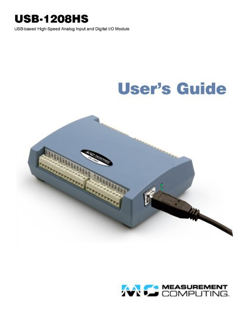
<strong>USB</strong>-<strong>1208HS</strong><br />
<strong>USB</strong>-based High-Speed Analog Input and<br />
Digital I/O Module<br />
<strong>User's</strong> <strong>Guide</strong><br />
Document Revision 1, November, 2008<br />
© Copyright 2008, Measurement Computing Corporation
Your new Measurement Computing product <strong>com</strong>es with a fantastic extra —<br />
Management <strong>com</strong>mitted to your satisfaction!<br />
Refer to www.mccdaq.<strong>com</strong>/execteam.html for the names, titles, and contact information of each key executive at Measurement<br />
Computing.<br />
Thank you for choosing a Measurement Computing product—and congratulations! You own the finest, and you can now enjoy<br />
the protection of the most <strong>com</strong>prehensive warranties and unmatched phone tech support. It’s the embodiment of our mission:<br />
• To provide PC-based data acquisition hardware and software that will save time and save money.<br />
Simple installations minimize the time between setting up your system and actually making measurements. We offer quick and<br />
simple access to outstanding live FREE technical support to help integrate MCC products into a DAQ system.<br />
Limited Lifetime Warranty: Most MCC products are covered by a limited lifetime warranty against defects in materials or<br />
workmanship for the life of the product, to the original purchaser, unless otherwise noted. Any products found to be defective in<br />
material or workmanship will be repaired, replaced with same or similar device, or refunded at MCC’s discretion. For specific<br />
information, please refer to the terms and conditions of sale.<br />
Harsh Environment Warranty® Program: Any Measurement Computing product that is damaged due to misuse, or any<br />
reason, may be eligible for replacement with the same or similar device for 50% of the current list price. I/O boards face some<br />
harsh environments, some harsher than the boards are designed to withstand. Contact MCC to determine your product’s<br />
eligibility for this program<br />
30 Day Money-Back Guarantee: Any Measurement Computing Corporation product may be returned within 30 days of<br />
purchase for a full refund of the price paid for the product being returned. If you are not satisfied, or chose the wrong product by<br />
mistake, you do not have to keep it.<br />
These warranties are in lieu of all other warranties, expressed or implied, including any implied warranty of merchantability or<br />
fitness for a particular application. The remedies provided herein are the buyer’s sole and exclusive remedies. Neither<br />
Measurement Computing Corporation, nor its employees shall be liable for any direct or indirect, special, incidental or<br />
consequential damage arising from the use of its products, even if Measurement Computing Corporation has been notified in<br />
advance of the possibility of such damages.<br />
Trademark and Copyright Information<br />
TracerDAQ, Universal Library, Harsh Environment Warranty, Measurement Computing Corporation, and the Measurement<br />
Computing logo are either trademarks or registered trademarks of Measurement Computing Corporation.<br />
Windows, Microsoft, and Visual Studio are either trademarks or registered trademarks of Microsoft Corporation<br />
LabVIEW is a trademark of National Instruments.<br />
CompactFlash is a registered trademark of SanDisk Corporation.<br />
XBee and XBee-PRO are trademarks of MaxStream, Inc.<br />
All other trademarks are the property of their respective owners.<br />
Information furnished by Measurement Computing Corporation is believed to be accurate and reliable. However, no<br />
responsibility is assumed by Measurement Computing Corporation neither for its use; nor for any infringements of patents or<br />
other rights of third parties, which may result from its use. No license is granted by implication or otherwise under any patent or<br />
copyrights of Measurement Computing Corporation.<br />
All rights reserved. No part of this publication may be reproduced, stored in a retrieval system, or transmitted, in any form by any<br />
means, electronic, mechanical, by photocopying, recording, or otherwise without the prior written permission of Measurement<br />
Computing Corporation.<br />
Notice<br />
Measurement Computing Corporation does not authorize any Measurement Computing Corporation product for use<br />
in life support systems and/or devices without prior written consent from Measurement Computing Corporation.<br />
Life support devices/systems are devices or systems which, a) are intended for surgical implantation into the body,<br />
or b) support or sustain life and whose failure to perform can be reasonably expected to result in injury.<br />
Measurement Computing Corporation products are not designed with the <strong>com</strong>ponents required, and are not subject<br />
to the testing required to ensure a level of reliability suitable for the treatment and diagnosis of people.<br />
HM <strong>USB</strong>-<strong>1208HS</strong>.doc<br />
3
Table of Contents<br />
Preface<br />
About this <strong>User's</strong> <strong>Guide</strong> ....................................................................................................................... 5<br />
What you will learn from this user's guide ......................................................................................................... 5<br />
Conventions in this user's guide ......................................................................................................................... 5<br />
Where to find more information ......................................................................................................................... 5<br />
Chapter 1<br />
Introducing the <strong>USB</strong>-<strong>1208HS</strong> ............................................................................................................... 6<br />
Software features ................................................................................................................................................ 7<br />
Chapter 2<br />
Installing the <strong>USB</strong>-<strong>1208HS</strong> ................................................................................................................... 8<br />
What <strong>com</strong>es with your <strong>USB</strong>-<strong>1208HS</strong> shipment? ................................................................................................ 8<br />
Hardware .......................................................................................................................................................................... 8<br />
Additional documentation ................................................................................................................................................. 8<br />
Unpacking the <strong>USB</strong>-<strong>1208HS</strong> .............................................................................................................................. 8<br />
Installing the software ........................................................................................................................................ 9<br />
Installing the hardware ....................................................................................................................................... 9<br />
Connecting the <strong>USB</strong>-<strong>1208HS</strong> to your system ................................................................................................................... 9<br />
Calibrating the <strong>USB</strong>-<strong>1208HS</strong> ............................................................................................................................. 9<br />
Chapter 3<br />
Functional Details ............................................................................................................................... 10<br />
Theory of operation - analog input acquisition modes ..................................................................................... 10<br />
Software paced mode .......................................................................................................................................................10<br />
Continuous scan mode .....................................................................................................................................................10<br />
External <strong>com</strong>ponents ........................................................................................................................................ 10<br />
<strong>USB</strong> connector .................................................................................................................................................................11<br />
Activity LED ...................................................................................................................................................................11<br />
Status LED .......................................................................................................................................................................11<br />
Screw terminals................................................................................................................................................................11<br />
Analog input terminals ..................................................................................................................................... 12<br />
Input configuration ..........................................................................................................................................................12<br />
External clock I/O terminals ............................................................................................................................. 13<br />
Digital I/O terminals ......................................................................................................................................... 13<br />
Internal pull-up/pull-down capability ..............................................................................................................................14<br />
Counter I/O terminals ....................................................................................................................................... 16<br />
Timer output terminal ....................................................................................................................................... 16<br />
Trigger input terminal ....................................................................................................................................... 16<br />
Retrigger ..........................................................................................................................................................................16<br />
Power terminals ................................................................................................................................................ 17<br />
Analog ground terminals .................................................................................................................................. 17<br />
Common ground terminals ............................................................................................................................... 17<br />
Chapter 4<br />
Specifications ...................................................................................................................................... 18<br />
4
About this <strong>User's</strong> <strong>Guide</strong><br />
Preface<br />
What you will learn from this user's guide<br />
This user's guide explains how to install, configure, and use the <strong>USB</strong>-<strong>1208HS</strong> so that you get the most out of its<br />
<strong>USB</strong> data acquisition features.<br />
This user's guide also refers you to related documents available on our web site, and to technical support<br />
resources.<br />
Conventions in this user's guide<br />
For more information on …<br />
Text presented in a box signifies additional information and helpful hints related to the subject matter you are<br />
reading.<br />
Caution! Shaded caution statements present information to help you avoid injuring yourself and others,<br />
damaging your hardware, or losing your data.<br />
< : > Angle brackets that enclose numbers separated by a colon signify a range of numbers, such as those assigned<br />
to registers, bit settings, etc.<br />
bold text<br />
italic text<br />
Bold text is used for the names of objects on the screen, such as buttons, text boxes, and check boxes. For<br />
example:<br />
1. Insert the disk or CD and click the OK button.<br />
Italic text is used for the names of manuals and help topic titles, and to emphasize a word or phrase. For<br />
example:<br />
The InstaCal installation procedure is explained in the Quick Start <strong>Guide</strong>.<br />
Never touch the exposed pins or circuit connections on the board.<br />
Where to find more information<br />
The following electronic documents provide helpful information relevant to the operation of the <strong>USB</strong>-<strong>1208HS</strong>.<br />
• MCC's Specifications: <strong>USB</strong>-<strong>1208HS</strong> (the PDF version of the Specifications chapter in this guide) is<br />
available on our web site at www.mccdaq.<strong>com</strong>/pdfs/<strong>USB</strong>-<strong>1208HS</strong>.pdf.<br />
• MCC's Quick Start <strong>Guide</strong> is available on our web site at<br />
www.mccdaq.<strong>com</strong>/PDFmanuals/DAQ-Software-Quick-Start.pdf.<br />
• MCC's <strong>Guide</strong> to Signal Connections is available on our web site at<br />
www.mccdaq.<strong>com</strong>/signals/signals.pdf.<br />
• MCC's Universal Library <strong>User's</strong> <strong>Guide</strong> is available on our web site at<br />
www.mccdaq.<strong>com</strong>/PDFmanuals/sm-ul-user-guide.pdf.<br />
• MCC's Universal Library Function Reference is available on our web site at<br />
www.mccdaq.<strong>com</strong>/PDFmanuals/sm-ul-functions.pdf.<br />
• MCC's Universal Library for LabVIEW User’s <strong>Guide</strong> is available on our web site at<br />
www.mccdaq.<strong>com</strong>/PDFmanuals/SM-UL-LabVIEW.pdf.<br />
<strong>USB</strong>-<strong>1208HS</strong> <strong>User's</strong> <strong>Guide</strong> (this document) is also available on our web site at<br />
www.mccdaq.<strong>com</strong>/PDFmanuals/<strong>USB</strong>-<strong>1208HS</strong>.pdf.<br />
5
Introducing the <strong>USB</strong>-<strong>1208HS</strong><br />
Chapter 1<br />
This user's guide contains all of the information you need to connect the <strong>USB</strong>-<strong>1208HS</strong> to your <strong>com</strong>puter and to<br />
the signals you want to measure.<br />
The <strong>USB</strong>-<strong>1208HS</strong> is a <strong>USB</strong> 2.0 high-speed device supported under popular Microsoft ® Windows ® operating<br />
systems. The <strong>USB</strong>-<strong>1208HS</strong> is <strong>com</strong>patible with both <strong>USB</strong> 1.1 and <strong>USB</strong> 2.0 ports, (although the speed of the<br />
module maybe limited when using <strong>USB</strong> 1.1 ports)<br />
With a multiplexed 13-bit A/D converter for all analog input channels, the <strong>USB</strong>-<strong>1208HS</strong> can sample:<br />
• up to eight single-ended analog inputs<br />
• up to four differential analog inputs<br />
A digital trigger lets you start analog input and / or analog output scans.<br />
The <strong>USB</strong>-<strong>1208HS</strong> also has 16 digital I/O connections. The port has 47 kΩ resistors that you can configure for<br />
pull-up/pull-down using a jumper inside the case. The default configuration is pull-down.<br />
You can configure each digital bit for either input (power on default) or output.<br />
The <strong>USB</strong>-<strong>1208HS</strong> also includes two 32-bit counters that can count TTL pulses, and one 32-bit timer.<br />
The <strong>USB</strong>-<strong>1208HS</strong> is powered by the +5 volt <strong>USB</strong> supply from your <strong>com</strong>puter, and requires no external power.<br />
The <strong>USB</strong>-<strong>1208HS</strong> is shown below. All I/O connections are made to the screw terminals located along each side<br />
of the <strong>USB</strong>-<strong>1208HS</strong>.<br />
6
<strong>USB</strong>-<strong>1208HS</strong> <strong>User's</strong> <strong>Guide</strong><br />
Introducing the <strong>USB</strong>-<strong>1208HS</strong><br />
<strong>USB</strong>-<strong>1208HS</strong> functions are illustrated in the block diagram shown here.<br />
Figure 1. <strong>USB</strong>-<strong>1208HS</strong> functional block diagram<br />
Software features<br />
For information on the features of InstaCal and the other software included with your <strong>USB</strong>-<strong>1208HS</strong>, refer to the<br />
Quick Start <strong>Guide</strong> that shipped with your device. The Quick Start <strong>Guide</strong> is also available in PDF at<br />
www.mccdaq.<strong>com</strong>/PDFmanuals/DAQ-Software-Quick-Start.pdf.<br />
Check www.mccdaq.<strong>com</strong>/download.htm for the latest software version.<br />
7
Installing the <strong>USB</strong>-<strong>1208HS</strong><br />
Chapter 2<br />
What <strong>com</strong>es with your <strong>USB</strong>-<strong>1208HS</strong> shipment?<br />
As you unpack your <strong>USB</strong>-<strong>1208HS</strong>, verify that the following <strong>com</strong>ponents are included.<br />
Hardware<br />
• <strong>USB</strong>-<strong>1208HS</strong><br />
• <strong>USB</strong> cable (2 meter length)<br />
Additional documentation<br />
In addition to this hardware user's guide, you should also receive the Quick Start <strong>Guide</strong> (available in PDF at<br />
www.mccdaq.<strong>com</strong>/PDFmanuals/DAQ-Software-Quick-Start.pdf). This booklet supplies a brief description of<br />
the software you received with your <strong>USB</strong>-<strong>1208HS</strong> and information regarding installation of that software.<br />
Please read this booklet <strong>com</strong>pletely before installing any software or hardware.<br />
Unpacking the <strong>USB</strong>-<strong>1208HS</strong><br />
As with any electronic device, you should take care while handling to avoid damage from static<br />
electricity. Before removing the <strong>USB</strong>-<strong>1208HS</strong> from its packaging, ground yourself using a wrist strap or by<br />
simply touching the <strong>com</strong>puter chassis or other grounded object to eliminate any stored static charge.<br />
If your <strong>USB</strong>-<strong>1208HS</strong> is damaged, notify Measurement Computing Corporation immediately by phone, fax, or<br />
email.<br />
• Phone: 508-946-5100 and follow the instructions for reaching Tech Support.<br />
• Fax: 508-946-9500 to the attention of Tech Support<br />
• Email: techsupport@mccdaq.<strong>com</strong><br />
For international customers, contact your local distributor. Refer to the "International Distributors" section on<br />
our contact web page (\www.mccdaq.<strong>com</strong>/contact/).<br />
8
<strong>USB</strong>-<strong>1208HS</strong> <strong>User's</strong> <strong>Guide</strong><br />
Installing the <strong>USB</strong>-<strong>1208HS</strong><br />
Installing the software<br />
Refer to the Quick Start <strong>Guide</strong> for instructions on installing the software on the Measurement Computing Data<br />
Acquisition Software CD. This booklet is available in PDF at www.mccdaq.<strong>com</strong>/PDFmanuals/DAQ-Software-<br />
Quick-Start.pdf.<br />
Installing the hardware<br />
Be sure you are using the latest system software<br />
Before you install your <strong>USB</strong>-<strong>1208HS</strong>, run Windows Update to update your operating system with the latest<br />
<strong>USB</strong> drivers.<br />
Install the MCC DAQ software before you install your board<br />
The driver needed to run your board is installed with the MCC DAQ software. Therefore, you need to install the<br />
MCC DAQ software before you install your board. Refer to the Quick Start <strong>Guide</strong> for instructions on installing<br />
the software.<br />
Connecting the <strong>USB</strong>-<strong>1208HS</strong> to your system<br />
To connect the <strong>USB</strong>-<strong>1208HS</strong> to your system, turn your <strong>com</strong>puter on, and connect the <strong>USB</strong> cable to a <strong>USB</strong> port<br />
on your <strong>com</strong>puter or to an external <strong>USB</strong> hub connected to your <strong>com</strong>puter. The <strong>USB</strong> cable provides power and<br />
<strong>com</strong>munication to the <strong>USB</strong>-<strong>1208HS</strong>.<br />
When you connect the <strong>USB</strong>-<strong>1208HS</strong> for the first time, a Found New Hardware dialog opens when the <strong>USB</strong>-<br />
<strong>1208HS</strong> interface is detected. The "Status" LED on the <strong>USB</strong>-<strong>1208HS</strong> turns on at this time, indicating the <strong>USB</strong>-<br />
<strong>1208HS</strong> is detected and installing on your <strong>com</strong>puter.<br />
When the dialog closes, the installation is <strong>com</strong>plete.<br />
Caution! Do not disconnect any device from the <strong>USB</strong> bus while the <strong>com</strong>puter is <strong>com</strong>municating with the<br />
<strong>USB</strong>-<strong>1208HS</strong>, or you may lose data and/or your ability to <strong>com</strong>municate with the <strong>USB</strong>-<strong>1208HS</strong>.<br />
If the Status LED turns off<br />
If the Status LED lights up but then turns off, the <strong>com</strong>puter has lost <strong>com</strong>munication with the <strong>USB</strong>-<strong>1208HS</strong>. To<br />
restore <strong>com</strong>munication, disconnect the <strong>USB</strong> cable from the <strong>com</strong>puter, and then reconnect it. This should restore<br />
<strong>com</strong>munication, and the LED should light up again.<br />
Calibrating the <strong>USB</strong>-<strong>1208HS</strong><br />
The <strong>USB</strong>-<strong>1208HS</strong> is shipped fully calibrated. Calibration coefficients are stored in EEPROM.<br />
Return the device to Measurement Computing Corporation when calibration is required. The normal calibration<br />
interval is once per year.<br />
9
Functional Details<br />
Chapter 3<br />
Theory of operation - analog input acquisition modes<br />
The <strong>USB</strong>-<strong>1208HS</strong> can acquire analog input data in two basic modes – software paced and continuous scan.<br />
Software paced mode<br />
You can acquire one analog sample at a time in software paced mode. You initiate the A/D conversion by<br />
calling a software <strong>com</strong>mand. The analog value is converted to digital data and returned to the <strong>com</strong>puter. You<br />
can repeat this procedure until you have the total number of samples that you want.<br />
The throughput sample rate in software paced mode is system-dependent, and can range from 33 S/s to<br />
4000 S/s.<br />
Continuous scan mode<br />
You can acquire data from up to eight channels in continuous scan mode. The analog data is continuously<br />
acquired, converted to digital values, and written to an onboard FIFO buffer on the <strong>USB</strong>-<strong>1208HS</strong> until you stop<br />
the scan. The FIFO buffer is serviced in blocks as the data is transferred from the <strong>USB</strong>-<strong>1208HS</strong> FIFO buffer to<br />
the memory buffer on your <strong>com</strong>puter.<br />
The maximum sampling rate is 1 MS/s aggregate over one-to-eight channels. You can start a continuous scan<br />
with either a software <strong>com</strong>mand or with an external hardware trigger event.<br />
External <strong>com</strong>ponents<br />
The <strong>USB</strong>-<strong>1208HS</strong> has the following external <strong>com</strong>ponents, as shown in Figure 2.<br />
• Screw terminal banks (two)<br />
• <strong>USB</strong> connector<br />
• LEDs<br />
Figure 2. <strong>USB</strong>-<strong>1208HS</strong> external <strong>com</strong>ponents<br />
10
<strong>USB</strong>-<strong>1208HS</strong> <strong>User's</strong> <strong>Guide</strong><br />
Functional Details<br />
<strong>USB</strong> connector<br />
The <strong>USB</strong> connector provides +5 V power and <strong>com</strong>munication. No external power supply is required.<br />
Activity LED<br />
The Activity LED indicates the <strong>com</strong>munication status of the <strong>USB</strong>-<strong>1208HS</strong>. It flashes when data is transferred,<br />
and is off when the <strong>USB</strong>-<strong>1208HS</strong> is not <strong>com</strong>municating. This LED uses up to 10 mA of current and cannot be<br />
disabled.<br />
Status LED<br />
The Status LED lights up when the <strong>USB</strong>-<strong>1208HS</strong> is detected and installed on your <strong>com</strong>puter.<br />
Screw terminals<br />
The <strong>USB</strong>-<strong>1208HS</strong> module's screw terminals provide the following connections:<br />
• Eight analog input connections (AIN0 to AIN7)<br />
• 16 digital I/O connections (DI00 to DI015)<br />
• 10 analog ground connections (AGND)<br />
• Six digital ground connections (GND)<br />
• One external clock input (AICKI) and one external clock output (AICKO) for analog inputs<br />
• One digital trigger input (TRIG)<br />
• Two counter inputs (CTR0, CTR1)<br />
• One timer output (TMR)<br />
• Two 5 V power output connections (+5 V)<br />
Figure 3. <strong>USB</strong>-<strong>1208HS</strong> screw terminal signals<br />
11
<strong>USB</strong>-<strong>1208HS</strong> <strong>User's</strong> <strong>Guide</strong><br />
Functional Details<br />
Analog input terminals<br />
You can connect up to eight analog input connections to the screw terminals labeled AIN0 through AIN7.<br />
Input configuration<br />
Analog signals are referenced to analog ground (AGND).<br />
Single-ended mode requires two wires:<br />
• The wire carrying the signal to be measured connects to AINx.<br />
• The second wire connects to AGND.<br />
Differential mode requires two wires plus a ground reference:<br />
• The wire carrying the positive portion of the differential signal to be measured connects to AINx.<br />
• The wire carrying the negative portion of the differential signal to be measured connects to AIN(x+1).<br />
• The analog ground reference wire connects to AGND.<br />
The terminal configurations for single-ended and differential modes are shown in the table below.<br />
Channel # 8 single-ended channels configuration 0 4 differential channels configuration<br />
V in + V in - V in + V in -<br />
0 AIN0 AGND AIN0 AIN1<br />
1 AIN1 AGND AIN2 AIN3<br />
2 AIN2 AGND AIN4 AIN5<br />
3 AIN3 AGND AIN6 AIN7<br />
4 AIN4 AGND - -<br />
5 AIN5 AGND - -<br />
6 AIN6 AGND - -<br />
7 AIN7 AGND - -<br />
In single-ended mode, the input voltage ranges are ±10 V, ±5 V, ±2.5 V, 0 to 10 V.<br />
In differential mode, the input voltage ranges are ±20 V, ±10 V, and ±5 V. The voltage level on each AINx<br />
input is limited to ±14 V<br />
The following image depicts a voltage source connected to a <strong>USB</strong>-<strong>1208HS</strong> configured for single-ended mode.<br />
Figure 4. Single-ended measurement connection<br />
12
<strong>USB</strong>-<strong>1208HS</strong> <strong>User's</strong> <strong>Guide</strong><br />
Functional Details<br />
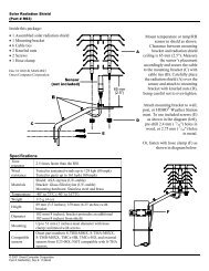
The following image depicts a Wheatstone bridge signal source connected to a <strong>USB</strong>-<strong>1208HS</strong> configured for<br />
differential mode.<br />
Figure 5. Differential measurement connection<br />
For more information on analog signal connections<br />
For more information on single-ended inputs, refer to the <strong>Guide</strong> to Signal Connections (this document is<br />
available on our web site at www.mccdaq.<strong>com</strong>/signals/signals.pdf).<br />
External clock I/O terminals<br />
Use the AICKI terminal to receive a sampling clock from an external source.<br />
Use the AICKO terminal to output the internal A/D sampling clock. When using an external clock, a pulse<br />
output generated by the external clock rising edge is also available at these terminals.<br />
Digital I/O terminals<br />
You can connect up to 16 digital I/O lines to screw terminals DIO0 through DIO15. Refer to the pinout diagram<br />
on page 11 for the location of these pins.<br />
The 16 DIO terminals have 47 k resistors that you can configure for pull-up/pull-down using a jumper inside the<br />
case. The default configuration is pull-down.<br />
You can use the <strong>USB</strong>-<strong>1208HS</strong> digital I/O terminals to detect the state of any TTL-level input. Refer to the<br />
switch circuit shown in Figure 6 and the schematic shown in Figure 7. If you set the switch to the +5 V input,<br />
DIO0 reads TRUE (1). If you move the switch to GND, DIO0 reads FALSE (0).<br />
13
<strong>USB</strong>-<strong>1208HS</strong> <strong>User's</strong> <strong>Guide</strong><br />
Functional Details<br />
Figure 6. Digital connection DI0 detecting the state of a switch<br />
DIO0<br />
GND<br />
+5V<br />
Figure 7. Schematic showing switch detection by digital channel DIO0<br />
Internal pull-up/pull-down capability<br />
Each of the 16 DIO bits on the <strong>USB</strong>-<strong>1208HS</strong> has a 47 kΩ pull-up/pull-down resistor. To configure these bits for<br />
either a +5 V pull-up or a 0 V pull-down option, you must open the <strong>USB</strong>-<strong>1208HS</strong> case to access the three-pin<br />
jumper labeled W34.<br />
The pull-up/pull-down voltage is <strong>com</strong>mon to all of the internal 47 kΩ resistors.<br />
To open the case and set the W34 jumper, do the following.<br />
1. Turn over the <strong>USB</strong>-<strong>1208HS</strong> and rest it on its top on a flat, stable surface.<br />
2. Peel off the four rubber feet on the bottom of the module to access the screws.<br />
3. Remove the four screws shown in Figure 8 from the bottom of the module.<br />
14
<strong>USB</strong>-<strong>1208HS</strong> <strong>User's</strong> <strong>Guide</strong><br />
Functional Details<br />
Figure 8. Location of screws connecting bottom and top sections of case<br />
4. Holding both the top and bottom sections of the module, turn it back over, rest it on the surface, and<br />
carefully remove the top section of the case.<br />
5. Set the jumper to either pull-up or pull-down (see Figure 9 and Figure 10).<br />
Figure 9. Location of W34 jumper (default pull-down setting shown)<br />
Figure 10. W34 jumper – pull-down and pull-up configurations<br />
6. Replace the top section of the case, and then fasten it to the bottom section with the four screws.<br />
15
<strong>USB</strong>-<strong>1208HS</strong> <strong>User's</strong> <strong>Guide</strong><br />
Functional Details<br />
For more information on digital signal connections<br />
For general information regarding digital signal connections and digital I/O techniques, refer to the <strong>Guide</strong> to<br />
Signal Connections (available on our web site at www.mccdaq.<strong>com</strong>/signals/signals.pdf).<br />
Counter I/O terminals<br />
The terminals provide connections to each 32-bit counter input channel (CTR0 and CTR1). Each counter can<br />
count frequencies of up to 20 MHz.<br />
Timer output terminal<br />
Use the TMR terminal to connect to the pulse width modulation (PWM) timer output.<br />
You can set the following timer output parameters through software:<br />
• pulse frequency<br />
• duty cycle (pulse width divided by the pulse period)<br />
• number of pulses to generate<br />
• time delay before starting the timer output after it's enabled<br />
• resting state of the output (idle high or idle low)<br />
The timer can generate a pulse output with a programmable frequency range of 0.00931 Hz up to 20 MHz.<br />
Both the period and time delay ranges are 50 ns to 107.4 seconds.<br />
Figure 11. <strong>USB</strong>-<strong>1208HS</strong> PWM timer channel<br />
Trigger input terminal<br />
The TRIG connection is an external digital trigger input. The trigger mode is software selectable for:<br />
• Level-sensitive or edge-sensitive<br />
• Rising or falling edge<br />
• High or low level<br />
The default setting at power up is edge sensitive, rising edge.<br />
Retrigger<br />
The acquisition uses the trigger settings for positive edge/negative edge and level-sensitive/edge-sensitive, but<br />
automatically re-arms the trigger after it is activated<br />
16
<strong>USB</strong>-<strong>1208HS</strong> <strong>User's</strong> <strong>Guide</strong><br />
Functional Details<br />
Power terminals<br />
You can use the two +5V connections to supply power to external devices or circuitry. These terminals can<br />
output up to 285 mA. Refer to the pinout diagram on page 11 for the location of this pin.<br />
Caution! The +5V terminals are outputs. Do not connect to an external power supply or you may damage<br />
the <strong>USB</strong>-<strong>1208HS</strong> and possibly the <strong>com</strong>puter.<br />
Analog ground terminals<br />
The 10 analog ground (AGND) connections provide a <strong>com</strong>mon ground for all analog I/O channels. Refer to the<br />
pinout diagram on page 11 for the location of the AGND terminal pins.<br />
Common ground terminals<br />
The six ground (GND) connections provide a <strong>com</strong>mon ground for the digital I/O, timer/counter I/O, timer, clock<br />
I/O, and the +5 V terminals. Refer to the pinout diagram on page 11 for the location of the GND terminals.<br />
17
Specifications<br />
Chapter 4<br />
All specifications are subject to change without notice.<br />
Typical for 25 °C unless otherwise specified.<br />
Specifications in italic text are guaranteed by design.<br />
Analog input<br />
Table 1. Analog input specifications<br />
Parameter Conditions Specification<br />
A/D converter<br />
Analog Devices AD7329 - 13-bit successive<br />
approximation type<br />
Input ranges Software-selectable per channel • Differential: ±20 V, ±10 V, ±5 V (The voltage<br />
level on each individual AIN input is limited to<br />
±14 V.)<br />
• SE: ±10 V, ±5 V, ±2.5 V, 0 – 10 V<br />
Number of channels<br />
4 differential/8 single-ended, software selectable<br />
Input configuration<br />
Multiplexed<br />
Channel gain queue 8 unique consecutive elements Software configurable range for each channel<br />
Absolute maximum input<br />
voltage<br />
CHx IN to GND.<br />
±25 V maximum (power on)<br />
±12 V maximum (power off)<br />
Input impedance<br />
35 MΩ minimum.<br />
Input bandwidth (-3 db) All input ranges 2 MHz typical<br />
Input leakage current<br />
±250 nA typical<br />
Input capacitance<br />
32 pf typical<br />
Offset error drift<br />
5 ppm/°C typical<br />
Gain error drift<br />
25 ppm/°C typical.<br />
Maximum working voltage<br />
(signal + <strong>com</strong>mon mode)<br />
Sampling rate<br />
Sample clock source<br />
±20 V ±14 V<br />
±10 V ±11 V<br />
±5 V ±5.5 V<br />
1 S/s to 1 MS/s, software programmable<br />
Internal A/D clock or AICKI<br />
Burst mode Software selectable, burst rate = 1µs<br />
Throughput Software paced 33 to 4000 S/s typical, system dependent<br />
Scan to PC memory<br />
1 MS/s maximum<br />
Resolution<br />
13 bits<br />
A/D no missing codes Differential Mode<br />
13 bits<br />
(uncalibrated)<br />
Single-ended Mode<br />
12 bits<br />
CMRR 60 Hz 74 dB typical<br />
Crosstalk<br />
Single-ended mode, All ranges, -62 dB typical<br />
250 kHz input signal<br />
Differential mode, all ranges,<br />
250 kHz input signal<br />
-78 dB typical<br />
18
<strong>USB</strong>-<strong>1208HS</strong> <strong>User's</strong> <strong>Guide</strong><br />
Specifications<br />
Range<br />
Table 2. Calibrated absolute accuracy<br />
Accuracy (mV)<br />
±20 V (differential mode) ±9.55 typical, ±13.18 maximum<br />
±10 V (differential mode) ±4.59 typical, ±6.23 maximum<br />
±5 V (differential mode) ±2.25 typical, ±2.75 maximum<br />
±10 V (single-ended mode) ±5.10 typical, ±8.06 maximum<br />
±5 V (single-ended mode) ±2.63 typical, ±4.03 maximum<br />
±2.5 V (single-ended mode) ±1.59 typical, ±2.70 maximum<br />
0 – 10 V (single-ended mode) ±3.29 typical, ±5.13 maximum<br />
Table 3 summarizes the noise performance for the <strong>USB</strong>-<strong>1208HS</strong>. Noise distribution is determined by gathering<br />
50 kS with inputs tied to ground at the user connector. Samples are gathered at the maximum specified<br />
sampling rate of 1 MS/s.<br />
Table 3. Noise performance<br />
Range Typical counts LSBrms<br />
±20 V (differential mode) 3 0.45<br />
±10 V (differential mode) 3 0.45<br />
±5 V (differential mode) 3 0.45<br />
±10 V (single-ended mode) 5 0.91<br />
±5 V (single-ended mode) 5 0.91<br />
±2.5 V (single-ended mode) 5 0.91<br />
0 – 10 V (single-ended mode) 5 0.91<br />
Table 4. Input settling time in µs, typical<br />
Condition Range ±1 LSB ±4 LSB ±8 LSB<br />
+ full-scale to – full-scale channel switch, same range to same range ±10 V 1.5 1.1 1.0<br />
±5 V 2.1 1.1 1.0<br />
±2.5 V 2.2 1.1 1.0<br />
0-10 V 2.6 1.1 1.0<br />
Digital input/output<br />
Table 5. Digital I/O specifications<br />
Digital type<br />
CMOS<br />
Number of I/O 16<br />
Configuration<br />
Each bit may be configured as input (power on default) or output<br />
Pull-up configuration<br />
The port has 47 kΩ resistors configurable as pull-ups or pull-downs via internal jumper<br />
(default setting is pull-down.)<br />
Digital I/O transfer rate<br />
(system-paced)<br />
Input high voltage<br />
Input low voltage<br />
Output high voltage<br />
Output low voltage<br />
Output current<br />
33 to 8000 port reads/writes or single bit reads/writes per second typical, system<br />
dependent.<br />
2.0 V minimum<br />
5.5 V absolute maximum<br />
0.8 V maximum<br />
–0.5 V absolute minimum<br />
0 V re<strong>com</strong>mended minimum<br />
4.4 V minimum (IOH = -50 µA)<br />
3.76 V minimum (IOH = -24 mA)<br />
0.1 V maximum (IOL = 50 µA)<br />
0.44 V maximum (IOL = 24 mA)<br />
±24 mA maximum per terminal (see "Power" section for additional information)<br />
19
<strong>USB</strong>-<strong>1208HS</strong> <strong>User's</strong> <strong>Guide</strong><br />
Specifications<br />
External trigger<br />
Table 6. External trigger specifications<br />
Parameter<br />
Trigger source<br />
Trigger mode<br />
Trigger latency<br />
Trigger pulse width<br />
Input type<br />
Schmitt trigger<br />
hysteresis<br />
Input high voltage<br />
Input low voltage<br />
Specification<br />
TRIG input<br />
Software configurable for edge or level sensitive, rising or falling edge, high or low level. Power<br />
on default is edge sensitive, rising edge.<br />
1 µs + 1 clock cycle maximum<br />
100 ns minimum<br />
Schmitt Trigger, 33 Ω series resistor and 47 kΩ pull-down to ground<br />
0.4 V to 1.2 V<br />
2.2 V minimum<br />
5.5 V absolute maximum<br />
1.5 V maximum<br />
–0.5 V absolute minimum<br />
0 V re<strong>com</strong>mended minimum<br />
External clock input/output<br />
Table 7. External clock I/O specifications<br />
Parameter<br />
Terminal names<br />
Terminal type<br />
Terminal descriptions<br />
Input clock rate<br />
Clock pulse width<br />
Input type<br />
Schmitt trigger<br />
hysteresis<br />
Input high voltage<br />
Input low voltage<br />
Output high voltage<br />
Output low voltage<br />
Output current<br />
Specification<br />
AICKI, AICKO<br />
AICKI: Input, active on rising edge<br />
AICKO: Output, power on default is 0 V, active on rising edge<br />
AICKI: Receives sampling clock from external source<br />
AICKO: Outputs internal sampling clock (A/D clock) or pulse generated from AICKI when in<br />
external clock mode<br />
1 MHz maximum.<br />
AICKI: 400 ns minimum<br />
AICKO: 400 ns minimum<br />
Schmitt trigger, 33 Ω series resistor, 47 kΩ pull-down to ground<br />
0.4 V to 1.2 V<br />
2.2 V minimum<br />
5.5 V absolute maximum<br />
1.5 V maximum<br />
–0.5 V absolute minimum<br />
0 V re<strong>com</strong>mended minimum<br />
4.4 V minimum (IOH = -50 µA)<br />
3.76 V minimum (IOH = -24 mA)<br />
0.1 V maximum (IOL = 50 µA)<br />
0.44 V maximum (IOL = 24 mA)<br />
±24 mA maximum per terminal (see "Power" section for additional information)<br />
20
<strong>USB</strong>-<strong>1208HS</strong> <strong>User's</strong> <strong>Guide</strong><br />
Specifications<br />
Counters<br />
Table 8. Counter specifications<br />
Counter terminal names CTR0, CTR1<br />
Counter type<br />
Event counter<br />
Number of channels 2<br />
Input type<br />
Schmitt trigger, 33 Ω series resistor, 47 kΩ pull-down to ground<br />
Schmitt trigger hysteresis 0.4 V to 1.2 V<br />
Input high voltage<br />
2.2 V minimum<br />
5.5 V absolute maximum<br />
Input low voltage<br />
1.5 V maximum<br />
–0.5 V absolute minimum<br />
0 V re<strong>com</strong>mended minimum<br />
Resolution<br />
32 bits<br />
Counter read/write rates 33 to 8000 reads/writes per second typical, system dependent<br />
(software paced)<br />
High pulse width<br />
25 ns minimum<br />
Low pulse width<br />
25 ns minimum<br />
Timer<br />
Table 9. Timer specifications<br />
Timer terminal name<br />
Timer type<br />
Output value<br />
Internal clock frequency<br />
Register widths<br />
High pulse width<br />
Low pulse width<br />
Output high voltage<br />
Output low voltage<br />
Output current<br />
TMR<br />
PWM output with count, period, delay, and pulse width registers<br />
Default state is idle low with pulses high, software selectable output invert<br />
40 MHz<br />
32 bits<br />
20 ns minimum<br />
20 ns minimum<br />
4.4 V minimum (IOH = -50 µA)<br />
3.76 V minimum (IOH = -24 mA)<br />
0.1 V maximum (IOL = 50 µA)<br />
0.44 V maximum (IOL = 24 mA)<br />
±24 mA maximum per terminal (see "Power" section for additional information)<br />
Memory<br />
Table 10. Memory specifications<br />
Data FIFO<br />
Non-volatile memory<br />
4 kS analog input<br />
32 KB (16 KB firmware storage, 16 KB calibration/user data)<br />
21
<strong>USB</strong>-<strong>1208HS</strong> <strong>User's</strong> <strong>Guide</strong><br />
Specifications<br />
Power<br />
Table 11. Power specifications<br />
Parameter Conditions Specification<br />
Operating modes<br />
Bus-powered, <strong>USB</strong> 5 V supply<br />
Supply current (see Note 1) Suspend mode
<strong>USB</strong>-<strong>1208HS</strong> <strong>User's</strong> <strong>Guide</strong><br />
Specifications<br />
Main connector and pin out<br />
Table 15. Main connector specifications<br />
Connector type<br />
Wire gauge range<br />
Screw terminal<br />
16 AWG to 30 AWG<br />
Table 16. Main connector pin out<br />
Pin Signal name Pin Signal name<br />
1 AIN0 29 NC<br />
2 AGND 30 NC<br />
3 AIN1 31 AGND<br />
4 AGND 32 NC<br />
5 AIN2 33 NC<br />
6 AGND 34 AGND<br />
7 AIN3 35 AICKI<br />
8 AGND 36 AICKO<br />
9 AIN4 37 NC<br />
10 AGND 38 NC<br />
11 AIN5 39 TRIG<br />
12 AGND 40 GND<br />
13 AIN6 41 CTR0<br />
14 AGND 42 CTR1<br />
15 AIN7 43 TMR<br />
16 AGND 44 GND<br />
17 empty 45 empty<br />
18 +5V 46 +5V<br />
19 GND 47 GND<br />
20 DIO0 48 DIO8<br />
21 DIO1 49 DIO9<br />
22 DIO2 50 DIO10<br />
23 DIO3 51 DIO11<br />
24 DIO4 52 DIO12<br />
25 DIO5 53 DIO13<br />
26 DIO6 54 DIO14<br />
27 DIO7 55 DIO15<br />
28 GND 56 GND<br />
23
Measurement Computing Corporation<br />
10 Commerce Way<br />
Suite 1008<br />
Norton, Massachusetts 02766<br />
(508) 946-5100<br />
Fax: (508) 946-9500<br />
E-mail: info@mccdaq.<strong>com</strong><br />
www.mccdaq.<strong>com</strong>