miniJET : A New Type of Micropile - Geosystems, LP
miniJET : A New Type of Micropile - Geosystems, LP
miniJET : A New Type of Micropile - Geosystems, LP

You also want an ePaper? Increase the reach of your titles
YUMPU automatically turns print PDFs into web optimized ePapers that Google loves.
<strong>miniJET</strong> ® : A <strong>New</strong> <strong>Type</strong> <strong>of</strong> <strong>Micropile</strong><br />
Dr. Donald A. Bruce 1 , Jeffrey J. Bean 2 , and Timothy J. Myers 3<br />
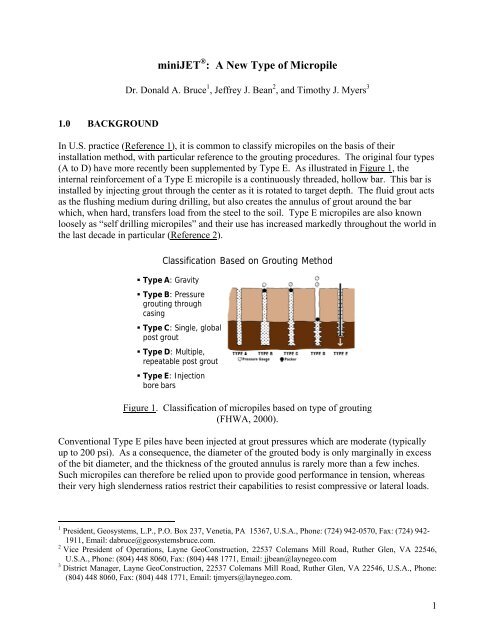
1.0 BACKGROUND<br />
In U.S. practice (Reference 1), it is common to classify micropiles on the basis <strong>of</strong> their<br />
installation method, with particular reference to the grouting procedures. The original four types<br />
(A to D) have more recently been supplemented by <strong>Type</strong> E. As illustrated in Figure 1, the<br />
internal reinforcement <strong>of</strong> a <strong>Type</strong> E micropile is a continuously threaded, hollow bar. This bar is<br />
installed by injecting grout through the center as it is rotated to target depth. The fluid grout acts<br />
as the flushing medium during drilling, but also creates the annulus <strong>of</strong> grout around the bar<br />
which, when hard, transfers load from the steel to the soil. <strong>Type</strong> E micropiles are also known<br />
loosely as “self drilling micropiles” and their use has increased markedly throughout the world in<br />
the last decade in particular (Reference 2).<br />
Classification Based on Grouting Method<br />
• <strong>Type</strong> A: Gravity<br />
• <strong>Type</strong> B: Pressure<br />
grouting through<br />
casing<br />
• <strong>Type</strong> C: Single, global<br />
post grout<br />
• <strong>Type</strong> D: Multiple,<br />
repeatable post grout<br />
• <strong>Type</strong> E: Injection<br />
bore bars<br />
Figure 1. Classification <strong>of</strong> micropiles based on type <strong>of</strong> grouting<br />
(FHWA, 2000).<br />
Conventional <strong>Type</strong> E piles have been injected at grout pressures which are moderate (typically<br />
up to 200 psi). As a consequence, the diameter <strong>of</strong> the grouted body is only marginally in excess<br />
<strong>of</strong> the bit diameter, and the thickness <strong>of</strong> the grouted annulus is rarely more than a few inches.<br />
Such micropiles can therefore be relied upon to provide good performance in tension, whereas<br />
their very high slenderness ratios restrict their capabilities to resist compressive or lateral loads.<br />
1 President, <strong>Geosystems</strong>, L.P., P.O. Box 237, Venetia, PA 15367, U.S.A., Phone: (724) 942-0570, Fax: (724) 942-<br />
1911, Email: dabruce@geosystemsbruce.com.<br />
2 Vice President <strong>of</strong> Operations, Layne GeoConstruction, 22537 Colemans Mill Road, Ruther Glen, VA 22546,<br />
U.S.A., Phone: (804) 448 8060, Fax: (804) 448 1771, Email: jjbean@laynegeo.com<br />
3 District Manager, Layne GeoConstruction, 22537 Colemans Mill Road, Ruther Glen, VA 22546, U.S.A., Phone:<br />
(804) 448 8060, Fax: (804) 448 1771, Email: tjmyers@laynegeo.com.<br />
1
This paper describes a new variant <strong>of</strong> the <strong>Type</strong> E pile, wherein the advantages <strong>of</strong> jet grouting<br />
technology are exploited to significantly increase the effective diameter <strong>of</strong> the pile as the bar is<br />
jetted into the soil, and to provide superior grout/soil skin friction potential. This development<br />
has been named by Layne GeoConstruction as <strong>miniJET</strong> ® .<br />
2.0 SYSTEM DESCRIPTION<br />
Many foundation remediations feature the construction <strong>of</strong> a jet grouted block which, depending<br />
on the structural loading requirements, may require steel reinforcement to help resist lateral<br />
and/or vertical stresses. Such steel reinforcements have traditionally been installed in holes<br />
drilled through the jet grouted block after it has reached a certain strength, and so <strong>of</strong>ten many<br />
days after the jet grouting has been completed. The time needed to sequence and conduct this<br />
reinforcement process can markedly impact the progress <strong>of</strong> such projects, especially when they<br />
involve restricted access such as in industrial facilities.<br />
In contrast, <strong>miniJET</strong> ® permits the jet grouting to be conducted and the columns to be internally<br />
reinforced in one operation. Figure 2 shows the components <strong>of</strong> the system, which are<br />
principally:<br />
<br />
<br />
<br />
Sacrificial drill bit with two or more nozzles to permit the grout to be ejected laterally (to jet<br />
grout the soil) and downwards (to facilitate penetration <strong>of</strong> the system). These drill bits can<br />
be modified as appropriate to match the site-specific soil conditions.<br />
Hollow, continuously-threaded steel bars <strong>of</strong> outside diameters 32-76 mm (Table 1). These<br />
can be provided in lengths <strong>of</strong> 1 to 6 m depending on specific project conditions.<br />
Steel couplers with special high pressure seals to prevent escape <strong>of</strong> grout during jetting.<br />
These components are shown in Photograph 1. Photograph 2 shows a variation suitable for use<br />
as a permanent prestressed anchor (also patented). In this variant the bar is galvanized and<br />
protected/debonded over its free length by a polyethylene sheath. Regarding the installation<br />
equipment, the drilling rig is equipped with a special swivel at the drillhead while, in order to<br />
enhance the control and quality <strong>of</strong> the operation, automated drilling and grouting parameter<br />
instrumentation is provided in the drill rig. These data are relayed telemetrically in real time to<br />
the project’s site <strong>of</strong>fice, as are the grouting data from the grout station. The grout station is<br />
typical <strong>of</strong> a conventional jet grouting installation, comprising an automated colloidal mixer,<br />
Tecniwell TWM20 or similar, which weigh batches bulk materials, an agitated storage tank, and<br />
a jet grouting pump, Tecniwell TW400 or similar.<br />
3.0 CASE HISTORY<br />
3.1 Background<br />
Modifications to an existing industrial facility in Florida required extensive jet grouting to<br />
provide support for a number <strong>of</strong> excavations, and to provide deep foundations for support <strong>of</strong> a<br />
new structure. Due to the design requirement to provide significant tensile and lateral capacity,<br />
the jet grouted mass required internal, vertical reinforcement in many areas.<br />
2
The specified structural design requirements for the jet grouted soil and the reinforcing steel<br />
were as follows:<br />
<br />
<br />
<br />
<br />
<br />
<br />
<br />
<br />
compression design load = 150 kips<br />
tension design load = 75 kips<br />
lateral design load = 20 kips<br />
minimum UCS jet grouted soil = 800 psi at 28 days<br />
maximum allowable compressive stress in jet grouted soil = 0.33f'c ≡ 264 psi<br />
yield strength <strong>of</strong> steel = 86 ksi<br />
maximum allowable compressive stress in steel = 28 ksi<br />
maximum allowable tensile stress in steel = 42 ksi<br />
Figure 2. MiniJET ® drill string assembly.<br />
Technical Features U.M. Rm32/15 Rm38/16 Rm51/29 Rm76/48s<br />
Outer Diameter mm 32 38 51 76<br />
Average Inner Diameter mm 14 16 28 48<br />
Ultimate Load kN 415 540 840 1800<br />
Yield Load kN 350 450 700 1450<br />
Suggested Working Load kN 230 300 450 970<br />
Weight Kg/m 4.5 6.2 9.5 20.5<br />
Delivery Lengths m 1.0 m – 1.5 m – 2.0 m – 3.0 m – 4.0 m – 6.0 m<br />
Table 1. Sizes and properties <strong>of</strong> reinforcement.<br />
3
<strong>miniJET</strong>® Hollow rebars<br />
Rebar-rebar coupling<br />
Drill bit with injection nozzles<br />
Nuts and anchoring plate<br />
Photograph 1. MiniJET ® components.<br />
Layne proposed to install the support <strong>of</strong> excavation columns using “traditional” jet grout<br />
methods (one fluid), but to install the foundation elements with the <strong>miniJET</strong> ® system. Further, a<br />
test program was designed to verify column diameter, strength and homogeneity and, by<br />
conducting load testing on <strong>miniJET</strong> ® columns, confirm their structural and geotechnical<br />
performance and verify design assumptions. Allowable side friction values <strong>of</strong> 5 psi and 12 psi<br />
were used in the design for the upper 25 feet (medium sands) and lower 15 feet (dense sands) <strong>of</strong><br />
soils, respectively. The jet grouted block was designed to bear on medium dense to dense sands.<br />
4
<strong>miniJET</strong>® PERMANENT ANCHOR<br />
protected by galvanizing treatment and polyethylene casing (on the free zone)<br />
Photograph 2. MiniJET ® permanent anchor components.<br />
3.2 Proposed Construction Details<br />
The thread bar was the 51-29 type, supplied in lengths <strong>of</strong> 1, 3 and 6 m. As shown in Table 1, this<br />
bar has a steel cross section <strong>of</strong> about 2.2 square inches and an ultimate load <strong>of</strong> 189 kips. Grout<br />
was anticipated to be a neat <strong>Type</strong> I/II mix <strong>of</strong> water:cement ratio 0.8. The columns would be<br />
installed by jetting from the top down. The drill bit had 3 nozzles, including two directed<br />
laterally to create the jet grouted column (Photograph 3). Upon reaching the target treatment<br />
depth, the bar would then be withdrawn to the elevation required to be reinforced. Jet grout<br />
parameters were selected to provide a nominal 2½-foot diameter column, and included an<br />
injection pressure <strong>of</strong> 400 bars.<br />
3.3 The Foreseen Test Program<br />
As shown in Figure 3, two types <strong>of</strong> columns would be installed: <strong>Type</strong> A (25 feet) and <strong>Type</strong> B<br />
(35 feet). One <strong>of</strong> these 18 columns was to be installed with a 76 mm diameter bar for<br />
compression and tension testing for research purposes.<br />
5
Photograph 3. MiniJET ® system being prepared for insertion.<br />
Figure 3. Test column layout, industrial facility, Florida.<br />
6
The test piles can be summarized as follows:<br />
TEST<br />
NUMBER<br />
OF<br />
COLUMNS<br />
DEPTH<br />
(FEET)<br />
REINFORCEMENT<br />
CONSTRUCTION<br />
LOADING/<br />
TESTING<br />
1 4 25 2 with 51 mm bar All <strong>miniJET</strong> ® Lateral<br />
2 4 35 2 with 51 mm bar All <strong>miniJET</strong> ® Lateral<br />
3 3 20 None Traditional Geometry<br />
4 1 25 51 mm bar <strong>miniJET</strong> ® Tension and<br />
Compression<br />
5 1 35 51 mm bar <strong>miniJET</strong> ® Tension and<br />
Compression<br />
6 1 35 76 mm bar <strong>miniJET</strong> ® Tension and<br />
Compression<br />
All 4 reaction anchors were to be installed with <strong>miniJET</strong> ® and 76 mm bar.<br />
The top <strong>of</strong> one <strong>of</strong> the 4-column groups was also to be exposed to observe geometry and<br />
homogeneity. Wet grab samples (3x6" moulds) were to be obtained on one <strong>of</strong> the two columns<br />
without reinforcement in each group: the other would be cored (3.25-inch sample) after testing,<br />
simply to provide some measure <strong>of</strong> correlation between the two methods. (Wet grab sampling is<br />
the standard quality assurance method in production.) Results to date from limited wet grab<br />
sampling are as follows:<br />
Compression<br />
DATE<br />
CAST<br />
STRENGTH (PSI)<br />
4 DAYS 5 DAYS 10 DAYS 14 DAYS<br />
5/28/2010 1650 1710 1750<br />
6/2/2010 1290 1520 1870<br />
3.4 Test Program Results<br />
Test data on Pile Test 4 (CONFIRM), are provided in Figure 4.<br />
Salient data on this 25-foot deep element, with a measured diameter <strong>of</strong> 40 inches as exposed by<br />
excavation (Photograph 4), are as follows:<br />
LOAD<br />
(KIPS)<br />
TOTAL VERTICAL<br />
MOVEMENT<br />
(INCHES)<br />
150 0.035<br />
350 0.137<br />
0 0.046<br />
7
0<br />
MiniJET® - Pile-Compression Load Test (25 ft - Test 4)<br />
Applied Loads (kips)<br />
0 50 100 150 200 250 300 350<br />
0.02<br />
Vertical Settlement (in)<br />
0.04<br />
0.06<br />
0.08<br />
0.1<br />
0.12<br />
0.14<br />
0.16<br />
Figure 4. MiniJET ® compression load test 4.<br />
Photograph 4. Exposed <strong>miniJET</strong> ® columns showing average 40-inch diameter.<br />
8
Test borings in the vicinity confirmed the pile to have been installed in medium dense sand (N =<br />
22). Based on previous experience, an ultimate grout/sand bond value <strong>of</strong> 15 psi is considered.<br />
This indicates that the test load was resisted by the upper 13 feet or so <strong>of</strong> the pile. Further, a<br />
strain gage fixed 2 feet from the bottom <strong>of</strong> the pile indicated practically no strain at the test load.<br />
Tension<br />
Figure 5 shows that the salient extension data are as follows:<br />
LOAD<br />
(KIPS)<br />
EXTENSION<br />
(INCHES)<br />
75 0.161<br />
150 0.517<br />
0 0.236<br />
The performance was lineal and indicative <strong>of</strong> slight progressive debonding. At 150 kips, it may<br />
be calculated that the amount <strong>of</strong> apparent debonding <strong>of</strong> the bar was 9.6 feet.<br />
0<br />
MiniJET® Pile-Tension Test (25 ft - Test 4)<br />
0 10 20 30 40 50 60 70 80 90 100 110 120 130 140 150 160<br />
0.1<br />
Vertical Movement (in)<br />
0.2<br />
0.3<br />
0.4<br />
0.5<br />
0.6<br />
Applied Loads (kips)<br />
Figure 5. MiniJET ® Tension Load Test 4.<br />
9
Lateral<br />
Data were obtained from 4 dial gages as follows:<br />
GAGE<br />
LOCATION<br />
(BELOW CAP)<br />
(INCHES)<br />
AT 40<br />
KIPS<br />
AT 80<br />
KIPS<br />
MOVEMENT<br />
RESIDUAL<br />
ELASTIC<br />
S1 25.75 0.038 0.137 0.113 0.024<br />
S2 21.50 0.016 0.096 0.072 0.026<br />
N3 20.25 0.010 0.034 0.009 0.025<br />
N4 19.25 0.011 0.038 0.012 0.026<br />
The jack reacted between the two column groups and was located 39.5 inches below the top <strong>of</strong><br />
the pile cap. Note that a severe rain storm affected the readings <strong>of</strong> S1 and S2 in mid-test.<br />
However, as is shown above, the elastic deflection as measured at each gage at 80 kips (twice<br />
working load) was remarkably consistent.<br />
Clearly the results <strong>of</strong> the axial and lateral tests were extremely impressive, with movements<br />
being very small and practically elastic, within the load range tested.<br />
4.0 PRODUCTION<br />
For the 19 different foundation/excavation locations, there were a total <strong>of</strong> 325 “conventional”<br />
support <strong>of</strong> excavation jet grout columns (totaling 6,175 lft) and 437 <strong>miniJET</strong> ® columns (totaling<br />
12,948 lft) approximately 90% <strong>of</strong> which were reinforced.<br />
These elements ranged from 14-54 feet in depth, with most being 25 feet or 35 feet deep. The<br />
results from the test program permitted the overall length <strong>of</strong> columns to be reduced by over<br />
4,400 lft, or about 30% <strong>of</strong> the originally designed scheme. The use <strong>of</strong> <strong>miniJET</strong> ® also provided<br />
significant schedule and sequencing advantages.<br />
REFERENCES<br />
1. Federal Highway Administration (2000). “<strong>Micropile</strong> Design and Construction Guidelines:<br />
Implementation Manual” Publication No. FHWA-SA-97-070, June.<br />
2. MacLean, D. (2010). “Typical Case History Using a Titan <strong>Micropile</strong>,” DFI-ADSC<br />
<strong>Micropile</strong>s Seminar: Industry Trends and Developments, Toronto, ON, Canada, Deep<br />
Foundations Institute, April 8.<br />
10