ROCK ANCHORS â THEN AND NOW - Geosystems, LP
ROCK ANCHORS â THEN AND NOW - Geosystems, LP
ROCK ANCHORS â THEN AND NOW - Geosystems, LP

Create successful ePaper yourself
Turn your PDF publications into a flip-book with our unique Google optimized e-Paper software.
Sept<br />
2003<br />
GEOSYSTEMS, L.P<br />
(724) 942-0570<br />
<strong>ROCK</strong> <strong>ANCHORS</strong> – <strong>THEN</strong> <strong>AND</strong> <strong>NOW</strong><br />
Dr. Donald A. Bruce
Sept<br />
2003<br />
GEOSYSTEMS, L.P<br />
(724) 942-0570<br />
1. Background<br />
2. Geotechnical Design<br />
3. Construction<br />
3.1 Drilling<br />
3.2 Water Pressure Testing<br />
3.3 Grouting<br />
3.4 Tendon<br />
4. Stressing and Testing<br />
5. As-Built Records<br />
6. Overview
Sept<br />
2003<br />
1. Background<br />
• Large dam, Pacific Northwest<br />
• 142 vertical anchors installed in 1975, to resist sliding<br />
• “Button head” wire tendons, total length 55 to 168<br />
feet.<br />
• Design Working Load 205 to 1490 kips<br />
• Long term performance monitored via 4-wire 4<br />
“minitendons”<br />
• Original records available, permitting comparison with<br />
current PTI (1996) Recommendations
Sept<br />
2003<br />
2. Geotechnical Design<br />
Then:<br />
• Uniform bond distribution<br />
• τ w = 100 to 130 psi<br />
• “Volume of rock cone”<br />
theory for overall stability
Sept<br />
2003 GEOSYSTEMS, L.P.<br />
Now:<br />
Exactly the Same!<br />
However…
Sept<br />
2003<br />
Anchor Design Approach from Piling<br />
Ultimate load = Ultimate bond stress x Bond area<br />
Bond area = π x Diameter x Bond length<br />
therefore<br />
Ultimate load ∝ Bond length
Normal Anchor Design<br />
ASSUMPTION<br />
Stress distribution of a simple design approach<br />
Ultimate load = π x d x L x τ ult<br />
This means load ∝ fixed length<br />
Sept<br />
2003<br />
This is not a true statement.
Sept<br />
2003<br />
Actual normal anchor load distribution during<br />
loading
Sept<br />
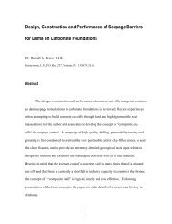
2003<br />
1<br />
(f eff) EFFICIENCY FACTOR<br />
0.9<br />
0.8<br />
0.7<br />
0.6<br />
0.5<br />
0.4<br />
0.3<br />
0.2<br />
0.1<br />
f eff = 1.6L -0.57<br />
0<br />
0 5 10 15 20 25<br />
FIXED LENGTH (m)<br />
Distribution of anchor efficiency with fixed length<br />
showing best fit curve (Barley, 1995)
Comparison of the load distribution of a normal anchor<br />
with that of an early single bore multiple anchor<br />
Sept<br />
2003
Normal 10 m anchor capacity vs.<br />
10 m Multiple anchor capacity<br />
comprising four 2.5 m units<br />
Sept<br />
2003<br />
10-m m Efficiency factor = 0.43<br />
2.5-m m Efficiency factor = 0.95<br />
Therefore, SBMA has<br />
0.95/0.43 = 2.2 x normal anchor capacity<br />
in same borehole
Load distribution developed in a SBMA<br />
Where ground Strength improves with depth<br />
Sept<br />
2003<br />
Realistic consideration from circa 1992
Sept<br />
2003<br />
3.1 Drilling<br />
Then:<br />
• Diamond drilling in concrete<br />
• Rotary or rotary percussive in rock<br />
• Deviation monitoring (< 1 in 100)<br />
• Pressure grouting<br />
• Maintain full logs
Sept<br />
2003<br />
3.1 Drilling<br />
Now:<br />
• Diamond drilling only for reinforced concrete or<br />
very weak structures<br />
• Use down-the<br />
the-hole hole hammer<br />
– Deviation control<br />
– Speed<br />
– Vibrations/pneumatic fracture<br />
• MWD
Rock Drilling Methods<br />
1. Rotary<br />
Sept<br />
2003<br />
• High rpm, low torque, low thrust (blind or core)<br />
• Low rpm, high torque, high thrust<br />
2. Rotary Percussive<br />
• Top Hammer<br />
• Down-the<br />
the-hole hole Hammer<br />
– Direct circulation<br />
– Reverse circulation<br />
– Dual fluid drilling<br />
– Water hammers<br />
3. Rotary Vibratory (Sonic)
Sept<br />
2003<br />
Sonic Drilling: Advantages<br />
• Can provide continuous, relatively<br />
undisturbed cores in soil (75-250 mm<br />
diameter) and rock<br />
• Very high penetration rates<br />
• Readily penetrates obstructions<br />
• Depths to 150 m<br />
• Can easily convert to other types of<br />
drilling<br />
• No flush in overburden, minor amounts<br />
in rock
Sept<br />
2003<br />
Circulation Type and Application<br />
• Up-hole velocity (UHV) > “sinking velocity”<br />
• UHV (m/min) = 1274 x Flush Pump Rate (Liters/min)<br />
D2 – d2 (mm)<br />
where D = drill hole diameter (in mm)<br />
d = drill string diameter (in mm)<br />
• Typical UHV<br />
– Air, or air/water “mist”: 1500 m/s (max 2100 m/s<br />
– Water: 36 m/s (max 120 m/s)<br />
– Low to medium viscosity mud: 30 m/s<br />
– Very thick mud: 18 m/s<br />
– Foam: 12 m/s
Sept<br />
2003<br />
OVERBURDEN<br />
DRILLING METHODS<br />
Overburden is<br />
STABLE*<br />
Overburden is<br />
UNSTABLE*<br />
Solid<br />
Stem<br />
Auger<br />
Open Hole<br />
(with Rock<br />
Drilling<br />
Methods)<br />
Hollow<br />
Stem<br />
Auger<br />
“Combination”<br />
Methods<br />
Slurry<br />
Supported<br />
Methods<br />
Cased<br />
Methods<br />
HIGH --– Environmental ---- LOW<br />
Concerns<br />
LOW ----- Presence of -- SEVERE<br />
Obstructions<br />
Bentonite<br />
Polymer<br />
Self<br />
Hardening<br />
Sonic<br />
Single<br />
Tube<br />
Rotary<br />
Duplex<br />
Rotary<br />
Percussive<br />
Duplex<br />
(Concentric)<br />
Rotary<br />
Percussive<br />
Duplex<br />
(Eccentric)<br />
Double<br />
Head<br />
Duplex<br />
LOW --------------------------------------------------------------------------- Presence of Obstructions --------------------------------------------------------------------- SEVERE<br />
LOW ------------------------------------------------------------------------- Technological Sophistication ----------------------------------------------------------------------- HIGH<br />
VERY HIGH ------------------------------------------------------------------------------------ Instantaneous Penetration Rate Potential ---------------------------------------------------------------------------------- LOWER<br />
*Stability refers to the overburden’s ability to maintain the shape and size of the drilled hole without detriment to the<br />
surrounding ground after withdrawal of the drilling system.
Sept<br />
2003<br />
Circulation Type and Application<br />
(Continued)<br />
• Air vs. Water – Rotary vs. Rotary Percussion<br />
• Guideline for selection<br />
– Provide clean hole<br />
– Enhance penetration rate<br />
– Minimize tool wear<br />
– Consistent with purpose of hole<br />
– Minimal damage to formation and/or structures<br />
– Environmentally compatible<br />
– Reconsider options if “lost flush” occurs
Borehole Deviation<br />
Potential for deviation depends on<br />
• Nature of subsurface conditions<br />
• Nature of surface conditions (“drill platform”)<br />
• Nature of drilling method and tooling<br />
• Accuracy of initial drill set up<br />
• Inclination and length of hole<br />
• Expertise and technique of driller<br />
• Nature and length of guide casing<br />
• Use of special stabilizing devices<br />
Sept<br />
2003<br />
Note: : Different deviations are acceptable<br />
depending on project requirements and technique.
Table 2. Summary of recorded drill hole deviations from more recently published data<br />
SOURCE<br />
APPLICATION<br />
METHOD<br />
RECORDED DEVIATION<br />
Bruce (1989)<br />
Dam anchors in rock and concrete<br />
Down-the-hole hammer and rotary<br />
Target 1 in 60 to 1 in 240<br />
Mainly 1 in 100 or better achieved<br />
Bruce and Croxall<br />
(1989)<br />
Deep grout holes in fill<br />
Double head<br />
Duplex<br />
Achieved 1 in 50 to 1 in 1000 (average 1<br />
in 80)<br />
BS 8081 (1989)<br />
Ground anchors<br />
General<br />
1 in 30 “should be anticipated”<br />
Houlsby (1990)<br />
Grout holes in rock<br />
Percussion<br />
Up to 1 in 10 at 60 m<br />
Weaver (1991)<br />
Grout holes in rock<br />
Down-the-hole hammer<br />
1 in 100 increasing to 1 in 20 with<br />
increasing depth (70 m)<br />
“Dry Drilled Percussion”<br />
1 in 6<br />
Bruce et al. (1993)<br />
Dam anchors in rock and concrete<br />
Down-the-hole hammer<br />
Target 1 in 125: consistently achieved as<br />
little as 1 in 400<br />
Xanthakos et al. (1994)<br />
General in soil<br />
Drive Drilling<br />
Up to 1 in 14<br />
Percussion<br />
Up to 1 in 20<br />
Down-the-hole<br />
Up to 1 in 50<br />
Kutzner (1996)<br />
Grout holes in rock<br />
Rotary Blind<br />
Rotary Core<br />
Up to 1 in 33<br />
Up to 1 in 100<br />
“Unavoidable”<br />
Wireline Core<br />
Up to 1 in 200<br />
Horizontal holes in soil<br />
Percussive Duplex<br />
Less than 1 in 100<br />
PTI (1996)<br />
Tiebacks<br />
General statement<br />
Up to 1 in 30 normally acceptable<br />
Sept<br />
2003<br />
FHWA (1999)<br />
General<br />
High Speed Rotary<br />
Top Drive Percussion<br />
2 to 5 in 100<br />
< 5 to 20 in 100 depending on depth
Measurement of Deviation<br />
• Not routinely conducted<br />
• Real time vs. retrospective<br />
• Various principles<br />
– Optical<br />
– Photographic<br />
– Magnetic<br />
– Gyroscopic<br />
Scope for “project-specific” adaptations<br />
• Scope for “project<br />
Sept<br />
2003
Sept<br />
2003<br />
Recording of Drilling Progress and<br />
Parameters<br />
• Value of real time continuous monitoring<br />
for design purposes (manual vs.<br />
automatic)<br />
• Look for “exceptions and unexpecteds”<br />
[Weaver, 1991]<br />
• Indication of progressive improvement<br />
(e.g., denser, less permeable conditions)<br />
• Concept of specific energy<br />
• Several generations/evolutions
Sept<br />
2003<br />
Calculation of Specific Energy<br />
e = F + 2 π N T<br />
A AR<br />
where<br />
e = specific energy (kJ/m3)<br />
F = thrust (kN)<br />
A = cross sectional area of hole (m2)<br />
N = rotational speed (revolutions/second)<br />
T = torque (kN-m)<br />
R = penetration rate (m/sec)
Sept<br />
2003<br />
3.2 Water Pressure Testing<br />
Then:<br />
• Full length<br />
• 0.5 gpm at 60 psi<br />
(more typical 0.001 gal/inch diameter/ft/min<br />
at 5 psi)<br />
• Very conservative criterion
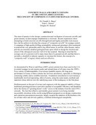
3.2 Water Pressure Testing<br />
Now:<br />
• Knowledge of fissure control on<br />
permeability<br />
• 2.5 gal at 5 psi excess<br />
40<br />
• Gravity grout<br />
35<br />
Sept<br />
2003<br />
Gravity grout<br />
Gallons in 10 Minutes<br />
30<br />
25<br />
20<br />
15<br />
10<br />
5<br />
0<br />
ANCHOR WATERTIGHTNESS CRITERIA<br />
0 20 40 60 80 100 120 140 160 180 200 220 240 260<br />
Length ( ft )<br />
PTI 1996<br />
PTI 1974 8"<br />
PTI 1974 12"<br />
PTI 1974 15"<br />
Germany Eder Dam<br />
Hanna<br />
Germany Bornhard &<br />
Sperber<br />
Switzerland Buro<br />
Switzerland Moshler &<br />
Matt<br />
UK Devonport<br />
European Standard<br />
prEN1537:1997
Sept<br />
2003<br />
3.3 Grouting<br />
Then:<br />
• Proprietary non-shrink grout for first stage<br />
• Water:cement ratio ≤ 0.45<br />
• Pre-construction testing<br />
• High speed, high shear mixer<br />
• Tremie grout
Sept<br />
2003<br />
3.3 Grouting<br />
Now: Same except:<br />
• No use of preblend cements<br />
• Focus on fluid property testing<br />
• Often single stage grouting
Sept<br />
2003<br />
Trial Mixes<br />
• Cement selection<br />
• Compatibility with<br />
admixtures<br />
• Minimize bleed<br />
• Water:cement ratio<br />
• Stability
Trial Batches<br />
• Workability<br />
–Flow<br />
– Stability<br />
• Measure Performance<br />
– Bleed<br />
–Density<br />
–Strength<br />
• Mixing Time<br />
– Manufacturer’s Recommendations<br />
– ≅ 4-5 5 Minutes<br />
– Mixer Optimization Process<br />
Sept<br />
2003
Sept<br />
2003<br />
3.4 Tendon<br />
Then:<br />
• Contractor selection<br />
• Use of wire/button head<br />
• No corrosion protection other than grout
Sept<br />
2003<br />
3.4 Tendon<br />
Now:<br />
• Tendon specified<br />
• No use of wire tendons<br />
• Class 1 – Class 2 Corrosion Protection<br />
• Use of epoxy coated strand
How to provide the needed<br />
Corrosion Protection?<br />
• Extrusion Sheathed Strand<br />
– Complete filling of all Interstices with Corrosion<br />
Inhibitor – No Voids<br />
• Epoxy Coated Strand<br />
– ASTM A-882, A<br />
revised 2002<br />
– Coating is a barrier to corrosion,<br />
– If damaged, Local Galvanic Cell may occur<br />
• Corrugated Outer Duct<br />
– Barrier to corrosion elements<br />
– Larger dia. duct is job site installed.<br />
Sept<br />
2003<br />
– Larger dia. drill hole may be required.
Sept<br />
2003<br />
How to provide the unbonded length?<br />
• Sheath Extruded onto the Strand<br />
– Assured Corrosion Protection<br />
– High Force Transmission Efficiency<br />
• Slipped on Tube Sheath<br />
– Larger accumulated diameter of anchor<br />
tendon bundle<br />
• Two stage grouting – no sheath<br />
– Additional step of grouting after stressing
Corrosion Protection Decision Tree<br />
Service Life<br />
Temporary<br />
24 Months<br />
Agressive<br />
Yes<br />
No<br />
Yes<br />
No<br />
Class 2<br />
None<br />
Class 1<br />
Failure<br />
Serious<br />
Non Serious<br />
Class 1<br />
In Place Cost<br />
Sept<br />
2003<br />
Inexpensive<br />
Class 1<br />
Expensive<br />
Class 2
Sept<br />
2003<br />
Corrosion Protection Requirements<br />
PROTECTION REQUIREMENTS<br />
CLASS ANCHORAGE UNBONDED TENDON BOND<br />
LENGTH<br />
LENGTH<br />
I 1. TRUMPET 1. GREASE-FILLED 1. GROUT-FILLED<br />
ENCAPSULATED 2. COVER IF SHEATH, OR ENCAPSULATION,<br />
TENDON EXPOSED 2. GROUT-FILLED OR<br />
SHEATH, OR 2. EPOXY<br />
3. EPOXY FOR<br />
FULLY BONDED<br />
<strong>ANCHORS</strong><br />
II 1. TRUMPET 1. GREASE-FILLED<br />
GROUT 2. COVER IF SHEATH, OR GROUT<br />
PROTECTED EXPOSED 2. HEAT SHRINK<br />
TENDON SLEEVE
Sept<br />
2003<br />
4. Stressing and Testing<br />
Then:<br />
• Progressive simple loading to<br />
100% Design Working Load<br />
• No cycling<br />
• Lock off at ≤ 70% GUTS<br />
• Lift off test<br />
• No creep test
Sept<br />
2003<br />
4. Stressing and Testing<br />
Now:<br />
• Proof and Performance Tests<br />
• Analysis of elastic data<br />
• Creep test<br />
• Lift off<br />
• Lock off ≤ 60% GUTS
Anchor Tests - General<br />
1. Pre-production Tests<br />
Carried out on one or two anchors, to confirm the grout / ground bond<br />
stress assumed. These tests are carried out on non-production<br />
anchors.<br />
2. Performance Tests<br />
Carried out on the first two to three anchors, plus a minimum of 2%<br />
thereafter, to confirm that the anchors meet the detailed design and<br />
specification. These tests are carried out on production anchors.<br />
3. Proof Tests<br />
Carried out an all other production anchors, to confirm that the anchors<br />
meet the general requirements of the design and specification.<br />
Plus:<br />
Supplementary Extended Creep Tests<br />
At least two extended tests shall be made on permanent<br />
Sept<br />
2003<br />
anchors in soils having a Plasticity Index greater than 20.
Performance Tests<br />
To Determine:<br />
a) whether the anchor has sufficient<br />
load carrying capacity,<br />
b) that the apparent free tendon<br />
length has been satisfactorily<br />
established,<br />
c) the magnitude of the residual<br />
movement,and<br />
d) that the rate of creep stabilizes<br />
within the specified limits.<br />
Acceptance Criteria:<br />
133% of design load<br />
minimum > 80% Free length<br />
maximum < (Free length + 50% of bond length)<br />
no absolute criterion, but must be determined to<br />
evaluate the elastic movement for calculating “<br />
above”<br />
< 1 mm at Test Load during 1 to 10 minutes<br />
or if this is exceeded<br />
< 2 mm at test Load for a period of 6 to 60<br />
minutes<br />
Cycling loading to: 25%, 50%, 75%, 100%, 120%, 133%(TL) of the design load(DL)<br />
Load is decreased to alignment load (AL) after each cycle<br />
After acceptance , adjust to lock-off load<br />
Sept<br />
2003
Graphical Analysis of Performance Test Data<br />
δ e<br />
Line A: 80% Free Length<br />
Line B: Free Length + 50% Bond Length<br />
AL (0.10)<br />
Elastic<br />
Movement<br />
1.33<br />
1.00<br />
0.50<br />
0.25<br />
0.75<br />
1.20<br />
Residual<br />
Movement<br />
0<br />
Load<br />
DL<br />
δ r<br />
Sept<br />
2003
Proof Tests<br />
To Determine:<br />
a) whether the anchor has sufficient<br />
load carrying capacity,<br />
b) that the apparent free tendon<br />
length has been satisfactorily<br />
established, and<br />
d) that the rate of creep stabilizes<br />
within the specified limits.<br />
Acceptance Criteria:<br />
133% of design load<br />
minimum > 80% Free length<br />
maximum < (Free length + 50% bond length<br />
< 1 mm at Test Load during 1 to 10 minutes<br />
or if this is exceeded<br />
< 2 mm at test Load for a period of 6 to 60<br />
minutes<br />
Incrementally loading to: 25%, 50%, 75%, 100%, 120%,<br />
133%(TL) of the design load(DL)<br />
After Sept acceptance , adjust to lock-off load<br />
2003
Graphical Analysis of Proof Test Data<br />
δ e<br />
Line A: 80% Free Length<br />
Line B: Free Length + 50% Bond Length<br />
AL (0.10)<br />
Elastic<br />
Movement<br />
0.50<br />
1.33<br />
1.00<br />
0.25<br />
0.75<br />
1.20<br />
0<br />
Residual<br />
Movement<br />
Load<br />
DL<br />
δ r<br />
Sept<br />
2003
Supplementary Extended Creep Tests<br />
To Determine:<br />
that there is no indication that future<br />
unacceptable movement or creep failure is<br />
probable.<br />
A family of creep curves is plotted on a semi-logarithmic chart.<br />
Creep movement < 1 mm at Test load during 1 to 10 minutes<br />
or<br />
Creep movement < 2 mm at Test load during 6 to 60 minutes<br />
Testing in accordance with the schedule in Table 8.3<br />
. Note: Epoxy coated strand itself has a significant value and thus<br />
should be accounted for when assessing the creep of the anchor<br />
Sept<br />
2003
Special Considerations for<br />
Epoxy Coated Strand Anchors<br />
• ASTM A-882 A<br />
alone is not quality guarantee.<br />
• Inspect strands during fabrication<br />
Sept<br />
2003<br />
Patch any coating holidays or holes.<br />
• Very abrasive surface causes need to protect men<br />
and equipment<br />
• Strand has more curvature memory making<br />
handling and fabrication more difficult.<br />
• Coiling very much more difficult due to friction of<br />
strands when tendon bent.<br />
• Handling of anchors may cause coating damage.<br />
• Efficient patching methods needed.<br />
• Stressing has extra requirements and must be very<br />
disciplined. Little tolerance for variation.<br />
Slippages have occurred causing rejected anchors.
Sept<br />
2003<br />
5. As Built Records<br />
Then:<br />
• Focus on drilling logs via cores<br />
• Grout strength data (cubes)<br />
• Load-extension data<br />
Now: Much enhanced, e.g.,<br />
• MWD<br />
• Fluid grout tests<br />
• Stressing data<br />
• [Computers help]
Sept<br />
2003<br />
6. Overview<br />
<strong>THEN</strong><br />
<strong>NOW</strong><br />
Geotechnical design<br />
Same – equally conservative<br />
Construction<br />
• Drilling<br />
• Water pressure testing<br />
• Grouting<br />
• Tendon<br />
Stressing and Testing<br />
Investigation<br />
Production<br />
<br />
Better<br />
material<br />
knowledge<br />
<br />
<br />
As-Built Records<br />
Equally good, but quality<br />
reflects construction process