high capacity and fully removable soil anchors - Geosystems, L.P.
high capacity and fully removable soil anchors - Geosystems, L.P.
high capacity and fully removable soil anchors - Geosystems, L.P.

You also want an ePaper? Increase the reach of your titles
YUMPU automatically turns print PDFs into web optimized ePapers that Google loves.
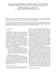
First presented at the 27th Annual Conference on Deep Foundations<br />
The Time Factor in Design <strong>and</strong> Construction of Deep Foundations, San Diego, CA<br />
HIGH CAPACITY AND FULLY REMOVABLE SOIL ANCHORS<br />
Anthony D. Barley, Single Bore Multiple Anchor Ltd., Harrogate, U.K.<br />
Donald A. Bruce, <strong>Geosystems</strong>, L.P., Venetia, PA, U.S.A.<br />
Mary Ellen C. Bruce, geotechnica, s.a., Inc., Venetia, PA, U.S.A.<br />
J. Christopher Lang, Lang Tendons, Inc., Toughkenamon, PA, U.S.A.<br />
Over 60,000 multiple <strong>anchors</strong> have been used internationally since their<br />
introduction in the early 1990s, including 1000 in the United States. The<br />
multiple anchor system comprises a “multiple” of “unit” <strong>anchors</strong> installed<br />
within a single borehole – each unit anchor being staggered within the<br />
borehole length to mobilize its own <strong>capacity</strong> independently of the other<br />
unit <strong>anchors</strong>. These systems offer <strong>high</strong>er <strong>capacity</strong> than conventional<br />
<strong>anchors</strong> with identical bond lengths due to superior load transfer<br />
efficiency. The use of <strong>high</strong>er <strong>capacity</strong> <strong>anchors</strong> may allow reduction in<br />
the number of <strong>anchors</strong> required on a project, which results in time <strong>and</strong><br />
cost benefits to the anchor installer, contractor, <strong>and</strong> the owner. Fully<br />
<strong>removable</strong> temporary multiple <strong>anchors</strong> are available, <strong>and</strong> have been<br />
used with consistent success. Three case histories are discussed<br />
<strong>high</strong>lighting the use of these systems.<br />
INTRODUCTION<br />
The advantages of using anchor/tiebacks for<br />
the temporary retention of vertical faces of<br />
deep <strong>and</strong> underground construction were first<br />
realized in the 1960s. Their usage grew<br />
greatly after successful anchoring in <strong>soil</strong> <strong>and</strong><br />
weak rocks was achieved. The major benefit<br />
provided by these anchored systems was the<br />
open excavation area created by eliminating<br />
horizontal or raked struts, which generally<br />
inhibit rapid construction within the site area.<br />
In the majority of instances the constructed<br />
retaining walls can be relatively stiff but the<br />
spacing of anchor tiebacks both horizontally<br />
<strong>and</strong> vertically is frequently controlled by the<br />
anchor/tieback working <strong>capacity</strong> rather than<br />
full exploitation of the wall stiffness.<br />
With regard to environmental aspects, anchor<br />
tiebacks although installed for temporary<br />
usage generally provide a permanent<br />
“contamination” of the ground in which they<br />
are founded. This zone is frequently below<br />
adjacent structures or streets <strong>and</strong> <strong>high</strong>ways<br />
<strong>and</strong> the existence of the remaining steel<br />
anchor/tieback members may jeopardize any<br />
further underground construction in that zone.<br />
DEVELOPMENTS IN ANCHOR<br />
TECHNOLOGY<br />
Significant advances in anchor technology<br />
have been achieved in the past 30 years,<br />
resulting in increased anchor capacities <strong>and</strong><br />
<strong>fully</strong> <strong>removable</strong> anchor systems that<br />
accommodate some of the constraints<br />
imposed by urban construction. The following<br />
examples are provided.<br />
Increase in Anchor Capacity<br />
Working capacities of anchor/tiebacks in <strong>soil</strong>s<br />
<strong>and</strong> weak rock have been gradually increased<br />
due to changes in anchor physical dimensions<br />
<strong>and</strong> installation techniques, <strong>and</strong> increased<br />
underst<strong>and</strong>ing of load transfer mechanisms.<br />
Some of the significant enhancements of the<br />
technology that have provided these increased<br />
capacities include:<br />
• Increased bore diameter (100 to 300 mm<br />
range).<br />
• Use of underreaming systems (500 to 700<br />
mm underreaming tools available).<br />
• Use of end-of-casing pressure grouting<br />
(typically up to 10 bar).<br />
• Use of post-grouting systems with<br />
grouting repeatability (up to 60 bar).<br />
• Availability of more refined grouting<br />
plants.<br />
• Development of more powerful drilling<br />
rigs to allow <strong>high</strong> production <strong>and</strong><br />
reduction of breakdowns.<br />
• Availability of more experienced<br />
personnel with an underst<strong>and</strong>ing of<br />
construction techniques <strong>and</strong> load transfer<br />
mechanisms.<br />
• Development of fixed length geometries<br />
that optimize efficiency of load transfer.
These developments have resulted in an<br />
increase in working <strong>capacity</strong> for normal<br />
<strong>anchors</strong> from the 25 to 60 tonnes typically<br />
available in the 1960s (Littlejohn, 1970), to the<br />
50 to 100 tonnes now typically obtainable.<br />
Inefficiency of load transfer in conventional<br />
<strong>anchors</strong> is due in part to non-uniform load<br />
distribution along the bond length. It is <strong>fully</strong><br />
acknowledged by researchers who have<br />
investigated grout/ground load transfer that the<br />
distribution of stress along the fixed anchor is<br />
non-uniform due to general incompatibility<br />
between elastic moduli of the anchor tendon,<br />
anchor grout, <strong>and</strong> the ground (Ostermayer,<br />
1975; Littlejohn <strong>and</strong> Bruce, 1977; Fujita et al.,<br />
1978; Shields et al., 1987; Casanovas, 1989;<br />
Ludwig <strong>and</strong> Weatherby, 1989; Mecsi, 1995<br />
<strong>and</strong> 1997; Briaud et al., 1998). In the vast<br />
majority of conventional <strong>anchors</strong>, after initial<br />
loading, the bond stress is concentrated over<br />
the proximal end of the fixed anchor, while the<br />
distal end of the fixed length remains<br />
unstressed. As load is increased, the ultimate<br />
bond stress at the proximal end of the fixed<br />
length along either (or both) the steel/grout<br />
interface or the grout/ground interface is<br />
exceeded. At that moment, the bond stress<br />
reduces to a residual value at that location, the<br />
<strong>capacity</strong> at that location of the anchor is<br />
reached, <strong>and</strong> movement occurs.<br />
Subsequently, the <strong>capacity</strong> in that section of<br />
the anchor decreases, <strong>and</strong> the load is<br />
transferred towards the distal end of the fixed<br />
length. As load on the anchor is further<br />
increased, the bond stress concentration zone<br />
progresses further along the fixed anchor.<br />
Just prior to pull-out, the load is concentrated<br />
at the distal end of the fixed length. Figure 1a<br />
depicts this load transfer phenomenon,<br />
referred to as “progressive debonding.” The<br />
area under the bond stress distribution line<br />
represents the ultimate load in the anchor. It<br />
can be seen that the load does not increase<br />
uniformly with increasing length. The effects<br />
of this phenomenon were understood <strong>and</strong><br />
diagrammatically quantified as early as 1975.<br />
General research suggested that little increase<br />
in anchor <strong>capacity</strong> was achieved in fixed<br />
lengths in excess of 23 feet (7 m).<br />
Although the debonding problem <strong>and</strong> the<br />
severity of its effects have been known for<br />
years, it was not until the development of the<br />
single bore multiple anchor system (SBMA)<br />
around 1988, that a method was devised to<br />
eliminate the detrimental effects of progressive<br />
debonding. The SBMA system utilizes a<br />
“multiple” of “unit” <strong>anchors</strong> installed in one<br />
borehole: the fixed length of each unit anchor<br />
being staggered within the borehole length to<br />
mobilize its own <strong>capacity</strong> independently of the<br />
other unit <strong>anchors</strong>. The load is transferred<br />
equally between each unit anchor <strong>and</strong> the<br />
grout over a multiple of short lengths<br />
throughout the bond zone, thereby allowing<br />
the same load to be carried by each unit<br />
anchor simultaneously. A comparison of load<br />
distribution along an SBMA <strong>and</strong> a conventional<br />
anchor is depicted in Figure 1b.<br />
The enhanced load transfer in the SBMA<br />
practically eliminates or reduces to negligible<br />
proportions the occurrence of progressive<br />
debonding, <strong>and</strong> thereby substantially<br />
increases the efficiency of the anchor.<br />
To quantify the effect of progressive<br />
debonding, data were evaluated from over<br />
60 investigatory <strong>anchors</strong> with different fixed<br />
lengths installed <strong>and</strong> tested in a range of <strong>soil</strong><br />
conditions (clays, silty clays, <strong>and</strong> s<strong>and</strong>y clays,<br />
boulder clay <strong>and</strong> glacial till) (Barley 1995, <strong>and</strong><br />
1997; Barley <strong>and</strong> Windsor, 2000). From this<br />
research, the concept of an “efficiency factor”<br />
was developed, which suggests the following<br />
simple mathematical expression to reduce the<br />
ultimate bond stress (τ ult ) by accounting for the<br />
occurrence of progressive debonding:<br />
T ult = π d L f eff τ ult<br />
Where,<br />
T ult = ultimate anchor <strong>capacity</strong><br />
d = borehole diameter<br />
L = fixed length or unit fixed length<br />
f eff = efficiency factor, which itself is a<br />
function of L<br />
τ ult = ultimate bond stress of a short fixed<br />
length<br />
Efficiency factors from these investigatory<br />
<strong>anchors</strong> were plotted versus fixed length as<br />
shown in Figure 2.<br />
The best fit curve is represented by the<br />
following equation:<br />
f eff = 1.6 L -0.57<br />
where, L = fixed length or unit fixed length (in<br />
meters)<br />
As an example, assuming a conventional<br />
anchor with a 40-foot length (13 m), the<br />
efficiency factor is<br />
f eff = 1.6 x (13 m) -0.57<br />
= 0.37
a)<br />
b)<br />
Figure 1. Load transfer mechanisms in a) a conventional anchor <strong>and</strong><br />
b) an SBMA with equal overall fixed lengths.<br />
Figure 2. Efficiency factor versus fixed length (Barley, 1995). (Best fit curve shown.)
An SBMA with four fixed anchor lengths of<br />
10 feet (i.e., overall fixed length of 40 feet), the<br />
efficiency factor for each 10-foot unit anchor<br />
(3 m) is:<br />
f eff = 1.6 x (3 m) -0.57<br />
= 0.86<br />
i.e., an SBMA with 4 unit <strong>anchors</strong> will be 2.3<br />
times more efficient than a conventional<br />
anchor with a single 40-foot fixed length (0.86 /<br />
0.37 = 2.3).<br />
This advanced design approach allows the<br />
fixed length of each unit anchor to be tailored<br />
for the <strong>soil</strong> conditions encountered at a<br />
particular depth. Hence a multiple of unit<br />
<strong>anchors</strong> may efficiently utilize various unit<br />
fixed length of 8 to 10 feet (2.5 to 3 m) with<br />
corresponding efficiency factors ranging from<br />
0.80 to 0.95.<br />
Approximately 60,000 unit <strong>anchors</strong> have been<br />
installed (approximately 1000 in the United<br />
States). About 68 investigation <strong>anchors</strong> have<br />
been loaded to failure, <strong>and</strong> ultimate capacities<br />
of 200 to 500 tonnes achieved in <strong>soil</strong>s<br />
(Simpson, 2001). The working capacities of<br />
SBMAs range typically from 80 to 200 tonnes,<br />
which is two to three times that of conventional<br />
anchor systems installed using the same<br />
construction techniques albeit with longer<br />
overall fixed lengths.<br />
Removable Anchor Systems<br />
The use of <strong>removable</strong> steel tensile members<br />
for temporary anchor applications has been<br />
developed since the mid 1970s. Two basic<br />
types of systems are available:<br />
• one that allows the removal of only the<br />
steel member from the free<br />
(debonded) length; <strong>and</strong><br />
• one that allows the removal of the<br />
steel member from the entire length of<br />
the anchor.<br />
Methods of removing the steel member from<br />
only the free length have been applied for<br />
many years by either unscrewing an anchor<br />
bar from the debonded length, or by providing<br />
some sort of a weakness in the str<strong>and</strong>s at the<br />
debonded/bonded length junction. Although<br />
simple in principle, the implementation of this<br />
system has been difficult, <strong>and</strong> as a result,<br />
much supposedly “<strong>removable</strong>” free length<br />
steel has been left in place over the past<br />
30 years. A limited number of specialist<br />
tendon suppliers <strong>and</strong> contractors now have<br />
“proven” <strong>removable</strong> systems available (Herbst,<br />
1997).<br />
The removal of both free <strong>and</strong> fixed length steel<br />
has until recently been extremely difficult to<br />
achieve. Loading the tendon to overcome<br />
grout/ground interface stress, which has<br />
typically been designed to factor of safety<br />
against bond failure in excess of 1.5, is<br />
practically impossible. Therefore, the limited<br />
number of <strong>removable</strong> systems available<br />
attempt to destroy or crack the grout column,<br />
thereby reducing tendon/grout bond <strong>capacity</strong><br />
prior to pull out. Rates of success of tendon<br />
removal using these methods vary<br />
considerably.<br />
For low <strong>capacity</strong> <strong>anchors</strong> (less than 20 tonnes)<br />
the use of an auger type system incorporated<br />
in the tensile member is readily available <strong>and</strong><br />
generally successful (“Chance” system). A<br />
recently developed method that allows<br />
complete removal of the fixed <strong>and</strong> free lengths<br />
of multiple str<strong>and</strong> tendons has been more<br />
consistently successful. This system,<br />
developed from the concept of the recovery of<br />
a climbing rope during rappelling, utilizes a<br />
looped str<strong>and</strong>, sheathed <strong>and</strong> greased over its<br />
entire length (Photograph 1).<br />
Load is transferred from the loop to a saddle<br />
<strong>and</strong> a short compression member within the<br />
corrugated sheath which in turn transfers the<br />
load to grout <strong>and</strong> the ground. The tails of the<br />
str<strong>and</strong> stick out of the borehole. The total<br />
elimination of bond between the steel str<strong>and</strong><br />
<strong>and</strong> the grout facilitates the removal of the<br />
entire length of str<strong>and</strong>. This concept was<br />
adapted to SBMAs by incorporating a series of<br />
loops with saddles positioned at staggered<br />
depths in the borehole (Stockhammer <strong>and</strong><br />
Trummer, 1995; Barley et al., 1999). During<br />
use, both tails are loaded simultaneously.<br />
During removal, one tail is loaded, <strong>and</strong> the<br />
str<strong>and</strong> slides around the saddle <strong>and</strong> pulls out<br />
of the borehole. Photograph 2 shows an<br />
extracted str<strong>and</strong>. The helical formation results<br />
from the friction along the saddle during<br />
pullout.
Photograph 1. Looped str<strong>and</strong>s of <strong>removable</strong> SBMAs.<br />
Photograph 2. Extracted str<strong>and</strong> of a removal anchor.
THE BENEFITS OF ENHANCED ANCHOR<br />
TECHNOLOGY<br />
Benefits of Increased Anchor Capacity<br />
The cost of the installation of an anchor is<br />
generally controlled by:<br />
• Time to set up <strong>and</strong> start drilling<br />
• Drilling time through structure or<br />
materials (wall or fill)<br />
• Drilling time for free length of anchor<br />
• Drilling time for fixed length of anchor<br />
• Tendon material costs<br />
• Grouting time <strong>and</strong> materials costs<br />
• Anchor head material<br />
• Stressing time<br />
The SBMA achieves time <strong>and</strong> cost savings by<br />
providing two times the working load of a<br />
normal anchor, thereby halving the number of<br />
anchor. The net savings are not necessarily<br />
halved, but are on the order of 20%. The<br />
drilling <strong>and</strong> installation time is practically<br />
halved while the total tendon <strong>and</strong> anchor head<br />
costs are of the same order as the original<br />
scheme. Stressing time is increased for a<br />
multiple anchor, although the total time is<br />
undoubtedly less than that required to stress<br />
twice the number of conventional <strong>anchors</strong>.<br />
Cost savings may be shared generally<br />
between the anchor installer, the contractor,<br />
<strong>and</strong> the owner.<br />
Fewer <strong>anchors</strong> also provide time savings due<br />
to a reduction in the number of wall<br />
penetration points (less ducts, reinforcement<br />
penetration or holes to be burned) <strong>and</strong> a<br />
reduction in the risk of operations in locations<br />
where <strong>high</strong> ground water level is present.<br />
Fewer rows of <strong>anchors</strong> reduce disruption<br />
during excavation <strong>and</strong> reduce the number of<br />
waling levels. Perhaps the most significant<br />
benefit is the reduction of the overall<br />
construction period, which may be as much as<br />
40% <strong>and</strong> is generally to the advantage of the<br />
Contractor <strong>and</strong> Owner.<br />
Benefits of Removable Anchor Systems<br />
Row(s) of temporary anchor tendons left in<br />
place can inhibit future construction especially<br />
in urban areas. Conventional piling rigs,<br />
diaphragm walling rigs, or boring rigs can<br />
easily penetrate existing grout <strong>and</strong> plastic<br />
components (saddle from <strong>removable</strong><br />
systems), although ab<strong>and</strong>oned steel<br />
components may prove impenetrable. In<br />
many of the world’s larger cities, the use of<br />
temporary <strong>anchors</strong> for <strong>soil</strong>/wall retention is<br />
only tolerated if removal of the steel tendons<br />
can be guaranteed (e.g., Edinburgh, London,<br />
Hong Kong, Singapore, <strong>and</strong> Berlin).<br />
CASE HISTORIES<br />
Although many projects have achieved these<br />
time <strong>and</strong> cost savings since the introduction of<br />
the system in the early 1990s, three<br />
international projects provide suitable<br />
illustration.<br />
Excavation for Central Station, Hong Kong<br />
At Central Station in Hong Kong, a 20-m deep<br />
excavation 120 m long <strong>and</strong> 75 m wide was<br />
retained using up to 5 levels of 200-tonne<br />
working <strong>capacity</strong> multiple <strong>anchors</strong> (probably<br />
the <strong>high</strong>est <strong>capacity</strong> <strong>soil</strong> <strong>anchors</strong> ever<br />
installed). The general contractor would not<br />
have considered an anchor solution if such<br />
working capacities could not be achieved<br />
(Barley et al., 1999). Closely-spaced horizontal<br />
struts were used as retention in the adjacent<br />
section (Photograph 3). Structures constructed<br />
in the open-space excavation were completed<br />
3 months earlier than those in the adjacent<br />
strutted section.<br />
Deep Excavation, Singapore<br />
In Singapore, a vertical bored pile wall is<br />
currently being retained by 150-tonne working<br />
load <strong>anchors</strong> (Barley <strong>and</strong> Kiat, 2002)<br />
(Photograph 4). The use of these <strong>high</strong><br />
<strong>capacity</strong> <strong>anchors</strong> allowed the contractor to<br />
reduce the number of <strong>anchors</strong> in half with a<br />
considerable overall time saving. The<br />
performance of the <strong>anchors</strong> <strong>and</strong> the integrity of<br />
the corrosion protection system were<br />
demonstrated in test <strong>anchors</strong> <strong>and</strong> gun barrel<br />
tests prior to production.<br />
Slope Stabilization, Natchez, MS<br />
In Natchez, MS, slope stabilization <strong>and</strong><br />
retention projects have been undertaken to<br />
arrest slope erosion along the Mississippi<br />
River. Stabilization of the slope has been<br />
difficult due to the need to achieve adequate<br />
bond stresses in the ultra-sensitive finegrained<br />
loess <strong>soil</strong> at the retention level. A trial<br />
multiple anchor was installed, <strong>and</strong> an anchor<br />
system of adequate <strong>capacity</strong> for permanent<br />
<strong>soil</strong> retention was provided (Photograph 5)<br />
(Fairweather, 1997).
Photograph 3. 200-tonne working <strong>capacity</strong> multiple <strong>anchors</strong> at Central Station in Hong Kong.<br />
Photograph 4. 150-tonne working load <strong>anchors</strong> allowed the original number of<br />
80-tonne <strong>anchors</strong> to be reduced by half.
Photograph 5. High <strong>capacity</strong> SBMAs in difficult “loess” <strong>soil</strong>s in Natchez, MS.<br />
SUMMARY<br />
Significant time <strong>and</strong> cost benefits have been<br />
realized through the use of <strong>high</strong> <strong>capacity</strong><br />
single bore multiple <strong>anchors</strong> (SBMAs).<br />
Advancements in anchor technology <strong>and</strong><br />
installation techniques have resulted in<br />
working capacities of up to 200 tonnes. These<br />
<strong>high</strong> anchor capacities achievable in <strong>soil</strong> <strong>and</strong><br />
weak rocks have allowed the number of<br />
<strong>anchors</strong> required on specific projects to be<br />
reduced by half, which correlates to a cost<br />
savings of approximately 20% on the anchor<br />
installation.<br />
Removable multiple <strong>anchors</strong> are available that<br />
employ a loop <strong>and</strong> saddle arrangement to<br />
permit the extraction of the str<strong>and</strong> from within<br />
the corrugated sheath after usage. The<br />
removal of the steel allows future construction<br />
to progress unencumbered by the ab<strong>and</strong>oned<br />
tendons. Additional information on <strong>high</strong><br />
<strong>capacity</strong> <strong>and</strong> <strong>removable</strong> multiple <strong>anchors</strong> is<br />
available on-line at www.SBMAsystems.com<br />
<strong>and</strong> www.theanchorman.com.<br />
REFERENCES<br />
BARLEY, A., <strong>and</strong> S.C. KIAT. (2002). “Slope<br />
Stabilisation by Soil Nails <strong>and</strong> Replacement by<br />
bored pile wall <strong>and</strong> Multiple Anchors” Ground<br />
Engineering, February.<br />
BARLEY, A.D. (1995). “Theory <strong>and</strong> practice of<br />
the Single Bore Multiple Anchor system.”<br />
Anker in Theorie <strong>and</strong> Praxis. Proc. Int.<br />
Symposium Salzburg Okt. 1995. Balkema<br />
Rotterdam, Pp. 293-301.<br />
BARLEY, A.D. (1997). “The single bore<br />
multiple anchor system” Proc. Intern. Conf.<br />
Ground Anchorages <strong>and</strong> Anchored Structures.<br />
London, pp. 65-75.<br />
BARLEY, A.D. (2000). “Trial <strong>soil</strong> nails for<br />
tunnel face support in London Clay <strong>and</strong> the<br />
detected influence of tendon stiffness <strong>and</strong><br />
bond length on load transfer.” Proceedings of<br />
the third International <strong>Geosystems</strong>, London,<br />
June.<br />
BARLEY, A.D., <strong>and</strong> C.R. WINDSOR. (2000).<br />
“Recent advances in ground anchor <strong>and</strong><br />
ground reinforcement technology with<br />
reference to the development of the art.”<br />
GeoEng2000, International Conference on<br />
Geotechnical <strong>and</strong> Geological Engineering,<br />
Melbourne, November 19-12, pp. 1048-1094.<br />
BARLEY, A.D., W.D. PAYNE, <strong>and</strong> P.L.<br />
MCBARRON. (1999). “Six rows of <strong>high</strong><br />
<strong>capacity</strong> <strong>removable</strong> <strong>anchors</strong> support deep <strong>soil</strong><br />
mix cofferdam.” Proceedings 12 European<br />
Conference on Soil Mechanics <strong>and</strong><br />
Geotechnical Engineering, Amsterdam,<br />
Geotechnical Engineering for Transportation
Infrastructure. (Eds. Barends, et al.)<br />
Rotterdam, pp. 1465-1471.<br />
BRIAUD, J., W. POWERS, <strong>and</strong> D.<br />
WEATHERBY. (1998). “Should Grouted<br />
Anchors have Short Tendon Bond Lengths”,<br />
Journal of Geotechnical <strong>and</strong><br />
Geoenvironmental Engineering, ASCE,<br />
February <strong>and</strong> Discussion (September, 1999).<br />
CASANOVAS. (1989). “Bond strength <strong>and</strong><br />
bearing <strong>capacity</strong> of injected <strong>anchors</strong>: a new<br />
approach.” Proceedings of the 12 th<br />
Conference SMFE, Rio de Janeiro, Vol. 2.<br />
FAIRWEATHER, V. (1997). “Ground Anchor<br />
Advance.” Civil Engineering, December.<br />
FUJITA, K., K. UEDA, <strong>and</strong> M. KUSABUKA.<br />
(1978). “A Method to Predict the Load<br />
Displacement Relationship of Ground<br />
Anchors.” Revue Francaise de Geotechnique<br />
No. 3. 58-62<br />
Anchorages. Proceedings, Institution of Civil<br />
Engineers, London, September 18-20, pp.<br />
141-151.<br />
SHIELDS, D.R., H. SCHNABEL, <strong>and</strong> D.E.<br />
WEATHERBY. (1978). “Load transfer in<br />
pressure injected <strong>anchors</strong>.” Journal of the<br />
Geotechnical Engineering Division,<br />
September.<br />
SIMPSON, D. (2001). “Dublin Port Weighs<br />
Anchors.” European Foundations, Winter.<br />
STOCKHAMMER, P., <strong>and</strong> F. TRUMMER.<br />
(1995). “Der Wiedergewinnbare Litzenanker<br />
System Keller. Anchors in Theory <strong>and</strong><br />
Practice, Proceedings International<br />
Symposium, Salzburg, October. Balkema<br />
Rotterdam, pp. 373-376.<br />
HERBST, T.F. (1997). “Removable ground<br />
<strong>anchors</strong> – Answer for urban excavations.”<br />
Proceedings of the International Conference<br />
on Ground Anchorages <strong>and</strong> Anchored<br />
Structures,” London, pp. 197-205.<br />
LITTLEJOHN, G.S. (1970). “Anchorages in<br />
Soils- Some Empirical Design Rules,” The<br />
Consulting Engineer, May.<br />
LITTLEJOHN, G.S., <strong>and</strong> D.A. BRUCE. (1977).<br />
“Rock Anchors - State of the Art.” Foundation<br />
Publications, Essex, Engl<strong>and</strong>, 50 pp.<br />
(Previously published in Ground Engineering<br />
in 5 parts, 1975-1976.)<br />
LUDWIG H.P., <strong>and</strong> D.E. WEATHERBY.<br />
(1989). “Behaviour of a Tieback in Cohesive<br />
Soil,” 12 th International Conference on Soil<br />
Mechanics <strong>and</strong> Foundation. Rio de Janeiro,<br />
Vol. 2.<br />
MECSI, J. (1995). “Analysis of grouted <strong>soil</strong><br />
<strong>anchors</strong>.” Proceedings of International<br />
Symposium Anchors in Theory <strong>and</strong> Practice,<br />
Salzburg, October, Balkema, Rotterdam.<br />
MECSI, J. (1997). “Some practical <strong>and</strong><br />
theoretical aspects of grouted <strong>soil</strong> <strong>anchors</strong>.<br />
Institution of Civil Engineers Conference on<br />
Ground Anchors <strong>and</strong> Anchored Structures,<br />
London, March 1997, pp. 119-130.<br />
OSTERMAYER, H. (1974). “Construction,<br />
carrying behaviour <strong>and</strong> creep characteristics of<br />
ground <strong>anchors</strong>.” Diaphragm Walls <strong>and</strong>