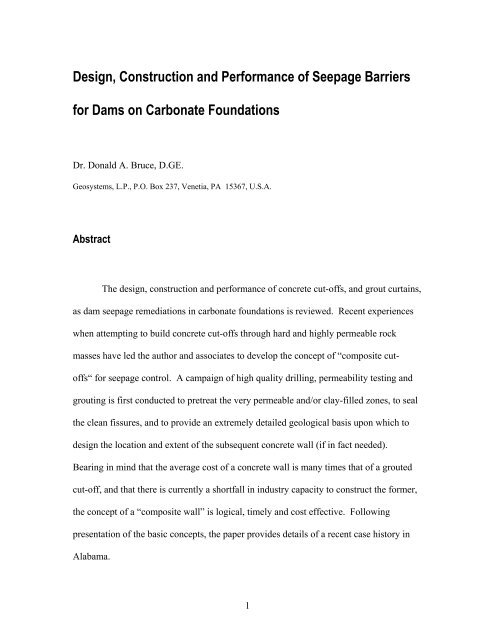
Design, Construction and Performance of ... - Geosystems, LP
Design, Construction and Performance of ... - Geosystems, LP
Design, Construction and Performance of ... - Geosystems, LP

You also want an ePaper? Increase the reach of your titles
YUMPU automatically turns print PDFs into web optimized ePapers that Google loves.
<strong>Design</strong>, <strong>Construction</strong> <strong>and</strong> <strong>Performance</strong> <strong>of</strong> Seepage Barriers<br />
for Dams on Carbonate Foundations<br />
Dr. Donald A. Bruce, D.GE.<br />
<strong>Geosystems</strong>, L.P., P.O. Box 237, Venetia, PA 15367, U.S.A.<br />
Abstract<br />
The design, construction <strong>and</strong> performance <strong>of</strong> concrete cut-<strong>of</strong>fs, <strong>and</strong> grout curtains,<br />
as dam seepage remediations in carbonate foundations is reviewed. Recent experiences<br />
when attempting to build concrete cut-<strong>of</strong>fs through hard <strong>and</strong> highly permeable rock<br />
masses have led the author <strong>and</strong> associates to develop the concept <strong>of</strong> “composite cut<strong>of</strong>fs“<br />
for seepage control. A campaign <strong>of</strong> high quality drilling, permeability testing <strong>and</strong><br />
grouting is first conducted to pretreat the very permeable <strong>and</strong>/or clay-filled zones, to seal<br />
the clean fissures, <strong>and</strong> to provide an extremely detailed geological basis upon which to<br />
design the location <strong>and</strong> extent <strong>of</strong> the subsequent concrete wall (if in fact needed).<br />
Bearing in mind that the average cost <strong>of</strong> a concrete wall is many times that <strong>of</strong> a grouted<br />
cut-<strong>of</strong>f, <strong>and</strong> that there is currently a shortfall in industry capacity to construct the former,<br />
the concept <strong>of</strong> a “composite wall” is logical, timely <strong>and</strong> cost effective. Following<br />
presentation <strong>of</strong> the basic concepts, the paper provides details <strong>of</strong> a recent case history in<br />
Alabama.<br />
1
Introduction<br />
As documented by Weaver <strong>and</strong> Bruce (2007), grout curtains have been used in the<br />
U.S. to control seepage in rock masses under <strong>and</strong> around dams <strong>of</strong> all types since the<br />
1890’s. For a variety <strong>of</strong> underst<strong>and</strong>able, if not always laudable reasons, the long-term<br />
performance <strong>of</strong> many <strong>of</strong> these curtains has not been satisfactory, especially in lithologies<br />
containing soluble <strong>and</strong>/or erodible materials. Foundation remediation in such instances<br />
traditionally involved regrouting, <strong>of</strong>ten <strong>of</strong> course, using the same means, methods <strong>and</strong><br />
materials whose defects were the underlying cause <strong>of</strong> the inadequacy in the first place.<br />
Disillusionment on the part <strong>of</strong> owners <strong>and</strong> engineers with the apparent inability <strong>of</strong><br />
these traditional grouting practices to provide a product <strong>of</strong> acceptable efficiency <strong>and</strong><br />
durability led to the chorus <strong>of</strong> “grouting doesn’t work” voices in the industry from the<br />
mid-1970’s onwards. The fact that effective <strong>and</strong> durable grout curtains were being<br />
installed successfully elsewhere in the world, using different perspectives on design,<br />
construction <strong>and</strong> contractor procurement processes, largely escaped the attention <strong>of</strong> the<br />
doubters who, for all their other <strong>and</strong> obvious qualities, exhibited technological<br />
xenophobia.<br />
Partly as a result <strong>of</strong> the anti-grouting lobby, equally in response to indisputable<br />
geological realities <strong>and</strong> challenges <strong>and</strong> building on technical advances in “slurry wall”<br />
techniques, the concept <strong>and</strong> reality <strong>of</strong> “positive cut-<strong>of</strong>fs” became the mantra for major<br />
embankment dam foundation rehabilitation in North America from 1975 onwards. Such<br />
walls, built through <strong>and</strong> under existing dams by either the panel wall technique, or secant<br />
2
large diameter piles, comprise some type <strong>of</strong> concrete, ranging from high strength to<br />
plastic. In contrast to grout curtains, where well over 90% <strong>of</strong> the cut-<strong>of</strong>f is, in fact, the<br />
virgin, in situ rock, these “positive” cut-<strong>of</strong>fs were, in theory, built <strong>of</strong> 100% preengineered<br />
material <strong>of</strong> well-defined properties.<br />
Such “positive” walls are essential to provide long-term cut-<strong>of</strong>f across karstic<br />
features which contain residual, potentially erodible material: such material simply<br />
cannot be grouted with a degree <strong>of</strong> uniformity <strong>and</strong> confidence to assure satisfactory longterm<br />
performance. The list <strong>of</strong> successful projects executed to date in the U.S. is<br />
extremely impressive (Bruce et al., 2006; Bruce 2007), with many having been installed<br />
in carbonate terrains <strong>of</strong> varying degrees <strong>of</strong> karstification. To date almost 7.5 million<br />
square feet <strong>of</strong> concrete cut-<strong>of</strong>f have been installed in 20 projects.<br />
From the mid-1980’s – albeit in Europe (Lombardi 2003) – a new wave <strong>of</strong> dam<br />
grouting concepts began to emerge. Given that most <strong>of</strong> the leading North American<br />
practitioners had close corporate <strong>and</strong>/or pr<strong>of</strong>essional <strong>and</strong> personal links with this<br />
insurgency, it is not surprising that their heret<strong>of</strong>ore moribund industry began to change.<br />
By the time <strong>of</strong> the seminal 2003 ASCE grouting conference in New Orleans, the<br />
revolution in North American practice for dam foundation grouting had been clearly<br />
demonstrated (Wilson <strong>and</strong> Dreese, 2003; Walz et al., 2003). The concept <strong>of</strong> a<br />
Quantitatively Engineered Grout Curtain was affirmed. Differences in opinion <strong>and</strong><br />
philosophies with the great European practitioners such as Lombardi, the architect <strong>of</strong> the<br />
GIN Method, were not necessarily resolved: they were debated between equals <strong>and</strong> the<br />
respective opinions fairly acknowledged.<br />
3
It is therefore the case that, in North America, there is now expertise <strong>and</strong><br />
experience <strong>of</strong> an unparalleled level in both grout curtains <strong>and</strong> concrete cut-<strong>of</strong>f walls.<br />
This is particularly serendipitous given that the dollar requirement for the application <strong>of</strong><br />
both technologies – in Federal dams alone in the next 5 years – is <strong>of</strong> an order equivalent<br />
to the aggregate <strong>of</strong> the preceding 40 years (Halpin, 2007).<br />
This paper presents a review <strong>of</strong> the current state-<strong>of</strong>-practice in each <strong>of</strong> these two<br />
technologies. The paper describes how these techniques can be combined in the concept<br />
<strong>of</strong> a “composite cut-<strong>of</strong>f” which has potentially extraordinary benefits to owners in the<br />
financial sense, while still assuring the highest verifiable st<strong>and</strong>ards <strong>of</strong> performance <strong>and</strong><br />
durability in the field.<br />
CUT-OFFS<br />
Investigations, <strong>Design</strong>, Specifications <strong>and</strong> Contractor Procurement<br />
• Intensive, focused site investigations are essential as the basis for cut-<strong>of</strong>f design <strong>and</strong><br />
contractor bidding purposes. In particular, these investigations must not only identify<br />
rock mass lithology, structure <strong>and</strong> strength (“rippability”), but also the potential for<br />
loss <strong>of</strong> slurry during panel excavation. This has not always been done, <strong>and</strong> cost <strong>and</strong><br />
schedule have suffered accordingly on certain major projects.<br />
• Special considerations have had to be made when designing cut-<strong>of</strong>fs which must<br />
contact existing concrete structures, or which must be installed in very deep-sided<br />
valley sections, or which must toe in to especially strong rock.<br />
4
• “Test Sections” have proved to be extremely valuable, especially for the contractor to<br />
refine his means, methods <strong>and</strong> quality control systems. Such programs have also<br />
given the dam safety <strong>of</strong>ficials <strong>and</strong> owners the opportunity to gain confidence <strong>and</strong><br />
underst<strong>and</strong>ing in the response <strong>of</strong> their dams to the invasive surgery that constitutes<br />
cut-<strong>of</strong>f wall construction. Furthermore, such programs have occasionally shown that<br />
the foreseen construction method was practically impossible (e.g., a hydromill at<br />
Beaver Dam, AR) or that significant facilitation works (e.g., pregrouting <strong>of</strong> the wall<br />
alignment at Mississinewa Dam, IN, Clearwater Dam, MO, <strong>and</strong> Wolf Creek Dam,<br />
KY) were required.<br />
• Every project has involved a high degree <strong>of</strong> risk <strong>and</strong> complexity <strong>and</strong> has dem<strong>and</strong>ed<br />
superior levels <strong>of</strong> collaboration between designer <strong>and</strong> contractor. This situation has<br />
been best satisfied by procuring a contractor on the basis <strong>of</strong> “best value,” not “low<br />
bid.” This involves the use <strong>of</strong> RFP’s (Requests for Proposals) with a heavy emphasis<br />
on the technical submittal <strong>and</strong>, in particular, on corporate experience, expertise <strong>and</strong><br />
resources, <strong>and</strong> the project-specific Method Statement. These projects are essentially<br />
based on <strong>Performance</strong>, as opposed to Prescriptive Specifications. Partnering<br />
arrangements (which are post-contract) have proved very useful to both parties when<br />
entered into with confidence, enthusiasm, <strong>and</strong> trust.<br />
<strong>Construction</strong> <strong>and</strong> QA/QC<br />
• The specialty contractors have developed a wide <strong>and</strong> responsive variety <strong>of</strong> equipment<br />
<strong>and</strong> techniques to assure penetration <strong>and</strong> wall continuity in a wide variety <strong>of</strong> ground<br />
5
conditions. More than one technique, e.g., clamshell followed by hydromill, has<br />
frequently been used on the same project <strong>and</strong> especially where bouldery conditions<br />
have been encountered.<br />
• Cut-<strong>of</strong>fs can be safely constructed with high lake levels, provided that the slurry level<br />
in the trench can be maintained a minimum <strong>of</strong> 3 feet higher. In extreme geological<br />
conditions, this may dem<strong>and</strong> pretreatment <strong>of</strong> the embankment (e.g., Mud Mountain<br />
Dam, WA) or the rock mass (Mississinewa Dam, IN) to guard against massive,<br />
sudden slurry loss.<br />
• For less severe geological conditions, contractors have developed a variety <strong>of</strong><br />
defenses against slurry losses <strong>of</strong> smaller volume <strong>and</strong> rate by providing large slurry<br />
reserves, using flocculating agents, <strong>and</strong> fillers in the slurry, or by limiting the openpanel<br />
width.<br />
• Very tight verticality tolerances are necessary to assure continuity especially in<br />
deeper cut-<strong>of</strong>fs. Such tolerances have been not only difficult to satisfy, but also<br />
difficult to measure accurately (to ≤ 0.5% <strong>of</strong> wall depth) <strong>and</strong> verify.<br />
• The deepest panel walls have been installed at Wells Dam, WA (223 feet, clamshell)<br />
<strong>and</strong> at Mud Mountain Dam, WA (402 feet, hydromill). The hydromill has proved to<br />
be the method <strong>of</strong> choice for large cut-<strong>of</strong>fs in fill, alluvial soils <strong>and</strong> in rock masses <strong>of</strong><br />
unconfined compressive strengths less than 10,000 psi (massive) to 20,000 psi (fissile,<br />
<strong>and</strong> therefore, rippable).<br />
• Secant pile cut-<strong>of</strong>fs are expensive <strong>and</strong> intricate to build. However, they are the only<br />
option in certain conditions (e.g., heavily karstified, but otherwise hard limestone<br />
rock masses) which would otherwise defeat the hydromill. The deepest such wall<br />
6
(albeit a composite pile/panel wall) was the first — at Wolf Creek, KY in 1975 —<br />
which reached a maximum <strong>of</strong> 280 feet. The most recent pure secant pile wall in<br />
carbonate terrain was at Beaver Dam, AR, 1992-1994.<br />
• A wide range <strong>of</strong> backfill materials has been used, ranging from low strength plastic<br />
concrete, to conventional high strength concrete.<br />
• The preparation <strong>and</strong> maintenance <strong>of</strong> a stable <strong>and</strong> durable working platform has<br />
proved always to be a beneficial investment, <strong>and</strong> its value should not be<br />
underestimated.<br />
• The highest st<strong>and</strong>ards <strong>of</strong> real time QA/QC <strong>and</strong> verification are essential to specify<br />
<strong>and</strong> implement. This applies to every phase <strong>of</strong> the excavation process, <strong>and</strong> to each <strong>of</strong><br />
the materials employed.<br />
• Enhancements have progressively been made in cut-<strong>of</strong>f excavation technology,<br />
especially to raise productivity (particularly in difficult conditions), to increase<br />
mechanical reliability, <strong>and</strong> to improve the practicality <strong>and</strong> accuracy <strong>of</strong> deviation<br />
control <strong>and</strong> measurement.<br />
Potential <strong>Construction</strong> Issues with Cut-Offs<br />
Satisfactory construction <strong>of</strong> positive cut-<strong>of</strong>f walls requires experience, skill, <strong>and</strong><br />
dedication to quality in every aspect <strong>of</strong> the construction process including site preparation,<br />
excavation, trench or hole cleaning, concrete mixing, <strong>and</strong> concrete backfilling. Providing<br />
a positive cut-<strong>of</strong>f requires that the elements <strong>of</strong> the wall are continuous <strong>and</strong> interconnected.<br />
7
The following issues are possible concerns that must be taken into account in wall<br />
construction to prevent defects.<br />
• Element deviation – Misalignment <strong>of</strong> the equipment or inability to control the<br />
excavation equipment can result in deviation <strong>of</strong> elements <strong>and</strong> result in a gap in the<br />
completed wall.<br />
• Uncontrolled Slurry Loss – Cut-<strong>of</strong>f walls through existing water retaining structures<br />
are almost always built to address seepage issues. Although bentonite slurries are<br />
proven in creating a filter cake in soils, the ability <strong>of</strong> bentonite slurries to form a filter<br />
cake in rock fractures is limited. As a general rule <strong>of</strong> thumb, if water is lost during<br />
exploration, one should assume that slurry losses in rock will occur. If the rock is<br />
sufficiently pervious, uncontrollable complete slurry loss can occur. Slurry losses in<br />
embankments have also occurred on past projects due to hydr<strong>of</strong>racturing <strong>of</strong> weak<br />
zones. This is a particularly sensitive issue when excavating through epikarstic<br />
horizons, <strong>and</strong> major karstic features lower in the formation.<br />
• Trench Stability – The factors <strong>of</strong> safety <strong>of</strong> slurry supported excavations in soil are not<br />
high. Movement <strong>of</strong> wedges into the trench or “squeeze in” <strong>of</strong> s<strong>of</strong>t zones can occur.<br />
• Concrete Segregation – Mix design <strong>and</strong> construction practices during backfill are<br />
critical to prevent segregation or honeycombing within the completed wall.<br />
• Soil or Slurry Inclusions – The occurrence <strong>of</strong> soil or slurry filled defects or inclusions<br />
in completed walls are a known issue. If small or discontinuous, these defects are not<br />
critical, but they are very significant if they fully penetrate the width <strong>of</strong> the wall.<br />
8
• Panel Joint Cleanliness – Imperfections or pervious zones along the joints between<br />
elements is a recognized source <strong>of</strong> leakage through completed walls. Cleaning <strong>of</strong><br />
adjacent completed elements by circulating fresh slurry is necessary to minimize the<br />
contamination <strong>of</strong> joints.<br />
<strong>Performance</strong><br />
Surprisingly little has in fact been published to date describing the actual<br />
efficiency <strong>of</strong> cut-<strong>of</strong>f walls after their installation: most <strong>of</strong> the publications describe design<br />
<strong>and</strong> construction <strong>and</strong> have usually been written soon after construction by the contractors<br />
themselves. The soon to be published research into this matter by the Virginia Tech team<br />
<strong>of</strong> Rice <strong>and</strong> Duncan is, therefore, eagerly awaited. Although there is some published<br />
evidence (e.g., Davidson, 1990) that the walls have not always functioned as well as<br />
anticipated, it can be reasonably assumed that the majority <strong>of</strong> the remediations have been<br />
successful, provided a) the wall has been extended laterally <strong>and</strong> vertically into competent,<br />
impermeable <strong>and</strong> non-erodible bedrock; b) that there is full lateral continuity between<br />
panels with no clay contamination; <strong>and</strong> c) that the panels themselves contain no concrete<br />
segregations or slurry/soil inclusions. It may also be stated that the capabilities <strong>of</strong> the<br />
technology <strong>of</strong> the day have not always been able to satisfy the depth criterion. EM 1110-<br />
2-1901 published in 1986 by the USACE states that the experienced efficiency <strong>of</strong> cut-<strong>of</strong>f<br />
walls calculated based on head reduction across the wall was 90% or better for properly<br />
constructed walls.<br />
9
There is also the case <strong>of</strong> the diaphragm wall at Wolf Creek Dam, KY, the length<br />
<strong>and</strong> depth <strong>of</strong> which were restricted by the technology <strong>and</strong> funds available at the time. As<br />
a result, a new wall, deeper <strong>and</strong> larger, is about to be built to finally cut <strong>of</strong>f the flow<br />
occurring through the deep, heavily karstified limestones.<br />
GROUT CURTAINS<br />
<strong>Design</strong><br />
• <strong>Design</strong>ing grout curtains based on rules <strong>of</strong> thumb without consideration <strong>of</strong> the site<br />
geology is no longer an acceptable practice or st<strong>and</strong>ard <strong>of</strong> care. Contemporary<br />
approaches are based on the concept <strong>of</strong> a Quantitatively Engineered Grout Curtain<br />
(QEGC), which provides criteria for the maximum acceptable residual permeability<br />
<strong>and</strong> minimum acceptable dimensions <strong>of</strong> the cut-<strong>of</strong>f (Wilson <strong>and</strong> Dreese, 1998, 2003).<br />
• Prerequisite geological investigations <strong>and</strong> other work required to perform this<br />
quantitative design include:<br />
- Thorough geologic investigations identifying structure, stratigraphy, weathering,<br />
<strong>and</strong> hydraulic conductivity <strong>of</strong> the foundation rock.<br />
- Establishment <strong>of</strong> project performance requirements in terms <strong>of</strong> seepage quantities<br />
<strong>and</strong> seepage pressures. <strong>Design</strong> requirements should consider dam safety, cost,<br />
<strong>and</strong> political acceptability or public perception as they relate to residual seepage.<br />
- Seepage analyses to determine the need for grouting, the horizontal <strong>and</strong> vertical<br />
limits <strong>of</strong> the cut-<strong>of</strong>f, the width <strong>of</strong> the curtain, <strong>and</strong> the location <strong>of</strong> the curtain.<br />
10
- Where relevant, the value <strong>of</strong> the lost water should be compared to the cost <strong>of</strong><br />
more intensive grouting in a cost benefit analysis.<br />
- Specifications written to require best practice for field execution <strong>of</strong> every element<br />
<strong>of</strong> the work.<br />
• Quantitative design <strong>of</strong> grouting requires that the curtain be treated in seepage analyses<br />
as an engineered element. The specific geometry <strong>of</strong> the curtain in terms <strong>of</strong> depth <strong>and</strong><br />
width must be included in the model <strong>and</strong> the achievable hydraulic conductivity <strong>of</strong> the<br />
curtain must also be assumed. Guidance on assigning grout curtain design parameters<br />
<strong>and</strong> performing seepage analyses for grout curtains is covered in detail by Wilson <strong>and</strong><br />
Dreese (2003). More substantial <strong>and</strong> complete guidance on flow modeling <strong>of</strong> grouted<br />
cut-<strong>of</strong>fs is included in the update to USACE EM 1110-2-3506 issued in 2008.<br />
<strong>Construction</strong><br />
Many aspects <strong>of</strong> the construction <strong>of</strong> QEGC’s have also changed greatly in the last<br />
10 years or so, driven by the goals <strong>of</strong> achieving improved operational speed <strong>and</strong><br />
efficiency, satisfying lower residual permeability targets, enhancing QA/QC, verification<br />
<strong>and</strong> real-time control, <strong>and</strong> assuring long-term durability <strong>and</strong> effectiveness. Particularly<br />
important advances are as follows:<br />
• The traditional concepts <strong>of</strong> stage grouting (i.e., up — or down — depending on the<br />
stability <strong>and</strong> permeability <strong>of</strong> the rock mass) <strong>and</strong> closure (i.e., Primary-Secondary-<br />
11
Tertiary Phases) still apply. However, construction in two critical rows, with the<br />
holes in each inclined in opposite directions, has become st<strong>and</strong>ard practice.<br />
• Balanced, multicomponent cement-based grouts are used, to provide high<br />
performance mixes which will have superior stability, rheological <strong>and</strong> durability<br />
properties. The use <strong>of</strong> “neat” cement grouts with high water:cement ratios <strong>and</strong><br />
perhaps nominal amounts <strong>of</strong> superplasticizer or bentonite is simply not acceptable<br />
(Chuaqui <strong>and</strong> Bruce, 2003).<br />
• The current state <strong>of</strong> the art in grouting monitoring <strong>and</strong> evaluation is a fully integrated<br />
system where all field instruments are monitored in real time through a computer<br />
interface, all necessary calculations are performed automatically, grouting quantity<br />
information is tabulated <strong>and</strong> summarized electronically, program analyses are<br />
conducted automatically by the system using numerous variables, <strong>and</strong> multiple,<br />
custom as-built grouting pr<strong>of</strong>iles are automatically generated <strong>and</strong> maintained realtime.<br />
This level <strong>of</strong> technology provides the most reliable <strong>and</strong> high quality project<br />
records with minimal operator effort. In fact, the advent <strong>of</strong> such technology has been<br />
found to substantially decrease grouting program costs while providing<br />
unprecedented levels <strong>of</strong> assurance that the design goal is being met (Dreese, et al.,<br />
2003).<br />
• Modern drilling recording instruments <strong>and</strong> borehole imaging technology allow for<br />
better underst<strong>and</strong>ing <strong>of</strong> subsurface conditions than was previously possible.<br />
Measurement While Drilling (“MWD”) instrumentation provides additional<br />
information during the drilling <strong>of</strong> every hole on a grouting project (Bruce <strong>and</strong> Davis,<br />
2005). Specific energy <strong>and</strong> other recorded data can be evaluated <strong>and</strong> compared to the<br />
12
grouting data to procure as much information as possible from every hole drilled.<br />
Each hole on a grouting project is thereby treated as an exploration hole <strong>and</strong> the data<br />
gathered are utilized to increase the underst<strong>and</strong>ing <strong>of</strong> subsurface conditions. After a<br />
hole has been drilled, borehole imaging can be performed to obtain a “virtual core.”<br />
This equipment is especially useful on destructively drilled production holes where<br />
recovered core is not available for viewing <strong>and</strong> logging, <strong>and</strong> provides invaluable data<br />
such as measurements <strong>of</strong> fracture apertures <strong>and</strong> bedrock discontinuity geometry.<br />
These are then utilized in designing or modifying the grout methods <strong>and</strong> materials.<br />
Borehole images are mapped by qualified personnel <strong>and</strong> the data may be further<br />
analyzed using stereonet analyses.<br />
VERIFICATION AND PERFORMANCE<br />
• Successfully achieving project closure is a three-step process: achieving closure on<br />
individual stages <strong>and</strong> holes; achieving closure on individual lines; <strong>and</strong> achieving<br />
closure on the entire curtain. Proper closure on individual stages <strong>and</strong> holes is<br />
primarily a function <strong>of</strong> the following items: drilling a properly flushed hole, effective<br />
washing <strong>of</strong> the hole, underst<strong>and</strong>ing the geology <strong>of</strong> the stages being grouted; applying<br />
that knowledge along with the results <strong>of</strong> water pressure testing to determine<br />
technically effective <strong>and</strong> cost effective stage selection; selecting appropriate starting<br />
mixes; real-time monitoring <strong>of</strong> the grouting <strong>and</strong> assessing its dynamic behavior in<br />
terms <strong>of</strong> characteristic signatures; making good <strong>and</strong> informed decisions regarding<br />
when to change grout mixes during injection within a stage; <strong>and</strong> managing the hole to<br />
13
completion (i.e., refusal to further grout injection) within a reasonable amount <strong>of</strong><br />
time. The key is to gradually reduce the Apparent Lugeon Value <strong>of</strong> the stage (i.e., the<br />
Lugeon value calculated using grout as the test fluid, <strong>and</strong> taking into account the<br />
apparent viscosity <strong>of</strong> the grout relative to water) to practically zero.<br />
• Pumping large quantities <strong>of</strong> grout for an extended period <strong>of</strong> time without any<br />
indication <strong>of</strong> achieving refusal is generally a waste <strong>of</strong> time <strong>and</strong> grout. Unless a large<br />
cavity has been encountered, the grout being used in this case has a cohesion that is<br />
too low <strong>and</strong> is simply traveling a great distance through a single fracture. Mix<br />
changes need to be managed properly for economy <strong>and</strong> value, especially in karstified<br />
conditions.<br />
• Each line <strong>of</strong> a grout curtain <strong>and</strong> the completed curtain where multiple lines are<br />
installed should be analyzed in detail. Each section <strong>of</strong> the grout curtain should be<br />
evaluated <strong>and</strong> closure plots <strong>of</strong> pre-grouting permeability for each series in the section<br />
plotted. As grouting progresses, the plots should show a continual decrease in pregrouting<br />
permeability for each successive series <strong>of</strong> holes. For example, the results for<br />
the exploration holes <strong>and</strong> primary holes from the first line within a section represent<br />
the “natural permeability” <strong>of</strong> the formation. Secondary holes on each line should<br />
show a progressively reduced permeability compared to the primary holes due to the<br />
permeability reduction associated with grouting <strong>of</strong> the Primaries. Similarly, the pregrouting<br />
permeability <strong>of</strong> tertiary holes should show a marked decline relative to the<br />
secondary holes.<br />
14
• In addition to performing the analyses described above, it is also necessary to review<br />
pr<strong>of</strong>iles indicating the geology, water testing, <strong>and</strong> grouting results. Review <strong>of</strong> the<br />
pr<strong>of</strong>iles with the water Lugeon values displayed on each zone or stage allows for<br />
confirmation that the formation behavior is consistent with the grouting, <strong>and</strong> permits<br />
rapid evaluation <strong>of</strong> any trends or problem areas requiring additional attention. In<br />
addition, this review permits identification <strong>of</strong> specific holes or zones within a hole<br />
that behaved abnormally <strong>and</strong> which are adversely skewing the results <strong>of</strong> the closure<br />
analysis. For example, the average pre-grouting permeability <strong>of</strong> tertiary holes that<br />
appear on a closure analysis plot may be 10 Lugeons, but that average may be caused<br />
by one tertiary hole that had an extraordinarily high value.<br />
• Review <strong>of</strong> the grout line pr<strong>of</strong>iles with the grout takes displayed is also necessary<br />
along with comparison <strong>of</strong> the average grout takes compared to the average Lugeon<br />
values reported by the closure analysis. Areas <strong>of</strong> abnormally high or low grout takes<br />
in comparison to the Lugeon values should be identified for further analysis. The<br />
grouting records for these abnormal zones should be reviewed carefully along with<br />
the pressure testing <strong>and</strong> grouting records from adjacent holes.<br />
“COMPOSITE” CUT-OFFS<br />
Basic Premise<br />
In recent years, there have been a number <strong>of</strong> projects, both completed <strong>and</strong> in<br />
planning, which have featured the construction <strong>of</strong> a concrete cut-<strong>of</strong>f wall installed<br />
15
through the dam <strong>and</strong> into karstified carbonate bedrock. The basic premise <strong>of</strong> such a<br />
“positive” cut-<strong>of</strong>f is clear <strong>and</strong> logical: the presence <strong>of</strong> large clay-filled solution features in<br />
the bedrock will defeat the ability <strong>of</strong> a grout curtain – even when designed <strong>and</strong> built using<br />
best contemporary practices – to provide a cut-<strong>of</strong>f <strong>of</strong> acceptable efficiency <strong>and</strong> durability.<br />
This is particularly important when permanent “walk-away” solutions are required which<br />
must be robust, reliable <strong>and</strong> durable. There is no question that rock fissure grouting<br />
techniques are incompatible with satisfying that goal in the presence <strong>of</strong> substantial clayey<br />
infill materials. However, the benefits <strong>of</strong> a concrete cut-<strong>of</strong>f come at a substantial<br />
premium over those provided by a grout curtain. A typical industry average cost for a<br />
grouted cut-<strong>of</strong>f is <strong>of</strong> the order <strong>of</strong> $25-$50 per square foot. The cost <strong>of</strong> a concrete cut-<strong>of</strong>f<br />
is anywhere from 4 to 10 times this figure, depending on the technique (i.e., panel or<br />
secant), the ground conditions, the depth <strong>of</strong> the cut-<strong>of</strong>f, <strong>and</strong> the nature <strong>of</strong> the site logistics.<br />
Furthermore, the construction <strong>of</strong> a concrete cut-<strong>of</strong>f wall through the typical karstified<br />
limestone or dolomite rock mass will involve the excavation <strong>of</strong> the rock (which in the<br />
main part will be in fact very hard, impermeable, <strong>and</strong> competent with UCS values in<br />
excess <strong>of</strong> 20,000 psi) <strong>and</strong> backfilling that thin excavation with a material <strong>of</strong> strength<br />
4,000 psi or less. In effect, great effort <strong>and</strong> expense is expended to provide a membrane<br />
(through the greater part <strong>of</strong> the project) which is <strong>of</strong> lower strength than the rock mass<br />
excavated to construct it.<br />
Another practical factor that has <strong>of</strong>ten been overlooked historically is that<br />
construction <strong>of</strong> a concrete wall may simply not be feasible in ground conditions which<br />
permit the panel trench stabilizing medium (i.e., bentonite slurry) or the drill flush (air or<br />
water) to be lost into the formation: in extremis either <strong>of</strong> these phenomena could create a<br />
16
dam safety threat, let alone the loss <strong>of</strong> very expensive excavation or drilling equipment at<br />
depth. The solution, not surprisingly, in such situations has been to suspend the wall<br />
construction <strong>and</strong> to systematically <strong>and</strong> intensively pretreat the formation by grouting.<br />
In doing so, however, it has not been always the case that the designer <strong>of</strong> the wall has<br />
appreciated that, in addition to this campaign <strong>of</strong> drilling, water pressure testing <strong>and</strong><br />
grouting constituting a facilitating improvement to the rock mass, such work also<br />
generates a most detailed site investigation – at very close centers – <strong>of</strong> the whole extent<br />
<strong>of</strong> the originally foreseen concrete cut-<strong>of</strong>f area. It would be reasonable, therefore, to<br />
propose that the data from these pretreatment programs could be used to review the true<br />
required extent <strong>of</strong> the subsequent concrete wall, <strong>and</strong> thereby reduce overall project costs<br />
with sound engineering justification.<br />
The concept may then be taken a stage further. Instead <strong>of</strong> drilling <strong>and</strong> grouting<br />
being conducted only as a remedial/facilitating operation under emergency conditions,<br />
specify it, as an originally foreseen designed concept to:<br />
• allow the location <strong>and</strong> extent <strong>of</strong> the major karstic features, which actually require cut<strong>of</strong>f<br />
with a concrete wall, to be precisely identified;<br />
• pretreat the ground, <strong>and</strong> especially the epikarst, to an intensity that bentonite slurry or<br />
drill flush will not be lost during the concrete wall construction. A typical criterion is<br />
10 Lugeons;<br />
• grout, to a verified engineered st<strong>and</strong>ard, the rock mass around <strong>and</strong> under the karstic<br />
features <strong>and</strong> which does not contain erodible material in its fissures. A typical<br />
criterion is in the range 1-3 Lugeons.<br />
17
By embracing these precepts, it is therefore logical to propose the concept <strong>of</strong> a<br />
“composite cut-<strong>of</strong>f”: an expensive concrete wall where actually required for long-term<br />
performance certitude, plus a contiguous <strong>and</strong> enveloping grout curtain to provide<br />
acceptable levels <strong>of</strong> impermeability <strong>and</strong> durability in those portions <strong>of</strong> the rock mass with<br />
minimal erodible fissure infill material.<br />
Illustrative Examples<br />
With one eye on the immediate future requirements <strong>of</strong> seepage remediation<br />
involving cut-<strong>of</strong>fs under dams, it may be stated that karst is either stratigraphically driven,<br />
or structurally related. Figure 1 a) shows a case where the major horizon <strong>of</strong> long-term<br />
seepage <strong>and</strong> erosion concern is limited to the 30 feet or so <strong>of</strong> epikarst; Figure 1 b) is the<br />
case where the seepage <strong>and</strong> erosion concern is in a particular deep stratigraphic member;<br />
<strong>and</strong> Figure 1 c) shows the condition where the karstification has developed along discrete<br />
structural discontinuities. (This is the case illustrated in the subsequent case history <strong>of</strong><br />
Bear Creek Dam, AL.) For the sake <strong>of</strong> argument, assume that the cut-<strong>of</strong>f has to be 1,000<br />
feet long, the cost <strong>of</strong> drilling <strong>and</strong> grouting is $30 per square foot, the concrete wall costs<br />
$120 per square foot <strong>and</strong> the maximum vertical extent <strong>of</strong> the cut-<strong>of</strong>f is 110 feet (a<br />
massive shale aquiclude exists at 100 feet). The dam itself is “invisible” in this exercise.<br />
For the configuration <strong>of</strong> Figure 1 a), the original design features a concrete cut-<strong>of</strong>f<br />
wall extending 10 feet into the aquiclude. The cost would therefore be 1,000 feet x 110<br />
feet x $120 = $13.2 million. (This would, however, assume that construction <strong>of</strong> the wall<br />
through the epikarst would be feasible without pretreatment.) Alternatively, if the entire<br />
18
alignment were to be pregrouted, it would be revealed that there was no need to construct<br />
the wall deeper than, say 35 feet. The total cost <strong>of</strong> this composite wall would therefore<br />
be:<br />
Drill <strong>and</strong> Grout: 1,000 feet x 110 feet x $30/sft. =<br />
Plus Wall: 1,000 feet x 35 feet x $120/sft. =<br />
$3.3 million<br />
$4.2 million<br />
$7.5 million<br />
Figure 1 a). Epikarst is found during pregrouting to an average <strong>of</strong> 30 feet b.g.s. The<br />
concrete cut-<strong>of</strong>f needs only to be installed to 35 feet b.g.s.<br />
Figure 1 b). Heavily karstified horizons are found at depth. Therefore the concrete cut-<strong>of</strong>f is<br />
required for the full extent. The grouting has pretreated the karstic horizons to permit safe concrete<br />
cut-<strong>of</strong>f construction.<br />
Figure 1 c). Discrete karstic features exist, related to major structural features.<br />
Thus, individual concrete cut-<strong>of</strong>fs can be installed, after drilling <strong>and</strong> grouting<br />
have confirmed the extent <strong>of</strong> these features <strong>and</strong> have pretreated them to permit<br />
safe concrete cut-<strong>of</strong>f construction.<br />
• For configuration 1 b), the cost <strong>of</strong> the predrilling <strong>and</strong> grouting would be the same, i.e.,<br />
$3.3 million. However, in this case, the concrete wall would have to be $13.2 million.<br />
19
The overall cost <strong>of</strong> the cut-<strong>of</strong>f would therefore be $16.5 million. However, the<br />
pretreatment in advance <strong>of</strong> the concrete wall would assure that the wall could in fact<br />
be built in a cost-effective <strong>and</strong> timely fashion, i.e., without interruptions caused by<br />
massive slurry loss. The overall (high) project cost would simply be a reflection <strong>of</strong> a<br />
uniquely challenging geological situation, i.e., a continuous bed <strong>of</strong> erodible material<br />
at depth.<br />
• For configuration 1 c), the pretreatment would again cost $3.3 million. It would<br />
result in the identification <strong>of</strong> three discrete zones <strong>of</strong> structurally defined karst <strong>of</strong><br />
combined area 3 x 80 feet x 40 feet = 9,600 sq ft. Therefore, the cost <strong>of</strong> the concrete<br />
wall actually needed to cut these features <strong>of</strong>f would be 9,600 sq ft. x $120/sq ft. =<br />
$1,152,000. Thus, the total cost <strong>of</strong> the composite wall is $3,300,000 + $1,152,000 =<br />
$4.5 million.<br />
Thus, the investment in the predrilling <strong>and</strong> grouting program generates very large savings<br />
in cases a) <strong>and</strong> c), whereas for case b) it assures that the wall, which must be built, can be<br />
built without massive delays, difficulties, or – at worst – creating dam safety issues.<br />
20
Recommendations for Grouting for a “Composite Wall”<br />
Site Investigation <strong>and</strong> Assessment <strong>and</strong> <strong>Design</strong><br />
• Research <strong>and</strong> utilize all the historical data (including original construction<br />
photographs) which may have bearing on the development <strong>of</strong> a tentative geostructural<br />
model. An excellent example is provided by Spencer (2006).<br />
• Conduct a new, thoughtful <strong>and</strong> focused site investigation to test the tentative<br />
geostructural model <strong>and</strong> provide prospective bidders with the kinds <strong>of</strong> information<br />
they truly need to estimate productivity <strong>and</strong> to quantify other construction risks.<br />
• Develop an initial estimate <strong>of</strong> the extent <strong>of</strong> the composite cut-<strong>of</strong>f <strong>and</strong> its respective<br />
components, i.e., concrete wall <strong>and</strong> grout curtain.<br />
• Assess the adequacy <strong>of</strong> the existing dam <strong>and</strong> foundation instrumentation, <strong>and</strong> design<br />
<strong>and</strong> install additional monitoring arrays as appropriate. Revise the reading frequency<br />
protocols as appropriate.<br />
Preparation <strong>of</strong> Contract Documents <strong>and</strong> Contractor Procurement Methods<br />
• Create a <strong>Performance</strong> (as opposed to Prescriptive) Specification, while at the same<br />
time clearly defining what methods <strong>and</strong> techniques are not acceptable. <strong>Performance</strong><br />
goals must be explicitly defined, together with their means <strong>of</strong> verification.<br />
• Procure the specialty contractor on the “Best Value” basis, not “Low Bid”.<br />
21
• M<strong>and</strong>ate “Partnering” as a minimum; favor “Alliancing” as the goal (Carter <strong>and</strong><br />
Bruce, 2005).<br />
• Perhaps separate general construction activities (e.g., <strong>of</strong>fice modifications, service<br />
relocation) into a different contract, but always leave the design <strong>and</strong> construction <strong>of</strong><br />
the working platform to the specialist contractor.<br />
Technical Aspects<br />
• If flush water has been lost during investigatory drilling, slurry will certainly be lost<br />
during wall excavation, without pretreatment in those same areas.<br />
• The minimum treatment intensity will feature two rows <strong>of</strong> inclined holes, one either<br />
side <strong>of</strong> the subsequent wall location. The rows may be 5 to 10 feet apart, <strong>and</strong> the<br />
holes in each row will typically close at 5- to 10-foot centers. The inclination<br />
(typically 15º <strong>of</strong>f vertical) will be different in each row.<br />
• The curtain should be installed to at least 50 feet below <strong>and</strong> beyond the originally<br />
foreseen extent <strong>of</strong> the cut-<strong>of</strong>f to assure adequate coverage <strong>and</strong> to search for<br />
unanticipated problems. The treatment must be regarded as an investigatory tool<br />
equally as much as a ground pretreatment operation <strong>and</strong> as a sealing <strong>of</strong> clean rock<br />
fissures.<br />
• “Measurement While Drilling” principles are to be used; the philosophy being that<br />
every hole drilled in the formation (not just cored investigations) is a source <strong>of</strong><br />
valuable geotechnical information.<br />
22
• Special attention must be paid to the epikarstic horizon, which will typically require<br />
special grouting methods such as MPSP (Multiple Packer Sleeve Pipe) (Bruce <strong>and</strong><br />
Gallavresi, 1988) descending stages, <strong>and</strong> special grout mixes.<br />
• A test section at least 100 feet long should be conducted <strong>and</strong> verified to allow<br />
finalization <strong>of</strong> the Method Statement for the balance <strong>of</strong> the grouting work. A residual<br />
permeability <strong>of</strong> 10 Lugeons or less should be sought in the area which is later to<br />
accept the cut-<strong>of</strong>f, <strong>and</strong> lower in elevations below the future cut-<strong>of</strong>f toe. Conversely, a<br />
falling head test in vertical verification holes, using bentonite slurry, is an appropriate<br />
test. Verification holes should be cored, <strong>and</strong> observed in situ with a televiewer to<br />
demonstrate the thoroughness <strong>of</strong> the grouting.<br />
• In terms <strong>of</strong> the details <strong>of</strong> execution, the principles previously detailed to create<br />
Quantitatively Engineered Grout Curtains should be adopted. Thus, one can<br />
anticipate stage water tests; balanced, modified, stable grouts; <strong>and</strong> computer<br />
collection, analysis <strong>and</strong> display <strong>of</strong> injection data. When drilling the verification holes<br />
(at 25- to 100-foot centers between the two grout rows), particular care must be taken<br />
to assure that no drill rods are ab<strong>and</strong>oned within the alignment <strong>of</strong> the wall since this<br />
steel will adversely impact subsequent wall excavation techniques.<br />
• Grouting pressures at refusal should be at least twice the foreseen maximum slurry<br />
pressure exerted during panel construction.<br />
23
<strong>Construction</strong><br />
• The work must be conducted in accordance with the Contractor’s detailed Method<br />
Statement which, in turn, must be in compliance with the minimum requirements <strong>of</strong><br />
the Specification unless otherwise modified during the bidding <strong>and</strong> negotiation<br />
process. At the same time, modifications to the foreseen means <strong>and</strong> methods can be<br />
anticipated on every project, in response to unanticipated phenomena. Prompt<br />
attention to, <strong>and</strong> resolution <strong>of</strong>, these challenges are essential.<br />
• As noted above, special attention is merited to the details <strong>of</strong> the design <strong>and</strong><br />
construction <strong>of</strong> the working platform. The Contractor’s site support facilities (e.g.,<br />
workshop, slurry storage <strong>and</strong> cleaning, concrete operations) can be completed <strong>and</strong> the<br />
utilities extended along the alignment (water, air, light, slurry) during the building <strong>of</strong><br />
the work platform.<br />
• The Test Section should be established in a structurally non-critical area, which does<br />
not contain the deepest extent <strong>of</strong> the foreseen concrete wall. The Test Section can,<br />
however, be integrated into the final works if it is proved to have acceptable quality.<br />
• The concrete wall excavation equipment must have adequate redundancy, <strong>and</strong> must<br />
be supported by appropriate repair/maintenance facilities. A variety <strong>of</strong> equipment is<br />
usually necessary (clamshell, hydromill, chisels, backhoe) to best respond to variable<br />
site conditions <strong>and</strong> construction sequences. St<strong>and</strong>ard mechanical features, such as the<br />
aut<strong>of</strong>eed facility on hydromills, must not be disabled in an attempt to enhance<br />
productivity.<br />
24
• The site laboratory must be capable <strong>of</strong> conducting accurately <strong>and</strong> quickly the whole<br />
range <strong>of</strong> tests required. In addition, the Contractor’s Technical/Quality Manager, who<br />
is a vital component in any such project, must be fully conversant with all the<br />
principles <strong>and</strong> details involved in the monitoring <strong>of</strong> the construction, <strong>and</strong> <strong>of</strong> the dam<br />
itself. In particular, expertise with panel or pile verticality <strong>and</strong> continuity<br />
measurement is essential.<br />
• Emergency Response Plans must be established to satisfy any event which may<br />
compromise dam safety.<br />
Assessment <strong>of</strong> Cut-Off Effectiveness<br />
The protocols established for observations <strong>and</strong> instrument readings during<br />
remediation must be extended after remediation although usually at a somewhat reduced<br />
frequency. The data must be studied <strong>and</strong> rationalized in real time so that the remediation<br />
can be verified as meeting the design intent. Alternatively, it may become apparent that<br />
further work is necessary, a requirement that becomes clear only when the impact <strong>of</strong> the<br />
remediation <strong>of</strong> the dam/foundation system is fully understood. Finally, Owners <strong>and</strong><br />
<strong>Design</strong>ers should publish the results <strong>of</strong> these longer-term observations so that their peers<br />
elsewhere can be well briefed prior to engaging in their own programs <strong>of</strong> similar scope<br />
<strong>and</strong> complexity.<br />
25
Case History – Bear Creek Dam, AL<br />
This dam is in the northern part <strong>of</strong> the state <strong>and</strong> was constructed as a 1,385-footlong,<br />
homogeneous embankment in the late 1960’s. It is owned by the Tennessee Valley<br />
Authority (TVA). However, since first filling in 1969, it had experienced significant<br />
seepage through its karstic limestone foundation. Several remedial efforts resulted in<br />
only limited or temporary success <strong>and</strong> the TVA decided to conduct a major rehabilitation,<br />
which eventually featured the construction <strong>of</strong> a downstream, roller-compacted, concrete<br />
(RCC) reinforcement structure built over a new cut-<strong>of</strong>f (Charlton et al., 2010).<br />
The site is underlain by Mississippian Age sediments <strong>of</strong> the Bangor Formation.<br />
In summary, from rock surface to depth, the cross section comprises:<br />
• the upper Bangor Limestone (cherty, crystalline limestone <strong>and</strong> fossilferous<br />
“packstone”);<br />
• the Banger Shale (12-18 feet thick mudstone unit);<br />
• the lower Bangor Limestone (fine, grained oolitic packstone).<br />
The packstone has been found to be very susceptible to solution activity, <strong>and</strong><br />
proved to be the most challenging zone <strong>of</strong> the subsurface with respect to grouting <strong>and</strong><br />
foundation preparation as a result <strong>of</strong> the large solution features <strong>and</strong> weathered zones that<br />
are not present to the same extent in overlying <strong>and</strong> underlying crystalline <strong>and</strong> cherty<br />
limestone layers.<br />
This project was placed on a “fast track” by TVA <strong>and</strong> early conceptual designs<br />
contemplated the construction <strong>of</strong> a secant pile concrete cut-<strong>of</strong>f along the entire alignment,<br />
26
earing in mind the karstic features <strong>and</strong> a historical lack <strong>of</strong> success with “traditional”<br />
grouting methods under the existing dam. In 2007, a very intense site investigation<br />
program was carried out, including 24 core holes, permeability testing, geophysical<br />
borehole logging, surface geophysics <strong>and</strong> groundwater flow analysis. Historical data<br />
from the original dam construction were also integrated <strong>and</strong> a robust geological <strong>and</strong><br />
geostructural model <strong>of</strong> the foundation <strong>of</strong> the new structure was developed.<br />
Based on this model, the nature <strong>of</strong> the foundation treatment was also modified<br />
with the adoption <strong>of</strong> a “composite wall” cut-<strong>of</strong>f. The concept was to install a site-long<br />
grout curtain <strong>and</strong> to later create concrete cut-<strong>of</strong>f panels only in those areas <strong>and</strong> to such<br />
depths as dictated by the presence <strong>of</strong> major karstic features. The precise dimensions <strong>of</strong><br />
these discrete cut-<strong>of</strong>fs would be determined by close evaluation <strong>of</strong> the drilling <strong>and</strong><br />
grouting records, <strong>and</strong> the results <strong>of</strong> careful mapping <strong>of</strong> the exposed rock surface.<br />
The mapping, cleaning <strong>and</strong> surficial treatment <strong>of</strong> the foundation rock was<br />
conducted to an extremely high st<strong>and</strong>ard (Photographs 1, 2, 3 <strong>and</strong> 4), inspected <strong>and</strong><br />
directed by the Engineer <strong>of</strong> Record (P.C. Rizzo Associates Inc.). The foundation<br />
preparation involved the excavation <strong>of</strong> about 40,000 cubic yards <strong>of</strong> residual soil, 25,000<br />
cubic yards <strong>of</strong> alluvium, 6,000 cubic yards <strong>of</strong> fill, <strong>and</strong> 10,000 cubic yards <strong>of</strong> moderately<br />
to intensely weathered rock. Approximately 100 cubic yards <strong>of</strong> existing detritus was<br />
removed from solution cavities, 5,500 cubic yards <strong>of</strong> dental concrete was placed in<br />
surface irregularities <strong>and</strong> an additional 1,200 cubic yards placed to provide more level<br />
working surfaces for drill rigs <strong>and</strong> RCC placement. By integrating all observations <strong>and</strong><br />
investigations, an extremely detailed geostructural map <strong>of</strong> the foundation was developed<br />
which indicated the position <strong>of</strong> the major karstic features striking across the dam’s axis.<br />
27
The two-row grout curtain featured holes drilled 15º <strong>of</strong>f vertical in order to ensure<br />
that vertical joints were intersected (Figure 2). <strong>Construction</strong> began with the coring <strong>of</strong> 34<br />
“superprimaries” to further explore the foundation. These holes were subject to<br />
geophysical logging, optical televiewing <strong>and</strong> multipressure Lugeon testing, prior to<br />
grouting. Thereafter, the intermediate Primaries, Secondaries <strong>and</strong> Tertiaries (where<br />
deemed necessary) were drilled with rotary percussion <strong>and</strong> water flush. A Drilling<br />
Parameter Recorder was used to record the drilling characteristics <strong>of</strong> each hole, thereby<br />
contributing greatly to the pool <strong>of</strong> knowledge on the variability <strong>of</strong> the rock mass, both<br />
laterally <strong>and</strong> vertically.<br />
Photograph 1. Irregular packstone surface detected in seismic refraction survey.<br />
Photograph 2. Weathered zones mapped in Bangor Shale Unit C beneath historic Bear Creek<br />
channel.<br />
Photograph 3. Cherty limestone <strong>and</strong> packstone contact.<br />
Photograph 4. Cleaning <strong>of</strong> N30E features.<br />
28
Figure 2. Example subsurface pr<strong>of</strong>ile. Width <strong>of</strong> pr<strong>of</strong>ile is 35 feet.<br />
Computer controlled, real time data monitoring <strong>and</strong> control <strong>of</strong> all stage water tests<br />
<strong>and</strong> grout injections was m<strong>and</strong>ated, <strong>and</strong> daily updates <strong>of</strong> drawings showing all relevant<br />
geological <strong>and</strong> construction-related data were required. Grouts ranged from a suite <strong>of</strong><br />
balanced, stable, multicomponent High Mobility Grouts (based on Type III cement),<br />
through Medium Mobility Grout (flyash enriched), to Low Mobility Grout, depending on<br />
the conditions encountered. Primary holes extended into the Bangor Shale while the<br />
depths <strong>of</strong> higher order holes were generally based on interpretation <strong>of</strong> all available<br />
information.<br />
Cored verification holes, located between the two grout lines, confirmed that the<br />
target residual permeability (a maximum <strong>of</strong> 5 Lugeons) had been reached. Careful<br />
review <strong>of</strong> all data sources thereafter confirmed the presence <strong>and</strong> extent <strong>of</strong> 4 major karstic<br />
features, which required further closure with concrete, as detailed in Table 1 <strong>and</strong> Table 2.<br />
29
Table 1. High mobility grout properties.<br />
PARAMETER<br />
(UNIT)<br />
MIX A MIX B MIX C PURPOSE OF REQUIREMENT<br />
Bleed (%) ≤ 3.0 ≤ 3.0 ≤ 3.0<br />
Pressure Filtration<br />
K pf (min -1/2 )<br />
≤ .040 ≤ .040 ≤ .040<br />
Viscosity (sec) 35 50 – 55 80+<br />
Stiffening Time (hr) ≥ 3 ≥ 3 ≥ 3<br />
Low bleed prevents voids caused<br />
by grout settlement (stability).<br />
Low pressure filtration corresponds<br />
to less mix water being pressed out<br />
<strong>of</strong> the grout, promotes long<br />
distance penetration into fractures.<br />
Provides range <strong>of</strong> viscosities to<br />
adjust as appropriate to subsurface<br />
conditions.<br />
Provide enough time for mix,<br />
injection, travel prior to set.<br />
Table 2. Cut-<strong>of</strong>f panel information.<br />
CUTOFF<br />
PANEL #<br />
STATION<br />
EXTENTS<br />
EXPECTED MAX.<br />
DEPTH (FEET)<br />
GEOLOGIC RATIONALE FOR PANEL<br />
1 8+00 to 8+67 35<br />
Clay infill/void activity at depths 25-<br />
30 feet.<br />
2 7+00 to 7+40 35 Clay infill at depths up to 30 feet.<br />
3 3+10 to 4+77 35<br />
Cut<strong>of</strong>f very weathered zones in the<br />
Bangor Shale at the maximum<br />
section <strong>of</strong> the new structure.<br />
4 2+40 to 2+50 23<br />
Cut<strong>of</strong>f the continuation <strong>of</strong> N32E<br />
sluiceway solution feature, act as test<br />
panel for construction method.<br />
These panels were constructed in the 10-foot-wide gap between the two rows <strong>of</strong><br />
grout holes, using a hoe-ram <strong>and</strong> longreach excavator. This work was conducted by<br />
TVA’s Heavy Equipment Division (which was also responsible for the site preparation<br />
<strong>and</strong> surface treatment). Dewatering issues during panel excavation were minimal.<br />
Completed <strong>and</strong> cured panels were cored <strong>and</strong> water tested to verify their integrity <strong>and</strong><br />
continuity, <strong>and</strong> this phase <strong>of</strong> work was satisfactorily completed in December 2008.<br />
30
The RCC structure has since been completed over the new composite cut-<strong>of</strong>f <strong>and</strong><br />
is now fully functional. The cut-<strong>of</strong>f is performing perfectly satisfactorily <strong>and</strong> as predicted.<br />
Final Remarks<br />
We arrive at an extraordinary <strong>and</strong> unprecedented time in the ongoing story <strong>of</strong><br />
major dam rehabilitation in North America. Strengthened by decades <strong>of</strong> outst<strong>and</strong>ing but<br />
hard won success <strong>and</strong> continuous technological developments, contractors who specialize<br />
in constructing concrete cut-<strong>of</strong>fs through <strong>and</strong> under operational dams have now<br />
unprecedented expertise to <strong>of</strong>fer to an industry craving their skills <strong>and</strong> resources.<br />
Grouting specialists – both contractors <strong>and</strong> consultants – have emerged to bring to the<br />
North American market a unique perspective <strong>and</strong> feeling for their work that is<br />
unparalleled historically <strong>and</strong> geographically. It is time to squash the false debate <strong>of</strong><br />
“grouting vs. concrete walls.” The obvious way forward is to take the best from each<br />
camp: drill, water test <strong>and</strong> grout (relatively cheaply) to prepare the ground for a concrete<br />
wall whose (relatively expensive) extent is now properly defined. Then, build, in<br />
improved ground conditions, the definitive concrete wall only in those areas where the<br />
grouting cannot be expected to be effective in the long term.<br />
Our dams must be repaired, in a way that can be regarded as “permanent.”<br />
However, there still remains the goal that we should ensure that our designs <strong>and</strong><br />
implementations are cost-effective. Furthermore, there is simply insufficient industrial<br />
capacity in the U.S. to build the foreseen volume <strong>of</strong> cut-<strong>of</strong>fs solely by concrete wall<br />
31
construction techniques in the time frame available. The concept <strong>of</strong> the “composite cut<strong>of</strong>f”<br />
is therefore logical, timely <strong>and</strong> the obvious choice.<br />
Disclaimer <strong>and</strong> Acknowledgements<br />
TVA gave permission for publishing the details <strong>of</strong> the Bear Creek project, but<br />
does not endorse any entity or firm associated with this work. The author wishes to<br />
acknowledge the exceptional efforts <strong>of</strong> John Charlton <strong>and</strong> Conrad Ginther <strong>of</strong> P.C. Rizzo<br />
Associates Inc., the field <strong>and</strong> head <strong>of</strong>fice personnel <strong>of</strong> TVA, <strong>and</strong> the staff <strong>of</strong> GeoCon Inc.<br />
who conducted the drilling <strong>and</strong> grouting. In addition, the “composite wall” concept has<br />
been a joint development involving Trent Dreese <strong>and</strong> David Wilson <strong>of</strong> Gannett Fleming<br />
Inc., <strong>and</strong> Doug Heenan <strong>and</strong> Jim Cockburn <strong>of</strong> Advanced <strong>Construction</strong> Techniques.<br />
References Cited<br />
Bruce, D.A., A. Ressi di Cervia <strong>and</strong> J. Amos-Venti. (2006). “Seepage Remediation by<br />
Positive Cut-Off Walls: A Compendium <strong>and</strong> Analysis <strong>of</strong> North American Case<br />
Histories,” Canadian Dam Association Conference, September 30 – October 5,<br />
Québec City, Québec.<br />
Bruce, D.A., (2007). “Dam Remediation by Anchors <strong>and</strong> Cut-Offs: A Summary <strong>of</strong> Two<br />
National Research Programs,” 38 th Annual Ohio River Valley Soil Seminar,<br />
Louisville, KY, November 14, 35 pp.<br />
Bruce, D.A. <strong>and</strong> J.P. Davis. (2005). “Quality <strong>and</strong> Quantification in Small Hole Drilling,”<br />
Geo3 GEO <strong>Construction</strong> Quality Assurance/Quality Control Conference Proceedings,<br />
32
Editors D.A. Bruce <strong>and</strong> A.W. Cadden, Dallas/Ft. Worth, TX, November 6-9, pp. 271-<br />
282.<br />
Bruce, D.A. <strong>and</strong> F. Gallavresi. (1988). “The MPSP System: A New Method <strong>of</strong> Grouting<br />
Difficult Rock Formations.” ASCE Geotechnical Special Publication No. 14,<br />
“Geotechnical Aspects <strong>of</strong> Karst Terrains.” pp. 97-114. Presented at ASCE National<br />
Convention, Nashville, TN. May 10-11.<br />
Carter, J. <strong>and</strong> D.A. Bruce. (2005). “Enhancing the Quality <strong>of</strong> the Specialty Contractor<br />
Procurement Process: Creating an Alliance,” Geo 3 GEO <strong>Construction</strong> Quality<br />
Assurance/Quality Control Conference Proceedings, Editors D.A. Bruce <strong>and</strong> A.W.<br />
Cadden, Dallas/Ft. Worth, TX, November 6-9, p 76-87.<br />
Charlton, J.E., C.H. Ginther <strong>and</strong> D.A. Bruce. (2010). “Comprehensive Foundation<br />
Rehabilitation at Bear Creek Dam,” Environmental <strong>and</strong> Engineering Geoscience, V.<br />
16, No. 3, August, pp. 211-227.<br />
Chuaqui, M. <strong>and</strong> D.A. Bruce. (2003). “Mix <strong>Design</strong> <strong>and</strong> Quality Control Procedures for<br />
High Mobility Cement Based Grouts.” Grouting <strong>and</strong> Ground Treatment, Proceedings<br />
<strong>of</strong> the Third International Conference, Geotechnical Special Publication No. 120.<br />
Edited by L.F. Johnsen, D.A. Bruce, <strong>and</strong> M.J. Byle, American Society <strong>of</strong> Civil<br />
Engineers, New Orleans, LA, February 10-12, pp. 1153-1168.<br />
Davidson, L. (1990). “<strong>Performance</strong> <strong>of</strong> the Concrete Diaphragm Wall at Navajo Dam,”<br />
10 th Annual USCOLD Conference, New Orleans, LA, March 6-7, 21 p.<br />
Dreese, T., D.B. Wilson, D.M. Heenan, <strong>and</strong> J. Cockburn. (2003) "State <strong>of</strong> the Art in<br />
Computer Monitoring <strong>and</strong> Analysis <strong>of</strong> Grouting," Grouting <strong>and</strong> Ground Treatment,<br />
Proceedings <strong>of</strong> the Conference sponsored by the Geotechnical Engineering Division<br />
33
<strong>of</strong> the American Society <strong>of</strong> Civil Engineers, New Orleans, LA, February 10-12, pp.<br />
1440-1453.<br />
Halpin (2007). “Trends <strong>and</strong> Lessons in Assessing Risks Posed by Flood Damage<br />
Reduction Infrastructure,” ORVSS XXXVIII, Ohio River Valley Soils Seminar,<br />
Louisville, KY, November 14.<br />
Lombardi, G. (2003). “Grouting <strong>of</strong> Rock Masses.” Grouting <strong>and</strong> Ground Treatment,<br />
Proceedings <strong>of</strong> the Third International Conference, Geotechnical Special Publication<br />
No. 120. American Society <strong>of</strong> Civil Engineers, New Orleans, LA, February 10-12,<br />
pp. 164-197.<br />
Walz, A.H., D.B. Wilson, D.A. Bruce, <strong>and</strong> J.A. Hamby. (2003). “Grouted Seepage Cut<strong>of</strong>fs<br />
in Karstic Limestone.” Grouting <strong>and</strong> Ground Treatment, Proceedings <strong>of</strong> the<br />
Third International Conference, Geotechnical Special Publication No. 120. American<br />
Society <strong>of</strong> Civil Engineers, New Orleans, LA, February 10-12, pp. 967-978.<br />
Weaver, K. <strong>and</strong> D.A. Bruce (2007). “Dam Foundation Grouting, Revised <strong>and</strong> Exp<strong>and</strong>ed<br />
Edition,” American Society <strong>of</strong> Civil Engineers, ASCE Press, New York, 504 pp.<br />
Weaver, K.D. <strong>and</strong> D.A. Bruce (2007). “Dam Foundation Grouting, Revised <strong>and</strong><br />
Exp<strong>and</strong>ed Edition,” American Society <strong>of</strong> Civil Engineers, ASCE Press, New York,<br />
504 p.<br />
Wilson, D. <strong>and</strong> T. Dreese (1998) "Grouting Technologies for Dam Foundations,"<br />
Proceedings <strong>of</strong> the 1998 Annual Conference, ASDSO, Las Vegas, Nevada.<br />
Wilson, D. <strong>and</strong> T. Dreese (2003) “Quantitatively Engineered Grout Curtains,” Grouting<br />
<strong>and</strong> Ground Treatment, Proceedings <strong>of</strong> the Conference sponsored by the Geotechnical<br />
34
Engineering Division <strong>of</strong> the American Society <strong>of</strong> Civil Engineers, New Orleans, LA,<br />
February 10-12, pp. 881-892.<br />
USACE (1986) EM 1110-2-1901.<br />
USACE (2008) EM 1110-2-3506.<br />
35