High Capacity Grouted Micropiles - Geosystems, LP
High Capacity Grouted Micropiles - Geosystems, LP
High Capacity Grouted Micropiles - Geosystems, LP

Create successful ePaper yourself
Turn your PDF publications into a flip-book with our unique Google optimized e-Paper software.
<strong>High</strong> <strong>Capacity</strong> <strong>Grouted</strong> <strong>Micropiles</strong>: The State of Practice in the United States<br />
MICROPIEUX INJECTES DE HAUTE CAPACITE: Les Règles de l'Art aux Etats Unis<br />
D.A. BRUCE, <strong>Geosystems</strong>, L.P., Venetia, PA, U.S.A.<br />
I. JURAN, Polytechnic University, Brooklyn, NY, U.S.A.<br />
A.F. DIMILLIO, Federal <strong>High</strong>way Administration, McLean, VA, U.S.A.<br />
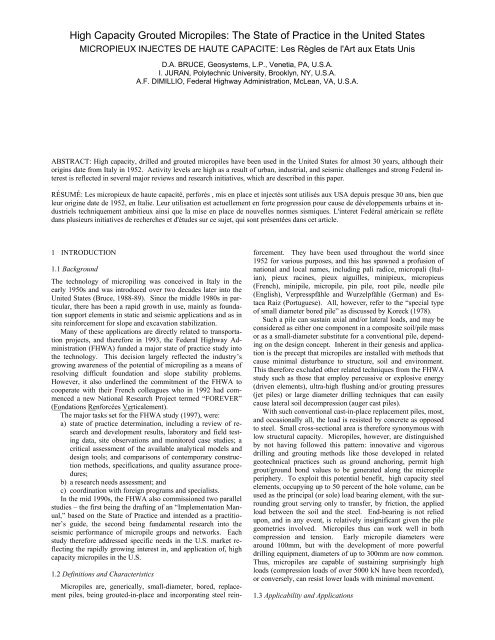
ABSTRACT: <strong>High</strong> capacity, drilled and grouted micropiles have been used in the United States for almost 30 years, although their<br />
origins date from Italy in 1952. Activity levels are high as a result of urban, industrial, and seismic challenges and strong Federal interest<br />
is reflected in several major reviews and research initiatives, which are described in this paper.<br />
RÉSUMÉ: Les micropieux de haute capacité, perforés , mis en place et injectés sont utilisés aux USA depuis presque 30 ans, bien que<br />
leur origine date de 1952, en Italie. Leur utilisation est actuellement en forte progression pour cause de développements urbains et industriels<br />
techniquement ambitieux ainsi que la mise en place de nouvelles normes sismiques. L'interet Fedéral américain se reflète<br />
dans plusieurs initiatives de recherches et d'études sur ce sujet, qui sont présentées dans cet article.<br />
1 INTRODUCTION<br />
1.1 Background<br />
The technology of micropiling was conceived in Italy in the<br />
early 1950s and was introduced over two decades later into the<br />
United States (Bruce, 1988-89). Since the middle 1980s in particular,<br />
there has been a rapid growth in use, mainly as foundation<br />
support elements in static and seismic applications and as in<br />
situ reinforcement for slope and excavation stabilization.<br />
Many of these applications are directly related to transportation<br />
projects, and therefore in 1993, the Federal <strong>High</strong>way Administration<br />
(FHWA) funded a major state of practice study into<br />
the technology. This decision largely reflected the industry’s<br />
growing awareness of the potential of micropiling as a means of<br />
resolving difficult foundation and slope stability problems.<br />
However, it also underlined the commitment of the FHWA to<br />
cooperate with their French colleagues who in 1992 had commenced<br />
a new National Research Project termed “FOREVER”<br />
(Fondations Renforcées Verticalement).<br />
The major tasks set for the FHWA study (1997), were:<br />
a) state of practice determination, including a review of research<br />
and development results, laboratory and field testing<br />
data, site observations and monitored case studies; a<br />
critical assessment of the available analytical models and<br />
design tools; and comparisons of contemporary construction<br />
methods, specifications, and quality assurance procedures;<br />
b) a research needs assessment; and<br />
c) coordination with foreign programs and specialists.<br />
In the mid 1990s, the FHWA also commissioned two parallel<br />
studies – the first being the drafting of an “Implementation Manual,”<br />
based on the State of Practice and intended as a practitioner’s<br />
guide, the second being fundamental research into the<br />
seismic performance of micropile groups and networks. Each<br />
study therefore addressed specific needs in the U.S. market reflecting<br />
the rapidly growing interest in, and application of, high<br />
capacity micropiles in the U.S.<br />
1.2 Definitions and Characteristics<br />
<strong>Micropiles</strong> are, generically, small-diameter, bored, replacement<br />
piles, being grouted-in-place and incorporating steel reinforcement.<br />
They have been used throughout the world since<br />
1952 for various purposes, and this has spawned a profusion of<br />
national and local names, including pali radice, micropali (Italian),<br />
pieux racines, pieux aiguilles, minipieux, micropieus<br />
(French), minipile, micropile, pin pile, root pile, needle pile<br />
(English), Verpresspfähle and Wurzelpfähle (German) and Estaca<br />
Raiz (Portuguese). All, however, refer to the “special type<br />
of small diameter bored pile” as discussed by Koreck (1978).<br />
Such a pile can sustain axial and/or lateral loads, and may be<br />
considered as either one component in a composite soil/pile mass<br />
or as a small-diameter substitute for a conventional pile, depending<br />
on the design concept. Inherent in their genesis and application<br />
is the precept that micropiles are installed with methods that<br />
cause minimal disturbance to structure, soil and environment.<br />
This therefore excluded other related techniques from the FHWA<br />
study such as those that employ percussive or explosive energy<br />
(driven elements), ultra-high flushing and/or grouting pressures<br />
(jet piles) or large diameter drilling techniques that can easily<br />
cause lateral soil decompression (auger cast piles).<br />
With such conventional cast-in-place replacement piles, most,<br />
and occasionally all, the load is resisted by concrete as opposed<br />
to steel. Small cross-sectional area is therefore synonymous with<br />
low structural capacity. <strong>Micropiles</strong>, however, are distinguished<br />
by not having followed this pattern: innovative and vigorous<br />
drilling and grouting methods like those developed in related<br />
geotechnical practices such as ground anchoring, permit high<br />
grout/ground bond values to be generated along the micropile<br />
periphery. To exploit this potential benefit, high capacity steel<br />
elements, occupying up to 50 percent of the hole volume, can be<br />
used as the principal (or sole) load bearing element, with the surrounding<br />
grout serving only to transfer, by friction, the applied<br />
load between the soil and the steel. End-bearing is not relied<br />
upon, and in any event, is relatively insignificant given the pile<br />
geometries involved. <strong>Micropiles</strong> thus can work well in both<br />
compression and tension. Early micropile diameters were<br />
around 100mm, but with the development of more powerful<br />
drilling equipment, diameters of up to 300mm are now common.<br />
Thus, micropiles are capable of sustaining surprisingly high<br />
loads (compression loads of over 5000 kN have been recorded),<br />
or conversely, can resist lower loads with minimal movement.<br />
1.3 Applicability and Applications
<strong>Micropiles</strong> are mainly used in the U.S. for structural support, but<br />
are becoming increasingly popular for in situ reinforcement<br />
(Figure 1). This paper reviews only the former application<br />
wherein groups of Case 1 micropiles (Section 2 below) are employed<br />
to accept load directly, as small diameter substitutes for<br />
other pile types. <strong>Micropiles</strong> are used to solve problems where<br />
logistical and/or geotechnical factors conspire to rule out other<br />
types of support.<br />
Physical constraints include<br />
• Situations with low overhead clearance;<br />
• Tight working conditions inside existing structures;<br />
• Sites with limited plan area access, e.g., in hallways or<br />
against a face of walls; and<br />
• Situations where it is necessary to attach small piling elements<br />
directly through the existing foundation elements.<br />
Geotechnical constraints include<br />
• Karstic limestone geology (with voids or soil-filled solution<br />
cavities);<br />
• Bouldery ground or glacial till;<br />
• Variable and/or random fill;<br />
• Underlying existing foundations or man-made obstructions;<br />
• Rock formations with variable weathering (e.g., hard zones<br />
overlying softer layers); and<br />
• Soils under a high water table.<br />
<strong>Micropiles</strong> offer the following advantages<br />
• Small and powerful equipment is used to negotiate tight<br />
physical spaces;<br />
• Drilling is quiet, vibration free, and causes little or no loss of<br />
ground around each pile installation;<br />
• Drill spoil can be diverted from the hole location to provide a<br />
clean environment within operating facilities;<br />
• The drilling equipment can be used to install tie-down anchors<br />
that provide the primary uplift resistance for vertical<br />
pile load testing;<br />
• Larger casing pipes can be used in the upper portions of the<br />
piles to obtain significant lateral load resistance; and<br />
• Many variations of drilling, grouting, and structural configurations<br />
make for a fully customized and optimal solution.<br />
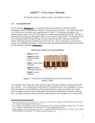
Various practitioners have proposed classifications based on diameter,<br />
some constructional process, or by the type of reinforcement.<br />
The FHWA team derived a new classification which<br />
is now being used nationwide and is based on two criteria:<br />
• The philosophy of system behavior, and<br />
• The method of grouting.<br />
The former criterion dictates the basis of the overall design<br />
concepts, and the latter is the principal determinant of<br />
grout/ground bond capacity.<br />
2.1 Classification Based on Philosophy of Behavior<br />
<strong>Micropiles</strong> are usually designed to transfer structural loads to<br />
more competent or stable strata. They therefore act as substitutes<br />
or alternatives for other conventional pile systems. For<br />
axially loaded piles, the pile/ground interaction is in the form of<br />
side shear and so is restricted to that zone of ground immediately<br />
surrounding the pile. For micropiles used as in situ reinforcements<br />
for slope stabilization, pile/ground interaction occurs only<br />
relatively close to the slide plane, although above this level, the<br />
pile group may also provide a certain degree of continuity to the<br />
pile/ground composite structure. In both cases, however, the pile<br />
(principally the reinforcement) resists directly the applied loads.<br />
This is equally true for cases when individual piles or groups of<br />
piles are used. In this context, a group is defined as a tight collection<br />
of piles, each of which is subjected to direct loading.<br />
Depending on prevailing codes relating to pile group design, individual<br />
pile design capacity may have to be reduced in conformity<br />
with conventional “reduction ratio” concepts. These concepts<br />
were typically developed for driven piles, and so this<br />
restriction is almost never enforced for micropiles, given their<br />
mode of construction which tends to improve, not damage, the<br />
soil mass between piles.<br />
When axially-loaded piles of this type are designed to transfer<br />
their load only within a remote founding stratum, pile head<br />
movements will occur during loading, in proportion to the length<br />
and composition of the pile shaft between structure and the<br />
founding stratum, and the load. Piles of this type can be preloaded<br />
(Bruce et al. 1990) to ensure that the overlying structure<br />
can be supported without further movements occurring. Equally,<br />
if suitably competent ground conditions exist all the way down<br />
from below the structure, then the pile can be fully bonded to the<br />
Review of<br />
Applications<br />
Structural<br />
Support<br />
In-Situ<br />
Reinforcement<br />
Foundation<br />
for New<br />
Structures<br />
Underpinning<br />
of Existing<br />
Foundations<br />
Seismic<br />
Retrofitting<br />
Embankment,<br />
Slope, and<br />
Landslide<br />
Stabilization<br />
Soil<br />
Strengthening<br />
and<br />
Protection<br />
Settlement<br />
Reduction<br />
Structural<br />
Stability<br />
Repair /<br />
Replacement<br />
of Existing<br />
Foundations<br />
Arresting /<br />
Prevention of<br />
Movement<br />
Upgrading of<br />
Foundation<br />
<strong>Capacity</strong><br />
Figure 1. Classification of micropile applications.<br />
2. CLASSIFICATION OF MICROPILES USED IN THE U.S.
soil over its entire length and so movements under equivalent<br />
loads will be smaller than in the previous case. These directly<br />
loaded piles, whether for axial or lateral loading conditions, are<br />
referred to as CASE 1 elements. They comprise virtually all<br />
North American applications to date, and at least 90 percent of<br />
all known international applications.<br />
On the other hand, one may distinguish the small group of<br />
CASE 2 structures. Dr. Fernando Lizzi of Naples introduced the<br />
concept of micropiling when he patented the Αroot pile≅ (palo<br />
radice) in 1952. The name alone evokes the concept of support<br />
and stabilization by an interlocking, three-dimensional network<br />
of reticulated piles similar to the root network of a tree. This<br />
concept involves the creation of laterally confined soil/pile composite<br />
structure that can provide underpinning, stabilization or<br />
earth retention. In this case, the piles are not heavily reinforced<br />
since they are not individually and directly loaded: rather, they<br />
circumscribe a zone of reinforced, composite, confined material<br />
that offers resistance with minimal movement. The piles are<br />
fully bonded over their entire length and so for this case to work,<br />
the soil over its entire profile must have some reasonable degree<br />
of competence. Lizzi=s research (1982) has shown that a positive<br />
“network effect” is achieved in terms of load/movement performance,<br />
such is the effectiveness and efficiency of the reticulated<br />
pile/soil interaction in the composite mass.<br />
It is clear, therefore, that the basis of design for a CASE 2<br />
network is radically different from a CASE 1 pile (or group of<br />
piles). This is addressed in Volume 2 of the FHWA study.<br />
Notwithstanding this difference, however, there will be occasions<br />
where there are applications transitional between these designs<br />
(although this attractive possibility is currently, conservatively,<br />
ignored for pile groups), while a CASE 2 slope stability<br />
structure may have to consider direct pile loading conditions (in<br />
bending or shear) across well defined slip planes. By recognizing<br />
these two basic design philosophies, even those transitional<br />
cases can be designed with appropriate engineering clarity and<br />
precision.<br />
2.2 Classification Based on Method of Grouting<br />
The successive steps in constructing micropiles are drill; place<br />
reinforcement; and place and typically pressurize grout (usually<br />
involving extraction of temporary steel drill casing).<br />
There is no question that the drilling method and technique<br />
will affect the magnitude of the grout/ground bond which can be<br />
mobilized, while the act of placing the reinforcement cannot be<br />
expected to influence this bond development. Generally, however,<br />
international practice both in micropiles and ground anchors<br />
confirms that the method of grouting is generally the most<br />
sensitive construction control over grout/ground bond development.<br />
The following classification of micropile type, based<br />
primarily on the type and pressure of the grouting (Figure 2)<br />
is therefore adopted.<br />
Type A: Grout is placed in the pile under gravity head only.<br />
Since the grout column is not pressurized, sand-cement<br />
Αmortars≅, as well as neat cement grouts, may be used.<br />
Type B: Neat cement grout is injected into the drilled hole as<br />
the temporary steel drill casing or auger is withdrawn. Pressures<br />
are typically in the range of 0.3 to 1 MPa, and are limited by the<br />
ability of the soil to maintain a grout tight Αseal≅ around the casing<br />
during its withdrawal, and the need to avoid hydrofracture<br />
pressures and/or excessive grout consumptions, particularly in<br />
upper, permeable, fills.<br />
Type C: Neat cement grout is placed in the hole as for Type<br />
A. Between 15 and 25 minutes later, and so before hardening of<br />
this primary grout, similar grout is injected, once, via a preplaced<br />
sleeved grout pipe at a pressure of at least 1 MPa. This type of<br />
pile, referred to in France as IGU (Injection Globale et Unitaire),<br />
seems to be common practice only in that country to date.<br />
Figure 2. Classification of micropile based on type of grouting.<br />
Type D: Neat cement grout is placed in the hole as for Type<br />
A. Some hours later, when this primary grout has hardened,<br />
similar grout is injected via a preplaced sleeved grout pipe. In<br />
this case, however, a packer is used inside the sleeved pipe so<br />
that specific horizons can be treated, several times if necessary,<br />
at pressures of 2 to 8 MPa. This is referred to in France as IRS<br />
(Injection Répétitive et Sélective), and is common practice<br />
worldwide, including the U.S.<br />
2.3 Combined Classification<br />
<strong>Micropiles</strong> are therefore allocated classification numbers denoting<br />
the philosophy of behavior (CASE 1 or CASE 2), which relates<br />
fundamentally to the design approach, and a letter denoting<br />
the method of grouting (Type A, B, C, or D), which reflects the<br />
major constructional control over capacity.<br />
In the U.S. the most common pile types are 1A (for rock and<br />
very stiff cohesives), 1B (non-cohesives), and 1D (cohesives).<br />
3. ASPECTS OF DESIGN, CONSTRUCTION, AND TESTING<br />
3.1 Design<br />
An extremely thorough review was provided by Juran et al.<br />
(1999), and detailed guidance is given in the FHWA Implementation<br />
Manual (1997). To date, however, design procedures have<br />
not been unified or codified nationally, and typically designers<br />
have had to observe the rules of the numerous local or city building<br />
codes, often focussed on other more “conventional” types of<br />
pile. This has not helped the expansion of the technique in certain<br />
geographic locations. In general, however, the following<br />
statements reflect common practice.<br />
• Steel casing for load bearing must ASTM A252 Grade 3, to a<br />
minimum yield stress of 550 MPa.<br />
• Core steel reinforcing is normally Grade 60, 75, or 80 (ASTM<br />
A615, 616, and 617, respectively) or less commonly Grade<br />
150 (ASTM 722).<br />
• Grouts are typically neat, low water cement ratio mixes with<br />
a minimum 28-day unconfined compressive strength of<br />
30 MPa.<br />
• The micropile working load is calculated from using 40 to<br />
45% of the steel yield value plus 30 to 40% of the grout unconfined<br />
compressive strength, ignoring strain incompatibility<br />
issues.<br />
• For geotechnical design, end bearing is typically ignored, and<br />
empirical data used to determine the appropriate grout-soil
ond. For the typical range of micropile diameters and installation<br />
methods, this ultimate figure can range from, say<br />
50 kN/m (soft clay) to 500 kN/m (dense gravels).<br />
• For the infrequent occasions when micropiles are designed as<br />
simple struts between the structure and a particularly resistant<br />
bedrock surface of sufficient “punching” resistance, the internal<br />
pile design clearly governs.<br />
3.2 Construction<br />
Most micropiles are installed in urban or industrial settings<br />
where the upper strata at least may be very challenging to drill.<br />
Contractors have therefore evolved many overburden and rock<br />
drilling methods (Bruce, 1989) to guarantee penetration without<br />
causing damage to the structure or the environment. Most feature<br />
water flush and some form of rotary duplex drilling. Contractors<br />
have been quick to take advantage of the valuable developments<br />
in high powered, mobile hydraulic drill rigs, mainly as<br />
produced by European sources. Reinforcement is provided in<br />
lengths commensurate with the overhead access, which may be<br />
as little as 2.5 m. Casings are threaded and reinforcing bars are<br />
coupled. No welded connections are permitted. Grouting techniques<br />
are similar to those of ground anchoring practice, and at<br />
their best, feature colloidal mixers and strong quality control<br />
over mix designs and injection parameters.<br />
3.3 Load Testing<br />
It is common on projects of significant scale and scope to conduct<br />
a test pile program prior to production work commencing.<br />
The number of piles reflects the variability of the ground and the<br />
extent of prior experience in such conditions. Typically between<br />
two and six such piles are installed and usually they are tested to<br />
failure to provide ultimate values. Thereafter, it is common to<br />
subject a certain small percentage of production piles to some<br />
quicker and more economical test to verify adequacy of routine<br />
installation methods. Testing is typically conducted to the relevant<br />
ASTM standards for compressive, tensile, and lateral loading,<br />
often modified to incorporate specific features from other<br />
sources, e.g., PTI Recommendations for Rock and Soil Anchors<br />
(1996). Micropile testing can be relatively inexpensive and the<br />
increasing volume of published data has undoubtedly encouraged<br />
the expansion of the technology nationwide.<br />
4. RESEARCH AND DEVELOPMENT<br />
As has been common for virtually every new geotechnical process<br />
introduced into the U.S. in the last 25 years, the onus (and<br />
cost) of research and development has largely fallen on the specialty<br />
contractors themselves. During the beginning of the rapid<br />
growth of usage in the mid to late 1980s much invaluable and<br />
fundamental research was conducted, either as “extra effort” on<br />
existing sites (Bruce, 1992), or as specially funded programs in<br />
cooperation with universities (e.g., Bruce et al., 1993). However,<br />
responding to the aftermath of the Loma Prieta Earthquake<br />
in California, the California Department of Transportation, the<br />
FHWA, and industry, partnered to conduct a very large and important<br />
full-scale field test in South San Francisco in 1992 (DFI,<br />
1993). This provided a great deal of useful information.<br />
As further offshoots of the 1993 FHWA-FOREVER initiative,<br />
fundamental seismic research was conducted by Juran and<br />
coworkers (2000) at the Polytechnic University of Brooklyn,<br />
while other researches into micropile networks have been conducted<br />
by Cornell University (Mason, 1999), and the U.S. Marine<br />
Corps (Weinstein, 2000). From 1997 onwards, the International<br />
Workshop on <strong>Micropiles</strong> (IWM) has convened to hold<br />
three major workshops (Seattle, Ube, and Türkü) involving leading<br />
practitioners and theoreticians from North America, Europe,<br />
and Japan. Most recently there are strong indications that leading<br />
trade associations like the International Association of Foundation<br />
Drilling (ADSC) (formerly referred to as the Association<br />
of Drilled Shaft Contractors) are becoming keen to cosponsor research,<br />
while a committee of the Deep Foundations Institute is<br />
devoted to micropiles, and to issuing guideline specifications.<br />
This level of activity is perhaps the clearest evidence of a vibrant<br />
and growing micropile market in the U.S.<br />
5. REFERENCES<br />
American Society for Testing and Materials. (1998a). “A252-98:<br />
Standard specification for welded steel pipe piles.”<br />
American Society for Testing and Materials. (1998b).<br />
“A722/A722M-98: Standard specification for uncoated highstrength<br />
steel bar for prestressing concrete.”<br />
American Society for Testing and Materials. (2000a).<br />
“A615/A615M-00: Standard specification for deformed and<br />
plain billet – steel bars for concrete reinforcement.”<br />
American Society for Testing and Materials. (2000b).<br />
“A996/A996M-00: Standard specification for rail-steel and<br />
axle-steel deformed bars for concrete reinforcement.” (replaced<br />
A616/A616M and A617/A617M).<br />
Bruce, D.A. (1988 – 1989). “Aspects of minipiling practice in<br />
the United States.” Ground Engineering, Vol. 21, No. 8<br />
pp. 20-33 and Vol. 22, No. 1, pp. 35-39.<br />
Bruce, D.A. (1989). “Methods of Overburden Drilling in Geotechnical<br />
Construction-- A Generic Classification.” Ground<br />
Engineering 22 (7), pp. 25-32. Also published in “Drill Bits -<br />
The Official Publication of the International Drilling Federation”,<br />
Fall 1989, pp. 7, 8, 110, 11, 13, 14.<br />
Bruce, D.A. (1992). “Recent Progress in American Pinpile<br />
Technology.” Proc. ASCE Conference, “Grouting, Soil Improvement<br />
and Geosynthetics, New Orleans, LA, Feb. 25-28,<br />
pp. 765-777.<br />
Bruce, D.A., S.L., Pearlman, and J.H. Clark. (1990).<br />
ΑFoundation Rehabilitatin of the Pocomoke River Bridge,<br />
MD, Using <strong>High</strong> <strong>Capacity</strong> Preloaded PinPiles.≅ Proc. 7 th Annual<br />
International Bridge Conference, Pittsburgh, PA June<br />
18-20, Paper IBC-90-42, 9 pp.<br />
Bruce, D.A., Bjorhovde, R. and Kenny, J.R. (1993). “Fundamental<br />
Tests on the Performance of <strong>High</strong> <strong>Capacity</strong> PinPiles sm .”<br />
Proc. 18th Annual DFI Conference, Pittsburgh, PA, October<br />
18-20, 33 pp.<br />
Deep Foundations Institute. (1993). “CalTrans Pile Load Test<br />
Results Seminar Proceedings.” Deep Foundations Institute,<br />
Englewood Cliffs, NJ.<br />
Federal <strong>High</strong>way Administration. (1997). “Drilled and <strong>Grouted</strong><br />
<strong>Micropiles</strong>: State of Practice Review, Volumes I, II, III, and<br />
IV.” Prepared for the Federal <strong>High</strong>way Administration, Co-<br />
Principal Investigators D.A. Bruce, I. Juran. Publication<br />
Nos. FHWA-RD-96-016. –017, -018, and –019, July.<br />
Federal <strong>High</strong>way Administration. (1997). “Micropile Design and<br />
Construction Guidelines: Implementation Manual.” Publication<br />
No. FHWA-SA-97-070. June, 317 pp.<br />
Juran, I., D.A. Bruce, A. DiMillio, and A. Benslimane. (1999).<br />
“<strong>Micropiles</strong>: the state of practice. Part II: design of single<br />
micropiles and groups and networks of micropiles.” Ground<br />
Improvement. Vol. 3, No. 3. July.<br />
Juran, I. (2000). Personal communication.<br />
Koreck, H.W. (1978). ΑSmall-Diameter Bored Injection Piles.≅<br />
Ground Engineering, Vol. 11, No. 4 pp. 14-29.<br />
Lizzi, F (1982). Static Restoration of Monuments. Sagep Publisher.<br />
Genoa, Italy.<br />
Mason, J.A. (1999). Personal communication.<br />
Post Tensioning Institute. (1996). “Recommendations for<br />
Prestressed Rock and Soil Anchors,” Phoenix, AZ, 52 p.<br />
Weinstein, G. (2000). Personal communication.