

Download PDF - Gear Technology magazine
Download PDF - Gear Technology magazine
Download PDF - Gear Technology magazine

You also want an ePaper? Increase the reach of your titles
YUMPU automatically turns print PDFs into web optimized ePapers that Google loves.
the geometry factor is directly determined 50 that it may be<br />
used in the current AGMA 218.01 rating standard. Since the<br />
AGMA method currently in. use is a two-dimensional analysis<br />
method. the authors decided to use a two-dimensional boundary<br />
element Note, however, that in many complex root stress<br />
problems, three-dimensional analyses should be used in order<br />
to obtain accurate stress results. Gakwaya et a1(27) show<br />
comparisons of the computational time required by the<br />
boundary element method and the finite element method ..<br />
Hohe(Z9) discusses advantages and disadvantages of the<br />
boundary integral equation method and compares it with the<br />
finite element method for a plane-stress gear-tooth problem ..<br />
Boundary Element and Finite Element Methods<br />
The finiteelement method divides the body that is being<br />
studied into many pieces or elements whose behavior is easier<br />
to approximate than that of the whole body. The equations<br />
describing each element are "assembled" ina. system of linear<br />
equations and are then solved.<br />
The boundary element method,. on the other hand, does<br />
not divide the body under consideration into elements. For<br />
a homogenous. isotropic body with no body forces, the only<br />
causes for displacements and stresses within the body are<br />
loads and displacements applied along the boundary. The<br />
body can be considered to be part of an infinitely extending<br />
material which is subjected to loads along the original boundary.<br />
Thus, if a function which describes the response of an<br />
infinitely extending medium to a point load is known, then<br />
this function can be used to compute Ute response of the body<br />
by moving the point load along the boundary and integrating<br />
each individual response. Therefore, the integration which<br />
is carried out numerically by breaking the boundary into<br />
elements only needs to be carried out along the boundary.<br />
The boundary element method has the advantage of not requiring<br />
that the Interior of the body be divided into twodimensional<br />
elements with only the boundary being divided<br />
into one-dimensional 'elements. Because of its mathematical<br />
complexity and because other references, such as Brebbia, (25)<br />
provide the mathematical details of the boundary element<br />
method. its theoretical basis is not presented in. this article,<br />
However, a summary of its theory is presented in the<br />
Appendix ..<br />
An important advantage of the boundary element method<br />
is that it is usually able to represent areas of stressconcentration<br />
and singularities better than general purpose finite element<br />
methods ..Because only the boundary needs to be made<br />
discrete in boundary element methods. it is possible to. work<br />
with smaller systems of equations and arrive at very accurate<br />
results.<br />
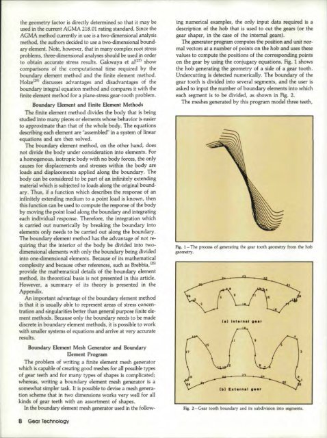
ing numericalexamples, the only input data required is a<br />
description of the hob that is used to cut the gears (or the<br />
gear shaper, in the case of the internal gears) ..<br />
The generator program computes the position and unit normal<br />
vectors at a number of points on the hob and uses these<br />
values to compute the positions of the corresponding points<br />
on the gear by using the conjugacy equations. Fig. 1 shows<br />
the hob generating the geometry of a side of a gear tooth.<br />
Undercutting is detected numerically, The boundary of the<br />
gear tooth is divided into several segm.ents, and the user is<br />
asked to input the number of boundary elements into which<br />
each segment is to be divided, as shown in Fig.. 2.<br />
The meshes generated by this program mode] three teeth,<br />
Fig. 1-The process of generating the gear tooth geometry from the hob<br />
geometry.<br />
Boundary Element Mesh Generator and Boundary<br />
Element Program<br />
The problem of writing a finite element mesh gene.rator<br />
which is capable of creating good meshes for all possible types<br />
of gear teeth and for many types of shapes is complicated;<br />
whereas, writing a boundary element mesh generator is a<br />
somewhat simpler task. It is possible to devise a mesh generation<br />
scheme that in two dimensions works very well for all<br />
kinds of gear teeth with all assortment of shapes.<br />
In the boundary element mesh generator used in the follow-<br />
8 <strong>Gear</strong> <strong>Technology</strong><br />
Fig. 2-<strong>Gear</strong><br />
tooth boundary and its subdivision into segments.


