

Download PDF - Gear Technology magazine
Download PDF - Gear Technology magazine
Download PDF - Gear Technology magazine

Create successful ePaper yourself
Turn your PDF publications into a flip-book with our unique Google optimized e-Paper software.
to describe nonstandard gears. With this parameter, a series<br />
of simple equations can be developed, which s.implify<br />
nonstandard gear geometry calculations and reduce iteration.<br />
The"]" factor is<br />
• Dimensionless<br />
• Easily calculated<br />
• Independent of helix angle<br />
• Independent of the cutter geometry<br />
• Independent of the mating gear<br />
• Unique for the geometry of the gear described.<br />
Nomenclature<br />
and Definitions<br />
Defil1itiotl$. Symbols are defined where they are first used<br />
in this article. For convenience, a list of symbols is provided<br />
in Table L<br />
The subscript ''1'' refers to the pinion, and the subscript<br />
"2" refers to the gear.<br />
Fundamental! PilIamet·ers of the Involute Tooth Form<br />
The involute portions of a. meshing gear pair can be Completely<br />
described in terms of a short list of fundamental<br />
parameters.<br />
Numbers of Teeth. The number of teeth on each gear must<br />
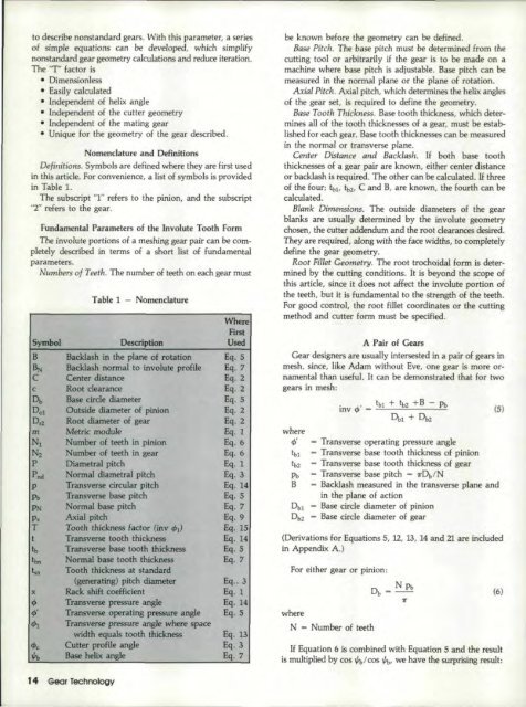
Table 1 - Nomenclature<br />
Where<br />
First<br />
Symbol Description Used<br />
B Backlash in the plane of rotation Eq. 5<br />
~ Backlash normal to involute profile Eq.7<br />
C Center distance Eq.2<br />
c Root clearance Eq. 2<br />
o, Base circle diameter Eq. 5<br />
Dol Outside diameter of pinion Eq. 2<br />
Dr2 Root diameter of gear Eq.2<br />
m Metric module Eq.l<br />
N1 Number of teeth in pinion Eq.6<br />
Nz Number of teeth in gear Eq.6<br />
P Diametral pitch Eq.1<br />
P nd Normal diametral pitch Eq.3<br />
p Transverse circular pitch Eq. 14<br />
Ph Transverse base pitch Eq.5<br />
PN Normal base pitch Eq.7<br />
p" Axial pitch Eq. 9<br />
I<br />
T Tooth thickness Factor (inv 91) Eq. IS'<br />
II t Transverse tooth thickness Eq. 14<br />
I tb Transverse base tooth thickness Eq. 5<br />
i tbn Normal base tooth thickness Eq.7<br />
tsn Tooth thickness at standard<br />
(generating) pitch diameter Eq .. 3<br />
x Rack shift coefficient Eq.1<br />
,p Transverse pressure angle Eq. 14<br />
,p' Transverse operating pressure angle Eq.5<br />
¢I Transverse pressure angle where space<br />
width equals tooth thickness Eq.13<br />
,pc Cutter profile angle Eq.3<br />
th Base helix angle Eq.7<br />
be known before the geometry can be defined.<br />
Base Pitch. The base pitch must be determined from the<br />
cutting tool. or arbitrarily if the gear is to be made on a<br />
machine where base pitch is adjustable .. Base pitch can be<br />
measured in the normal plane or the plane of rotation.<br />
A;dal Pitch. Axial. pitch, which determines the helix angles<br />
of the gear set, is required to define the geometry.<br />
Base Tooth Thickness. Base tooth thickness, which determines<br />
all of the tooth thicknesses of a gear, must be established<br />
for each gear. Base tooth thicknesses can be measured<br />
in the normal or transverse' plane.<br />
Center Distance and Backlash.. If both base tooth<br />
thicknesses of a gear pair are known, either center distance<br />
or backlash is required. The other can be calculated ..[f three<br />
of the four; tbI, tb2, C and B, are known, the fourth can be<br />
calculated.<br />
Blank Dimensions. The outside diameters of the gear<br />
blanks are usually determined by the involute geometry<br />
chosen, thecutter addendum and the root clearances desired.<br />
They are required, along with the face widths, to completely<br />
define the gear geometry.<br />
Root Fillet Geometry. The root trochoidal form is determined<br />
by the cutting conditions. It is beyond the scope of<br />
this article, since it does not affect the involute portion of<br />
the teeth, but it isfundamental to the strength ·of the teeth,<br />
For good control. the root fillet coordinates or the cutting<br />
method and cutter fonn must be specified.<br />
A Pair of <strong>Gear</strong>s<br />
<strong>Gear</strong> designers are usually intersested in a pair of gears in<br />
mesh, since, like Adam without Eve, one gear is more ornamental<br />
than usefuL It can be demonstrated that for two<br />
gears in mesh:<br />
where<br />
1jJ'<br />
fbI<br />
thZ<br />
Ph<br />
B<br />
DbI<br />
Db2<br />
iov ,p' _ tbl + tb2 +B - Pb<br />
Dt.l + Dt.2<br />
- Transverse operating pressure angle<br />
- Transverse base tooth thickness of pinion<br />
- Transverse base tooth thickness of gear<br />
- Transverse base pitch - :1I'Db/N<br />
- Backlash measured in the transverse plane and<br />
in the plane of action<br />
- Base circle diameter of pinion<br />
- Base circle diameter of gear<br />
(Derivations for Equations 5, 12, 13, 14 and 21 are included<br />
in Appendix A.)<br />
For either<br />
where<br />
gear or pinion:<br />
N - Number of teeth<br />
If Equation 6 is combined with Equation 5 and the result<br />
is multiplied by cos %/cos %, we have the surprising result:<br />
(5)<br />
(6)<br />
14 Geor <strong>Technology</strong>


