

Download PDF - Gear Technology magazine
Download PDF - Gear Technology magazine
Download PDF - Gear Technology magazine

You also want an ePaper? Increase the reach of your titles
YUMPU automatically turns print PDFs into web optimized ePapers that Google loves.
Noise To Measured <strong>Gear</strong><br />
vibration people who know little about<br />
gear geometry. Their data may show lots<br />
of peak vibrations that bear no relationship<br />
to what the human ear is hearing<br />
relative to gear quality. Many times the<br />
excitation may even be coming from<br />
another source. such as a rolling element<br />
in a bearing.<br />
Frequency is the key to understanding<br />
gear noise. The problem is how to convert<br />
aural images to visual ones; in other<br />
words. how to find a way to display on<br />
a CRT or on paper what the human ear<br />
is hearing.<br />
<strong>Gear</strong>s As Exciters of Structures<br />
Most of what we hear as "gear noise"<br />
does not come directly from the gear pair<br />
at all. The minute vibrations created by<br />
the gears as they move through mesh are<br />
amplified by resonances in the structural<br />
elements of the housing. such as panels.<br />
ribs, beams, etc. <strong>Gear</strong> noise in a vehicle<br />
generally occurs at tooth mesh frequency<br />
or harmonics of it and occasionaUy at<br />
sidebands of mesh frequency. The gears<br />
are the exciter. The structure resonates,<br />
amplifies the force and converts it to<br />
airborne noise. Transmission error or<br />
non-uniform motion of the gears is the<br />
mechanism of excitation. Transmission<br />
error(3) is the result of small variations<br />
from the correct or ideal tooth geometry,<br />
as well as runout. and can be measured<br />
in the production process by the use of<br />
single flank composite testing techniques.<br />
In the case of vehicle noise, these variations<br />
can be as small as 25 to 150 microinches.<br />
depending on the frequency.<br />
Transmission<br />
Error Testing<br />
Transmission error testing is done by<br />
rolling gears together with backlash and<br />
at their proper operating center distance.<br />
The input and output angular motion<br />
characteristics are measured by an encoder<br />
system and electronics as shown<br />
in Fig. la. The data can be presented<br />
in graphic analog form, as shown in<br />
Fig. lb. or can be further processed by<br />
Fast Fourier Transform (FFT) techniques<br />
to aid in pinpointing the source of excitation.<br />
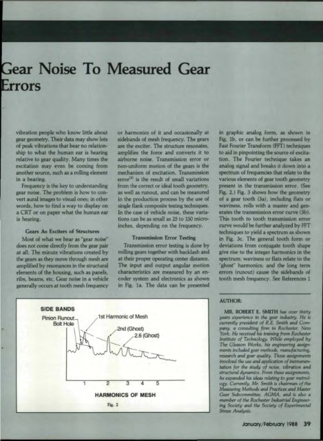
The Fourier technique takes an<br />
analog signal and breaks it down into a<br />
spectrum of frequencies that relate to the<br />
various elements of gear tooth geometry<br />
present in the transmission error. (See<br />
Fig. 2.) Fig. 3 shows how the geometry<br />
of a gear tooth (3a), including flats or<br />
waviness. rolls with a master and generates<br />
the transmission error curve (3b).<br />
This tooth to tooth transmission error<br />
curve would be further analyzed by FFT<br />
techniques to yield a spectrum as shown<br />
in Fig. 3c. The general tooth form or<br />
deviations from conjugate tooth shape<br />
give rise to the integer harmonics in the<br />
spectrum; waviness or flats relate to the<br />
"ghost" harmonics; and the long tenn<br />
errors (runout) cause the sidebands of<br />
tooth mesh frequency. See References 1<br />
S'ID,E BANDS<br />
Pinion Runout<br />
Bolt Hole<br />
I<br />
1st Harmonic<br />
,of MesI1<br />
//200 (Ghost. - )<br />
--........ 2.6 (Ghost)<br />
11 2 4 5<br />
HARMONICS<br />
Fig. 2<br />
OF MESH<br />
AlJIHOR:<br />
MR. ROBERT E. SMITH luis 0'f1flr thirty<br />
years experience i" the glflF' industry. He is<br />
currently presidmt of R.E. Smith and Company.<br />
a consulting firm in RoclwstB'. New<br />
York. He received his fnlining from Roclwstn-<br />
Institute of <strong>Technology</strong>. Whik employed by<br />
The Gleason Works. his enginRmng auignments<br />
included glflF' methods. rtVllIufrrcturing.<br />
research and gear quality. TIwse QSSignments<br />
involved the use and appliaztion of inst'runvntatio"<br />
for the study of noiM, uibnItio" and<br />
structural dyrumtics. From t~ taignments,<br />
he expanded his Ukas relming to gNr mmology.<br />
Currently, Mr. Smith is chaimum of the<br />
Measuring Methods and Practices and Master<br />
<strong>Gear</strong> SubcommiHee, AGMA. and is also a<br />
member of the Rochester lruIustrWI Engm«ring<br />
Society and th, Society of Experimental<br />
StrEss Analysis.<br />
January!February 1988 39


