

Download PDF - Gear Technology magazine
Download PDF - Gear Technology magazine
Download PDF - Gear Technology magazine

You also want an ePaper? Increase the reach of your titles
YUMPU automatically turns print PDFs into web optimized ePapers that Google loves.
Mesh<br />
1<br />
2<br />
3<br />
4<br />
5<br />
6<br />
7<br />
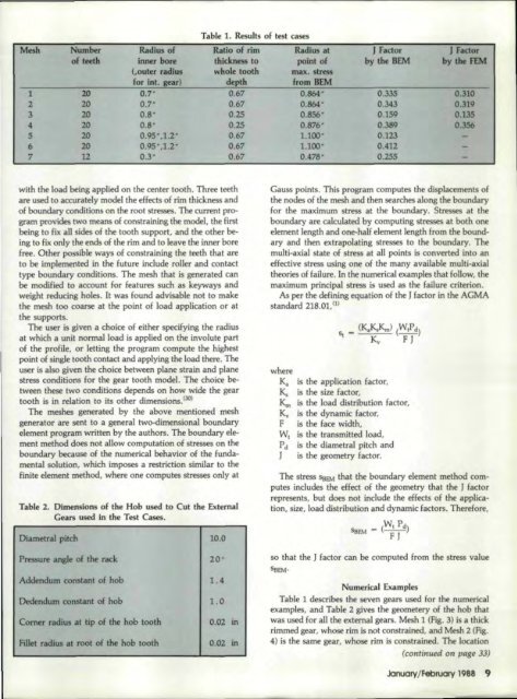
TaMe' 1. Results<br />
oE~est cases<br />
Number Radius of Ratio of rim Radius at J Factor J Factor<br />
of teeth inner bore thickness to point of by the HEM by the FEM<br />
Couter radius whole tooth max. stress<br />
for into gear) depth from HEM<br />
20 0.7" 0.67 0.864" 0.335 0.310<br />
2D 0.7" 0.67 0.864 • 0.343 0.319<br />
20 O.S' 0.25 0.856" 0.159 0.135<br />
20 O.S- 0.25 0.876" 0.389 0.356<br />
20 0.9S",1.2" 0.67 1.100' 0.123<br />
20 0.95",1.2 • 0.67 1.100" 0.412<br />
12 0.3- 0.67 0.478- 0.255<br />
with the load being applied on the center tooth. Three teeth<br />
are used to aocurately model the ,effects of rim ,thickness and<br />
of boundary conditions on the root stresses. The current program<br />
provides two means of ,oonstraining the model, the first<br />
being to .fixall sides of the tooth support, and the other being<br />
'to,fix. only 'the ends of the rim and to leave the inner bore<br />
free ..Other possible ways of constraining the teeth that are<br />
to be implemented in the future include roller and contact<br />
type boundary cenditions. The mesh that is generated can<br />
be modilied toaccount for features such as keyways and<br />
weight fil~ducing holes. It was found advisable not to make<br />
the mesh too coarse at the point of load application or at<br />
the supports ..<br />
The user is given at. choioe IOf either specifying the radius<br />
at which a unit normal load is applied on the involute part<br />
of the profile, or letting the program compute 'the highest<br />
point of single tooth contact and applying the load there. The<br />
user is also given the choice between plane strain and plane<br />
stress conditions for the gear tooth model. The ehelce between<br />
these two condltions depends on how wide the gear<br />
tooth is i.n relation to its other dimensions.(30)<br />
The meshes generated by the above mentioned mesh<br />
generator are sent 'loa general two-dimensional boundary<br />
element program wriUen by the authors. The boundary element<br />
method does not all.ow eomputation of stresses on. the<br />
boundary because' of the numerical behavior of the fundamental<br />
solution, which imposesa. restriction similar to the<br />
finite element method, where one computes stresses only at<br />
Table 2. D.imensions of the Hob used Ito Cut the External<br />
<strong>Gear</strong>s used in. ,the Test Cases.<br />
Diametral pitch 10.0<br />
Gauss points. This program computes the displacements of<br />
the nodes of the mesh and then searches along the boundary<br />
for Ithe maximum stress at the boundary. Stresses at the<br />
boundary are calculated by computing stresses at both one<br />
element length and one-half element length from the boundary<br />
and then ,extrapolating stresses Ito the boundary. The<br />
multt-axial state of stress at all points is converted into, an<br />
effective stress usmg one of the many available multi-axlal<br />
theories of failure. In the numerical examples that follow, the<br />
maximum principal stress is used as the failure ,criterion.<br />
As per Ithe defining equation IOf the] fact.1011' in the AGMA<br />
standard .218.01, U) -<br />
where<br />
Kl!, is 'the appUcation factor.<br />
~ is the size factor.<br />
Km is the load distribution factor,<br />
K" is the dynamic factor,<br />
.F is the fa.ce width,<br />
WI is the 'transmitted load,<br />
Pd is the diametral pitch and<br />
] is the geometry Eactor.<br />
The stress 'SeEM that the boundary element method computes<br />
tndudes, the effect of the geometry that the J factor<br />
represents. but does not include the effects 'of the application,<br />
size, load distribution and dynamic factors. Ther,efoJle,<br />
WI P d<br />
SBEM - (-)<br />
F J<br />
Pressure angle of the rack<br />
Addendum constant of hob<br />
Dedendum constant of hob<br />
Comer radius at tip of the hob tooth<br />
Fillet radius at root of the hob tooth<br />
20"<br />
1.4<br />
1.0<br />
0.02 in<br />
0.02 in<br />
so that the' factor can be computed from the stress value<br />
SBEM·<br />
Numerical<br />
Examples<br />
Table 1describes the seven gears used for the numerical<br />
example r and Table 2 gjves the geometery of the hob that<br />
was used for all the external gears. Mesh 1 (Fig. 3) isa ,thick<br />
rimmed gear, whose rim, is not constrained, and Mesh 2. (fig.<br />
41) is 'the same gear, whose rim is constrained. The location<br />
(cotdinued on page 33)<br />
January/February 19,88 9'


