

Download PDF - Gear Technology magazine
Download PDF - Gear Technology magazine
Download PDF - Gear Technology magazine

Create successful ePaper yourself
Turn your PDF publications into a flip-book with our unique Google optimized e-Paper software.
the transverse pressure angle where the tooth thickness equals<br />
the space width.<br />
Before describing the proposal, the rack shift method of<br />
describing nonstandard involute gears and some of its limitations<br />
are discussed.<br />
Rack Shift Coefficient - Two Definitions<br />
Outside Diameter Method. One definition of rack shift<br />
coefficient is given by Maag:(l)<br />
'The amount of the radial displacement of the datum line<br />
from the position touching the reference circle is termed addendum'<br />
moddicazion, This amount is given a positive sign<br />
in the calculations when the displacement is away from the<br />
center of the gear, anda negadve sign when towards the'<br />
center of the gear .. , .The addendum modification coefficient<br />
~ is the amount of addendum modification measured in terms<br />
of the diemetral pitch or module,<br />
Addendum Modification = x (or x.m) (1)<br />
p<br />
The dimensions of the gears can be determinedas the so-called<br />
zero backlash gearing by means of a system of equations.<br />
(In practice the backlash is obtained by the tolerances on the<br />
theoretical, nominal dimension.)"<br />
This definition, which will be called the outside diameter<br />
(OO) method, is useful because, if root clearances are kept<br />
standard, the center distance can easily be calculated without<br />
confusing the calculation with considerations of operating<br />
backlash. (See Figs. 1 & 2.) It is dear that, even without using<br />
a dimensionless coefficient .<br />
where<br />
C = 001 + Dr2 + c (2)<br />
2<br />
Dol = Outside diameter of pinion<br />
Dr2 = Root diameter of gear<br />
C = Center distance<br />
e =, Root clearance.<br />
The geometry is calculated as Hthe gear were cut by feeding<br />
ill hob in from the outside diameter to standard depth, then<br />
side cutting to achieve the desired backlash.<br />
The' gear data block includes "backlashaUowancein this<br />
gear", which specifies thearnount of this side cutting . For<br />
gears which are to run on widely spread centers, this backlash<br />
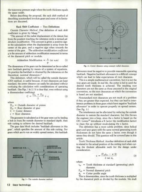
'-----<br />
C --..-.I<br />
Fig. 2 - Center distance using constant radial clearance.<br />
allowance must be negative to provide reasonable operating<br />
backlash. Negative backlash allowance is a difficult concept<br />
which can lead to false expectations of root clearance, -<br />
This is a simple mathematical convention, but it is not the<br />
way gearsare made. In real life, the cutter is fed in until the<br />
desired tooth thickness isa.chieved. The resulting root<br />
diameters are not the same as those assumed in the original<br />
convention, so the root clearances on which the convention<br />
is based<br />
are not standard.<br />
Nonstandard root clearances are not much ofa problem<br />
if they are greater than expected, but they can lead to interterence<br />
problems in those gears which have negative "backlash<br />
allowance" in order to operate properly on spread centers ...<br />
(See fig. 3.)<br />
The interference can be alleviated by reducing the outside<br />
diameter to restore the standard clearance, but this throws<br />
the engineer into ill loop, since the x factor is based on the<br />
00. Lorenz(2.)introduces a K factor (tip modification factor)<br />
to dean this up without recalculating the x factor.<br />
This definition has a more subtle problem, since helical<br />
gears and spur gears with the same normal generating tooth<br />
thicknesses do not have the same x factor, even though it<br />
seems they should. This question will be covered later in this<br />
article.<br />
Tooth Thlcknes« Method. Another definition of rack shift<br />
is related to Ute actual position of the cutting tool when cutting<br />
the thickest allowable teeth for the design under<br />
consideration ..<br />
Wndtsn - '1'12)<br />
x = (3"<br />
Fig. ~- The outside diameter method.<br />
where<br />
tsn = Tooth thickness at standard (generating) pitch<br />
diameter.<br />
P nd = Normal diametral pitch<br />
;:Pc = Cutter profile angle<br />
This is dimensionless, since the tooth thickness is multiplied<br />
by the diametral pitch or divided by the module. We shall<br />
12 Sear Techno'iogy


