

Download PDF - Gear Technology magazine
Download PDF - Gear Technology magazine
Download PDF - Gear Technology magazine

Create successful ePaper yourself
Turn your PDF publications into a flip-book with our unique Google optimized e-Paper software.
facilitate the necessary mesh calculations, even if the two parts<br />
are made with widely diHerentcutting tools, as is the case<br />
here. The complete geometry of this gear set is shown as<br />
Example 6 in Appendix B.<br />
Mesh With A Hob. The T factor as derived is valid for<br />
meshes where the axes of rotation of the two members are<br />
parallel, but not valid in hobbing or shaping with a rack<br />
shaped cutter set in. the normal plane. In these cases, it is<br />
simple to convert the tool. geometry to its equivalent rack<br />
in the transverse plane by calculating its transverse pressure<br />
angle using Equation 17,. For example, the 35 tooth helical<br />
gear of Example 2 might be cut with a standard hob with<br />
a 20 Q norma] profile angle. The transverse pressure angle of<br />
the hob, ¢T = 21.6971 0 and T = .019204. Example 7 in<br />
Appendix B shows the complete geometry of this gear set,<br />
Establishing Root and Outside D.iameters.. The examples<br />
given here establish the foot diameters of the gear and pinion<br />
from the cuttirlg conditions, using the generating diameter<br />
and tooth thickness to establish the cutting position of the<br />
cutter, and calculating the tip position of the cutter from the<br />
actual. cutter geometry. This allows the use of different tools<br />
for the gear and pinion if desired. The shaper cuHer and hob<br />
examples show how this works. The outside diameters are<br />
chosen to give standard root clearances from the root<br />
diameters of the mating parts, except in the cutting tool examples,<br />
where the root clearance with the cutter is zero.<br />
The resulting whole depths vary from standard in order<br />
to maintain the designed clearances. This system is not required,<br />
but it has the advantage of automatical.ly maintaining<br />
equal cutting depths for gear and pinion.<br />
Limit Diameter for Minimum Tip Land. Pinions designed<br />
to operateon widely spread centers run the risk of having<br />
tip lands which are too small for good operation or for proper<br />
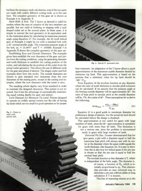
Fig. 5 - Pinion<br />
meshwith<br />
special rack.<br />
in<br />
F.ig.. 6-SpecialB D generated .r.1ck.<br />
heat treatment. An .adaptation of the T ta.etor allows a quick<br />
approximation of the maximum usable diameter limited by<br />
minimum tip land. This approximation is based on the<br />
premise that a minimum value for tip land should be<br />
.300"/P nd •<br />
From Equation 14 the involute function at .any diameter<br />
where the ratio of tooth thickness to circular pitch is known.<br />
can be cal.culaled. If we assume ,that the pressure angle at<br />
the limiting outside diameter will be appro.xima'lely 40°, 'the<br />
ratio of base pitch to cwcular pitch at the outside diameter<br />
will be .776,theoosineof 40 0 • These assumptions let lIS derive<br />
the following:<br />
.!'(tbn<br />
- ·08PN)<br />
mvtbJDmal< - --'-..:::::.:...-....:..:.:;..<br />
NPN<br />
(21)<br />
Equation 21 is a good guide to maximum diameter fer<br />
preliminary design of pinions, but the actual tip land should<br />
be calculated beIor1! the design is finalized ..<br />
This approximation is not IlRfuli for gears with large<br />
numbers of teeth, since the 40" approximation is unrealistic<br />
for gears with more than. 40 teeth. This limitation is<br />
nota serious one, since the problem is encountered<br />
f3IeIy in gears with Large n~mbe_rs of IfeeLh.<br />
Universal Pin Size. Grosser demonstrated that f.or<br />
SPUl' gears, a pin with a dia_meter equal to half the<br />
transverse base pitch will always rest with its center<br />
at the diameter where the space width equals the<br />
tooth thickness. (See Equation 13). It is ,easy to show<br />
that this is also, true fo.r helical gears if the pin size<br />
is chosen so that the pin size is equal. to ha:tf the<br />
norma] base pitch.<br />
The involate function at that diameter is T, which<br />
is independent of the helix angle. The diameter is,<br />
of course, a functio.n O'f Dt" which is inversely<br />
proportional. to %. This, relationship<br />
provides an 'easy universal. way to<br />
determine a pin size without tables or long<br />
caJlcUlatio·n if T is known ..<br />
This line of reasoning returns us 'to the<br />
.JanuarvlFebruary 11988<br />
I'9


