Lectrosonics R1A user manual - Talamas
Lectrosonics R1A user manual - Talamas
Lectrosonics R1A user manual - Talamas

You also want an ePaper? Increase the reach of your titles
YUMPU automatically turns print PDFs into web optimized ePapers that Google loves.
INSTRUCTION MANUAL<br />
R1a<br />
UHF Multi-Frequency Belt-Pack IFB Receiver<br />
Fill in for your records:<br />
Serial Number:<br />
Purchase Date:<br />
Rio Rancho, NM, USA<br />
www.lectrosonics.com
R1a<br />
Safety Notes<br />
Excessive sound levels can cause permanent hearing<br />
damage.<br />
1. Always adjust the volume to the lowest level before<br />
listening to unknown transmissions.<br />
2. Use the lowest reasonable level consistent with<br />
hearing safety.<br />
3. Don’t use high sound levels in the earphone to<br />
overcome high ambient sound levels. That is<br />
absolutely foolish! Demand and use high isolation<br />
earphones.<br />
4. Don’t expose your ears to sound levels that cause<br />
them to ring. If your ears do ring after exposure,<br />
think of it as a warning bell telling you not to do<br />
that again.<br />
OSHA (Occupational Safety Health Administration)<br />
guidelines on the maximum allowable time exposure to<br />
sound pressure levels that will cause hearing damage<br />
are as follows:<br />
8 hours at 90 dB SPL<br />
4 hours at 95 dB SPL<br />
2 hours at 100 db SPL<br />
1 hour at 105 dB SPL<br />
30 mins at 110 dB SPL<br />
15 mins at 115 dB SPL<br />
NEVER expose your ears to 120 dB SPL or higher!<br />
Damage will occur.<br />
Introduction<br />
Thank you for selecting the <strong>Lectrosonics</strong> frequency<br />
agile, R1a IFB receiver. The design is the result of<br />
extensive engineering experience with the most up to<br />
date components for demanding professional applications.<br />
The receiver will operate with any <strong>Lectrosonics</strong><br />
IFB Transmitter.<br />
The <strong>Lectrosonics</strong> R1a receiver along with the companion<br />
T1 or T4 transmitter allow on-air talent to monitor<br />
program audio, and to receive cues from directors and<br />
other production personnel.<br />
The housing is a rugged, machined aluminum package<br />
designed to survive abusive environments<br />
Only the R1a IFB receiver is covered in this <strong>manual</strong>.<br />
Transmitters are covered in separate <strong>manual</strong>s.<br />
The R1a will also work with later models of Digital Hybrid<br />
Wireless transmitters in the same frequency block.<br />
Check with the factory regarding compatibility with the<br />
firmware in your transmitter.<br />
2<br />
LECTROSONICS, INC.
IFB Receiver<br />
Table of Contents<br />
Safety Notes............................................................................................................................................................................................2<br />
Introduction.............................................................................................................................................................................................3<br />
Table of Contents....................................................................................................................................................................................3<br />
General Technical Description...............................................................................................................................................................4<br />
Features................................................................................................................................................................................................4<br />
Control Knob (fig. 1)...............................................................................................................................................................................4<br />
LED Indicator (fig. 1).............................................................................................................................................................................4<br />
Headphone Jack (fig. 1 & fig. 2).............................................................................................................................................................5<br />
Mono Plug/Stereo Plug Usage..............................................................................................................................................................5<br />
Audio Level............................................................................................................................................................................................5<br />
Frequency Adjust (fig.3)........................................................................................................................................................................5<br />
Receiver Normal Operation ...................................................................................................................................................................6<br />
Add a New Frequency to The Next Open Channel................................................................................................................................6<br />
Erase All 5 Channel Memories..............................................................................................................................................................7<br />
Multiple Transmitter Setup ....................................................................................................................................................................7<br />
Battery Instructions................................................................................................................................................................................7<br />
Troubleshooting......................................................................................................................................................................................8<br />
Replacement Parts and Accessories....................................................................................................................................................9<br />
Defeating the Frequency & Mode Switch..............................................................................................................................................8<br />
Specifications and Features................................................................................................................................................................10<br />
UHF Transmitter Antenna Specifications.............................................................................................................................................10<br />
Service and Repair................................................................................................................................................................................11<br />
Returning Units for Repair...................................................................................................................................................................11<br />
Rio Rancho, NM 3
R1a<br />
General Technical Description<br />
The IFBR1 was upgraded to the IFBR1a by adding a<br />
number of important and useful features: (1) Two rotary<br />
HEX switches to <strong>manual</strong>ly set the operating frequency,<br />
(2) Automatic sensing/control of a mono phone plug<br />
to eliminate the mono/binaural switch, and (3) A multicolor<br />
LED for battery status. The Frequency scan and<br />
memory features were retained.<br />
Features<br />
The frequency agile IFB R1a FM Receiver is designed<br />
to operate with the <strong>Lectrosonics</strong> IFB transmitters and<br />
compatible Digital Hybrid transmitters. Microprocessor<br />
control of frequencies within each frequency block<br />
provides the ability to work around interference problems<br />
quickly and simply. Frequency blocks 21 through<br />
29 offer 256 frequencies each, in 100 kHz steps, with<br />
the exception of 608 through 614 MHz in block 23.<br />
Block 944 offers 79 frequencies from 944.100 through<br />
951.900 MHz, also in 100 kHz steps.<br />
The unique microcontroller design in this receiver<br />
provides simple one knob and one LED operation for<br />
audio level, switching frequencies (channels), and easy<br />
on-the-fly programming. The receiver frequency can be<br />
set by <strong>manual</strong>ly using the two rotary HEX switches on<br />
the side of the unit or by using the automatic scan and<br />
store function, or both.<br />
When powered ON, the receiver will default to the<br />
frequency set by the switches. A nonvolatile memory<br />
can store up to five additional frequencies accessible by<br />
pressing the knob. The memory remains during power<br />
OFF and even with the battery removed.<br />
The IFB R1a Receiver uses 20 kHz FM deviation for<br />
efficient use of the bandwidth and a single band compandor<br />
for clean quiet audio.<br />
The Pilot Tone squelch locks<br />
the reception to the<br />
matching transmitter<br />
and ignores<br />
other signals to<br />
keep the receiver<br />
quiet when the<br />
transmitter is<br />
turned off.<br />
The receiver operates<br />
on one 9 Volt<br />
alkaline or LiPolymer<br />
rechargeable<br />
battery for up<br />
to 8 hours and<br />
features a tricolor<br />
LED low battery<br />
indicator. The<br />
voltages are internally<br />
regulated for<br />
stability.<br />
The R1a includes a leather pouch<br />
with belt clip to help protect the<br />
receiver and provide a way to<br />
secure it during use.<br />
The receiver is housed in a compact, rugged, lightweight<br />
aluminum enclosure. The unit features a durable<br />
removable belt clip and an integral rotating battery<br />
compartment door.<br />
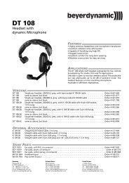
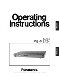
Control Knob (fig. 1)<br />
The single front panel control knob performs multiple<br />
functions;<br />
1. Rotate for Power ON/OFF<br />
2. Rotate for Audio Level<br />
3. Push quick, Channel Switching. (Also see page 9<br />
for special knob setup.)<br />
4. Push and rotate for Scan and<br />
Channel programming,<br />
Refer to the RECEIVER OPERATING INSTRUCTIONS<br />
for full details on how to use the single knob control for<br />
channel selection, scanning, and programming of the<br />
five memory locations.<br />
Figure 1 - R1a Control Panel<br />
LED Indicator (fig. 1)<br />
The three color LED indicator on the front panel provides<br />
multiple functions.<br />
CHANNEL NUMBER - The LED will blink OFF a<br />
number of times corresponding to the Channel Number<br />
when the unit is switched ON and also when a new frequency<br />
is added to an open channel. For example, for<br />
channel 3 the LED would blink OFF three times. After<br />
blinking the channel number the LED will return to a<br />
steady ON indicating normal operation.<br />
BATTERY STATUS – During normal operation, when<br />
the LED is GREEN, the battery is good. When the LED<br />
is YELLOW the battery is getting low. When the LED<br />
is RED, the battery is nearly depleted and should be<br />
replaced.<br />
PROGRAMMING FUNCTIONS - In the programming<br />
mode, the LED will blink at a fast rate to indicate<br />
scanning for an active frequency. It also flashes briefly<br />
to indicate a frequency has been programmed into a<br />
channel.<br />
4<br />
LECTROSONICS, INC.
IFB Receiver<br />
Headphone Jack (fig. 1 & fig. 2)<br />
On the front panel is a 3.5mm mini phone jack to accommodate<br />
a standard mono or stereo type 3.5 mm<br />
plug. The unit will drive low or high impedance earphones.<br />
The jack is also the receiver antenna input<br />
with the earphone cord acting as the antenna. The<br />
cord length is not critical but must be at least 6 inches<br />
minimum.<br />
Strain relief to avoid accidental disconnection can be<br />
provided with the included small hook and loop strip.<br />
Attach the adhesive strip side to the side of the receiver<br />
with the opening end of the strip up - place the cord in<br />
the strip and secure.<br />
Mono Plug/Stereo Plug Usage<br />
A Mono plug or a Stereo plug can be used with the<br />
IFBR1a headphone jack directly. When a Mono plug is inserted,<br />
a special circuit senses the “ring” to “sleeve” short<br />
and automatically switches off the ring to prevent excess<br />
battery drain. To reset, switch power OFF then back ON.<br />
Audio Level<br />
Headphones and ear pieces vary widely in sensitivity<br />
and impedance making it impossible to design a<br />
receiver with a fixed output power level that is correct<br />
for all situations. High impedance phones (600 to 2000)<br />
Ohms will have an inherently lower power level due<br />
to their high impedance and likewise low impedance<br />
phones may be extremely loud. CAUTION! Always set<br />
the Audio Level knob to minimum (counter-clockwise)<br />
when plugging phones into the jack, then adjust the<br />
knob for a comfortable audio level.<br />
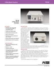
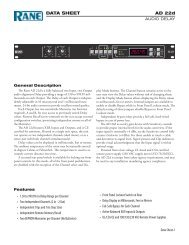
Frequency Adjust (fig.3)<br />
Two rotary switches adjust the center frequency of<br />
the carrier. The 1.6M is a coarse adjustment and the<br />
100K is the fine adjustment. Each transmitter is factory<br />
aligned at the center of its operating range. The default<br />
position of the frequency select switches is in the center<br />
of the transmitter’s range. The receiver and transmitter<br />
switches must be set to the same number/letter combination<br />
for proper operation.<br />
To gain access to these switches, slide the access door<br />
sideways with a fingernail.<br />
Figure 2 - Headphone cord strain relief<br />
0 1 2<br />
DE F 0 1<br />
E F 2<br />
3 D<br />
3<br />
C<br />
B<br />
4<br />
5<br />
C<br />
B<br />
4<br />
5<br />
A<br />
9 8<br />
6<br />
7<br />
A<br />
9 8<br />
6<br />
7<br />
Figure 3 - Frequency Adjustment<br />
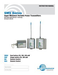
Figure 4 - R1a Block Diagram<br />
Rio Rancho, NM 5
R1a<br />
Receiver Normal Operation<br />
(already programmed)<br />
1. Set the Frequency of the receiver to match the<br />
frequency of the transmitter by using the two HEX<br />
rotary switches located on the side of the receiver<br />
under the sliding door. The 1.6M switch is for<br />
“coarse” adjustment (1.6 MHz per click) and the<br />
100k switch is for “fine” adjustment (0.1 MHz per<br />
click). Setting both to zero (0,0) is the low frequency<br />
end of the block and setting both to F (F,F) is the<br />
highest frequency end of the block.<br />
NOTE: Block 944 covers a special frequency<br />
range starting at 0,0 for 944.100 MHz through 4,E<br />
for 951.900 MHz for this limited band.<br />
2. Plug an earphone or headset into the 3.5mm jack.<br />
Be sure the unit has a good battery.<br />
3. Rotate the knob clockwise to switch the power ON<br />
(Do NOT hold the knob in while switching power<br />
ON). The LED will illuminate. Rotate the<br />
knob to set the desired audio level.<br />
4. If channel frequencies have been stored in the<br />
memory, change channels by pressing the knob<br />
briefly and release. The LED will blink the next<br />
channel number (frequency) and the receiver will<br />
resume operation on that channel. If no channel<br />
frequencies have been stored when pressing the<br />
knob to change channels, the LED will flash from<br />
green to red to yellow to green, indicating no stored<br />
channels and the unit will resume operation on<br />
the channel set by the switches.<br />
5. Whenever the power is switched ON, the unit defaults<br />
to the frequency set by the switches.<br />
Add a New Frequency to<br />
The Next Open Channel<br />
Before operating a receiver, one or more IFB T1 or T4<br />
transmitters must be placed in XMIT mode, with each<br />
transmitter set to the desired frequency and connected<br />
to a proper antenna, audio source, and power source.<br />
The transmitter frequency block must be the same as<br />
the receiver frequency block as marked on each unit.<br />
1. Position the receiver at a location within 20 to 100<br />
feet of the transmitter or transmitters.<br />
2. With the power ON, depress the knob until the LED<br />
starts rapidly blinking, then release the knob.<br />
3. The unit goes into program mode and does a scan/<br />
search. Previously programmed frequencies will<br />
be automatically skipped. When the unit stops on<br />
a new frequency audio from the transmitter will be<br />
heard in the earphone and the LED will stop blinking<br />
rapidly and will change to a slow blink mode.<br />
The unit is now waiting for an operator decision.<br />
You must now decide to either SKIP or STORE the<br />
frequency (step 4 or 5 below.) Switching the power<br />
to OFF without storing will delete the frequency.<br />
4. To SKIP the frequency, depress the knob briefly<br />
and the scan/search will resume.<br />
5. To STORE the frequency into a channel memory,<br />
depress the knob and hold it until the LED blinks<br />
the new channel number, then release the knob.<br />
The frequency is now stored in an open channel.<br />
6. The unit will continue scan/search for other frequencies.<br />
To store more frequencies repeat steps 4<br />
and 5 above. Up to 5 frequencies can be stored in<br />
memory channels.<br />
7. When all desired frequencies are stored switch the<br />
power to OFF for a few moments, then switch back<br />
to ON. The unit will default to the channel number<br />
set by the switches and resume normal operating<br />
mode.<br />
8. The first scan is made at low sensitivity and searches<br />
for only high level transmitter signals to avoid<br />
intermods. If the receiver does not stop on any<br />
frequency in the first scan, that means an IFB transmitter<br />
was not detected. In this condition the LED<br />
will change from a fast blink to a slow blink indicating<br />
the end of the scan. The complete scan should<br />
take 15 to 40 seconds.<br />
9. A second scan at high sensitivity is initiated by depressing<br />
the knob briefly at the end of the first scan<br />
to search for low level transmitter signals. When<br />
the scan stops and the transmitter audio is heard,<br />
either SKIP or STORE the frequency (step 4 or 5<br />
above).<br />
10. If the receiver still does not stop on any frequency,<br />
check that the transmitter is ON. Also, if a frequency<br />
is not received or received but distorted, some<br />
other signal may be interfering on that frequency.<br />
Change the transmitter to another frequency and<br />
try again.<br />
11. Switching the POWER to OFF during any mode<br />
simply terminates that mode and returns the unit to<br />
normal operating mode when the power is switched<br />
back to ON.<br />
Note: If knob does not change frequencies or<br />
begin scanning when pressed, check to see if its<br />
function has been changed - see instructions on<br />
page 9.<br />
6<br />
LECTROSONICS, INC.
IFB Receiver<br />
Erase All 5 Channel Memories<br />
1. With power OFF, depress the knob and turn the unit<br />
ON. Continue to hold the knob down until the LED<br />
starts rapidly blinking. The memory is now erased<br />
and the unit will go into scan/search mode.<br />
2. Continue from step 3 above - Add New Frequency.<br />
Multiple Transmitter Setup<br />
When using this IFB receiver in a search mode, with<br />
two or more transmitters running at the same time, the<br />
receiver may stop on a false signal under the following<br />
conditions:<br />
• Two transmitters are on and transmitting.<br />
• The distance from the transmitters to the IFB receiver<br />
is less than 5 feet.<br />
The false hits are caused by intermodulation or mixing<br />
in the front end of the IFB receiver. At a 5 to 10 foot<br />
distance, the two carriers are so strong at the receiver,<br />
that even this well designed front end will mix the carriers<br />
and produce phantom frequencies. The IFB receiver<br />
then halts its scan and stops on these false frequencies.<br />
All receivers will exhibit this type problem at some transmitter<br />
power level and range. You notice false signals<br />
more with a scanning mode receiver since it will find<br />
them all.<br />
Prevention is simple. Do one of the following:<br />
• Do the scan with only one transmitter on at a time.<br />
(Time consuming)<br />
• Increase the receiver to transmitter distance to at<br />
least 10 feet. (Preferred)<br />
Battery Instructions<br />
The battery you use in the R1a receiver should be a 9<br />
Volt alkaline or LiPolymer rechargeable type. Lithium<br />
batteries can also be used for extended operating time.<br />
An alkaline or LiPolymer battery will provide up to 8<br />
hours of operation and a lithium battery will provide up<br />
to 20 hours of operation. Carbon zinc batteries, even if<br />
marked “heavy duty” will only provide about 2 hours of<br />
operation.<br />
A green LED corresponds to a fresh battery. The LED<br />
will change to yellow for low battery warning then to red<br />
to indicate the need for a fresh battery.<br />
To replace the battery, open the bottom battery door<br />
cover with your thumb, rotate the door until it is perpendicular<br />
with the case and allow the battery to fall out of<br />
the compartment into your hand. It is difficult to install<br />
the battery backwards. Observe the large and small<br />
holes in the battery contact pad before inserting a new<br />
battery. Insert the contact end of the battery first, making<br />
sure the contacts are aligned with the holes in the<br />
contact pad, and then swing the door closed. You will<br />
feel it snap into place when it is fully closed.<br />
1<br />
To open the battery<br />
compartment door, push the<br />
door up and away from the case<br />
with your thumb, then swing<br />
open.<br />
2<br />
Figure 5 - Battery Replacement<br />
Rio Rancho, NM 7
R1a<br />
Troubleshooting<br />
Symptom<br />
LED not lit<br />
Possible Cause<br />
• Battery not installed or depleted<br />
• Power switch not on.<br />
NO SOUND IN HEADPHONE<br />
• AUDIO LEVEL turned all the way down.<br />
• Headphone plug not inserted fully.<br />
• Defective headphone<br />
• Transmitter not operating. (See separate transmitter <strong>manual</strong>.)<br />
• Receiver not on the same frequency as the transmitter.<br />
Refer to “Programming - Add a New Frequency” on page 6.<br />
DISTORTED SOUND<br />
• Transmitter gain (audio level) is far too high. Check mod level lamps<br />
on transmitter as it is being used. (Refer to Operating Instructions<br />
section in the transmitter <strong>manual</strong> for details on gain adjustment.)<br />
• Receiver output may be mismatched with the headset or<br />
earphone. Adjust Audio Level on receiver to the correct level<br />
for the headset or earphone.<br />
• Excessive wind noise or breath “pops.” Reposition microphone<br />
and/or use a larger windscreen.<br />
• Receiver may be tuned to an intermod. Reprogram the receiver.<br />
HISS AND NOISE, AUDIBLE DROPOUTS<br />
SHORT RANGE<br />
• Transmitter gain (audio level) far too low.<br />
• Receiver antenna missing or obstructed.<br />
(Headphone cable is the antenna.)<br />
• Transmitter antenna missing or obstructed.<br />
• Operating range too great.<br />
• Transmitter antenna obstructed<br />
• Receiver antenna (headset cord) may need to be repositioned for a<br />
line of sight to transmitter antenna<br />
• Receiver earphone cable is also the antenna. Make sure the cable<br />
is not coiled or wound up or wrapped around the receiver case.<br />
KNOB DOES NOT CHANGE FREQUENCIES NOR START SCANNING<br />
• Check to see if the knob function has been changed - see page 9.<br />
8<br />
LECTROSONICS, INC.
IFB Receiver<br />
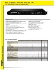
Replacement Parts and Accessories<br />
BEZELKIT<strong>R1A</strong> (full kit)<br />
Belt clip, bezel, sliding door, belt clip bumper,<br />
mounting screws<br />
BEZELKIT<strong>R1A</strong> (full kit)<br />
IFBR1-M000R<br />
Individual Parts:<br />
26377-1 Bezel<br />
25901 Sliding door<br />
IFBR1-M000R Belt clip assembly<br />
35747 Bumper for belt clip<br />
28528 Belt Clip Screw, 4-40 x 1/4 (1 req’d)<br />
28623 Bezel Screw, 2-56 x 5/16 (2 req’d)<br />
28528<br />
35856<br />
25901<br />
28623<br />
26377-1<br />
35747<br />
Knob Guard and related parts:<br />
35854 Hex key wrench<br />
28767 Spring washer<br />
26298-1 Knob guard<br />
28443 Spacer washer<br />
26297-1 Knurled knob<br />
28764 Set screws (2 req’d)<br />
35854<br />
Defeating the Frequency & Mode Switch<br />
In some instances, it may be beneficial to alter the knob<br />
setup so that the frequency change and mode functions<br />
are disabled. A common reason is to prevent the person<br />
wearing the receiver from accidentally pushing the button<br />
and disrupting the received signal.<br />
Use the following procedure to disable the knob:<br />
1) Use the allen wrench to loosen the set screw on the<br />
knob.<br />
2) Remove knob from shaft.<br />
3) Remove spacer washer (Part no. 28443) from hole<br />
in knob. Use caution - the washer is small and may<br />
fall out.<br />
4) Replace knob, making sure to slide the knob all the<br />
way onto the shaft.<br />
5) Tighten the set screw.<br />
The knob will be prevented from being depressed because<br />
it is resting against the knob guard.<br />
28767<br />
26298-1<br />
28443<br />
(knob) 26297-1<br />
(set screws) 28764<br />
Note: If you wish to change the frequency or<br />
mode and the knob is unable to be depressed,<br />
check to see if this procedure has aslready been<br />
done. You can temporarily enable the functions if<br />
you loosen the set screw, pull the knob out a small<br />
amount, tighten the set screw, and depress the<br />
knob. Then, reverse the procedure to disable the<br />
knob again. However, if youwish to permanently<br />
enable the knob, replace the spacer washer<br />
between the knob and the shaft.<br />
Rio Rancho, NM 9
R1a<br />
Specifications and Features<br />
Operating frequencies:<br />
Block 470 470.100 - 495.600<br />
Block 19 486.400 - 511.900<br />
Block 20 512.000 - 537.500<br />
Block 21 537.600 - 563.100<br />
Block 22 563.200 - 588.700<br />
Block 23 588.800 - 607.900 and 614.100 - 614.300<br />
Block 24 614.400 - 639.900<br />
Block 25 640.000 - 665.500<br />
Block 26 665.600 - 691.100<br />
Block 27 691.200 - 716.700 (export only)<br />
Block 28 716.800 - 742.300 (export only)<br />
Block 29 742.400 - 767.900 (export only)<br />
Block 944 944.100 - 951.900<br />
Number of frequencies: 256 per block (79 in block 944)<br />
Channel spacing:<br />
100 kHz<br />
Frequency control:<br />
Crystal Controlled Phase Locked Loop<br />
Sensitivity:<br />
1 uv (20 dB SINAD)<br />
Signal/Noise ratio:<br />
95 dB A-weighted<br />
Squelch quieting:<br />
90 dB<br />
AM rejection:<br />
50 dB, 10 uv to 100 mv<br />
Modulation acceptance:<br />
Spurious rejection:<br />
Third order intercept:<br />
Frequency response:<br />
Pilot tone:<br />
Audio output, headphone:<br />
Antenna: Headphone cable<br />
Programmable memory:<br />
Front panel controls:<br />
Indicators:<br />
Power requirement:<br />
Power consumption:<br />
±20 kHz<br />
Greater than 70 dB<br />
0 dBm<br />
100 Hz to 10 kHz, (±1db)<br />
29.997 kHz, 4.5 kHz deviation<br />
(fixed crystal controlled)<br />
1 Vrms into 50 ohms minimum<br />
5 frequencies<br />
Single knob controls Audio Output Level,<br />
Power on, programming and<br />
Scan Frequency Selection<br />
1 tricolor LED Indicator for power on, blinks to<br />
indicate channel number, blinks fast during scan,<br />
and turns yellow or red for low battery.<br />
Single 9V Alkaline Battery for approximately<br />
8 hours operation.<br />
60 ma.<br />
Allen wrench for knob: 0.035” (Lectro part number: 35854)<br />
Weight:<br />
7.3 oz with battery<br />
Size:<br />
3.6 x 2.4 x 0.8 inches<br />
Specifications subject to change without notice.<br />
10<br />
LECTROSONICS, INC.
IFB Receiver<br />
Service and Repair<br />
If your system malfunctions, you should attempt to correct or isolate the trouble before concluding that the equipment<br />
needs repair. Make sure you have followed the setup procedure and operating instructions. Check the interconnecting<br />
cables and then go through the Troubleshooting section in this <strong>manual</strong>.<br />
We strongly recommend that you do not try to repair the equipment yourself and do not have the local repair shop<br />
attempt anything other than the simplest repair. If the repair is more complicated than a broken wire or loose connection,<br />
send the unit to the factory for repair and service. Don’t attempt to adjust any controls inside the units. Once<br />
set at the factory, the various controls and trimmers do not drift with age or vibration and never require readjustment.<br />
There are no adjustments inside that will make a malfunctioning unit start working.<br />
LECTROSONICS’ Service Department is equipped and staffed to quickly repair your equipment. In warranty repairs<br />
are made at no charge in accordance with the terms of the warranty. Out-of-warranty repairs are charged at a modest<br />
flat rate plus parts and shipping. Since it takes almost as much time and effort to determine what is wrong as it does<br />
to make the repair, there is a charge for an exact quotation. We will be happy to quote approximate charges by phone<br />
for out-of-warranty repairs.<br />
Returning Units for Repair<br />
For timely service, please follow the steps below:<br />
A. DO NOT return equipment to the factory for repair without first contacting us by email or by phone. We need<br />
to know the nature of the problem, the model number and the serial number of the equipment. We also need a<br />
phone number where you can be reached 8 A.M. to 4 P.M. (U.S. Mountain Standard Time).<br />
B. After receiving your request, we will issue you a return authorization number (R.A.). This number will help speed<br />
your repair through our receiving and repair departments. The return authorization number must be clearly shown<br />
on the outside of the shipping container.<br />
C. Pack the equipment carefully and ship to us, shipping costs prepaid. If necessary, we can provide you with the<br />
proper packing materials. UPS is usually the best way to ship the units. Heavy units should be “double-boxed” for<br />
safe transport.<br />
D. We also strongly recommend that you insure the equipment, since we cannot be responsible for loss of or damage<br />
to equipment that you ship. Of course, we insure the equipment when we ship it back to you.<br />
<strong>Lectrosonics</strong> USA:<br />
Mailing address: Shipping address: Telephone:<br />
<strong>Lectrosonics</strong>, Inc. <strong>Lectrosonics</strong>, Inc. (505) 892-4501<br />
PO Box 15900 581 Laser Rd. (800) 821-1121 Toll-free<br />
Rio Rancho, NM 87174 Rio Rancho, NM 87124 (505) 892-6243 Fax<br />
USA<br />
USA<br />
Web:<br />
www.lectrosonics.com<br />
E-mail:<br />
sales@lectrosonics.com<br />
<strong>Lectrosonics</strong> Canada:<br />
Mailing Address: Telephone: E-mail:<br />
49 Spadina Avenue, (416) 596-2202 Sales: colinb@lectrosonics.com<br />
Suite 303A (877) 753-2876 Toll-free Service: joeb@lectrosonics.com<br />
Toronto, Ontario M5V 2J1 (877-7LECTRO)<br />
(416) 596-6648 Fax<br />
Rio Rancho, NM 11
LIMITED ONE YEAR WARRANTY<br />
The equipment is warranted for one year from date of purchase against defects in<br />
materials or workmanship provided it was purchased from an authorized dealer. This<br />
warranty does not cover equipment which has been abused or damaged by careless<br />
handling or shipping. This warranty does not apply to used or demonstrator equipment.<br />
Should any defect develop, <strong>Lectrosonics</strong>, Inc. will, at our option, repair or replace any<br />
defective parts without charge for either parts or labor. If <strong>Lectrosonics</strong>, Inc. cannot<br />
correct the defect in your equipment, it will be replaced at no charge with a similar new<br />
item. <strong>Lectrosonics</strong>, Inc. will pay for the cost of returning your equipment to you.<br />
This warranty applies only to items returned to <strong>Lectrosonics</strong>, Inc. or an authorized<br />
dealer, shipping costs prepaid, within one year from the date of purchase.<br />
This Limited Warranty is governed by the laws of the State of New Mexico. It states the<br />
entire liablility of <strong>Lectrosonics</strong> Inc. and the entire remedy of the purchaser for any<br />
breach of warranty as outlined above. NEITHER LECTROSONICS, INC. NOR<br />
ANYONE INVOLVED IN THE PRODUCTION OR DELIVERY OF THE EQUIPMENT<br />
SHALL BE LIABLE FOR ANY INDIRECT, SPECIAL, PUNITIVE, CONSEQUENTIAL,<br />
OR INCIDENTAL DAMAGES ARISING OUT OF THE USE OR INABILITY TO USE<br />
THIS EQUIPMENT EVEN IF LECTROSONICS, INC. HAS BEEN ADVISED OF THE<br />
POSSIBILITY OF SUCH DAMAGES. IN NO EVENT SHALL THE LIABILITY OF<br />
LECTROSONICS, INC. EXCEED THE PURCHASE PRICE OF ANY DEFECTIVE<br />
EQUIPMENT.<br />
This warranty gives you specific legal rights. You may have additional legal rights which<br />
vary from state to state.<br />
581 Laser Road NE • Rio Rancho, NM 87124 USA • www.lectrosonics.com<br />
(505) 892-4501 • (800) 821-1121 • fax (505) 892-6243 • sales@lectrosonics.com<br />
11 Feb 09