JVC DT-V24L1DU 24 inch Multi-Format LCD Monitor user ... - Talamas
JVC DT-V24L1DU 24 inch Multi-Format LCD Monitor user ... - Talamas
JVC DT-V24L1DU 24 inch Multi-Format LCD Monitor user ... - Talamas

You also want an ePaper? Increase the reach of your titles
YUMPU automatically turns print PDFs into web optimized ePapers that Google loves.
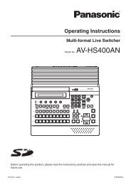
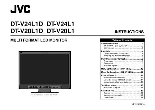
<strong>DT</strong>-V<strong>24</strong>L1D <strong>DT</strong>-V<strong>24</strong>L1<br />
<strong>DT</strong>-V20L1D <strong>DT</strong>-V20L1<br />
MULTI FORMAT <strong>LCD</strong> MONITOR<br />
The illustration of the monitor is of <strong>DT</strong>-V<strong>24</strong>L1D.<br />
INSTRUCTIONS<br />
Table of Contents<br />
Safety Precautions .............................................. 2<br />
IMPORTANT SAFEGUARDS ........................... 2<br />
Maintenance ..................................................... 3<br />
Installation ............................................................ 4<br />
Using the monitor on the stand ........................ 4<br />
Installing the monitor in the rack ....................... 5<br />
Daily Operations / Connections ......................... 6<br />
Front panel ....................................................... 6<br />
Rear panel ........................................................ 8<br />
Available signals ............................................... 9<br />
Menu Configuration—MAIN MENU .................. 10<br />
Menu Configuration—SET-UP MENU ............... 12<br />
External Control ................................................. 14<br />
About the external control .............................. 14<br />
Using the MAKE/TRIGGER system ................. 14<br />
Using the serial communication ..................... 15<br />
Troubleshooting ................................................. 16<br />
Self-check program ........................................ 16<br />
Specifications .................................................... 17<br />
General ........................................................... 17<br />
Input/output terminals ..................................... 17<br />
Dimensions ..................................................... 18<br />
LCT2202-001A
Safety Precautions<br />
WARNING: TO REDUCE RISK OF FIRE OR ELECTRIC SHOCK, DO NOT EXPOSE THIS APPARATUS TO<br />
RAIN OR MOISTURE. NO OBJECTS FILLED WITH LIQUIDS, SUCH AS VASES, SHALL BE<br />
PLACED ON THE APPARATUS.<br />
IMPORTANT SAFEGUARDS<br />
Electrical energy can perform many useful functions. This unit has been engineered and manufactured to assure<br />
your personal safety. But IMPROPER USE CAN RESULT IN POTENTIAL ELECTRIC SHOCK OR FIRE. In order<br />
not to defeat the safeguards incorporated into this product, observe the following basic rules for its installation,<br />
use, and service. Please read these “IMPORTANT SAFEGUARDS” carefully before use.<br />
• All the safety and operating instructions should be read before the product is operated.<br />
• The safety and operating instructions should be retained for future reference.<br />
• All warnings on the product and in the operating instructions should be adhered to.<br />
• All operating instructions should be followed.<br />
POWER CONNECTION<br />
The power supply voltage rating of this product is AC 120 V (For U.S.A. and Canada) and AC 220 – <strong>24</strong>0 V (For<br />
European countries, Asian countries, and United Kingdom).<br />
The power cord attached conforms to the following power supply voltage and countries. Use only the power<br />
cord designated to ensure safety and EMC regulations of each countries.<br />
Under the following conditions,<br />
1. Turn off the power.<br />
2. Unplug this product from the wall outlet.<br />
3. Refer service to qualified service personnel.<br />
a) When the product emits smoke or unusual<br />
smell.<br />
b) When the product exhibits a distinct change<br />
in performance —for example, no picture or no<br />
sound.<br />
c) If liquid has been spilled, or objects have fallen<br />
on the product.<br />
d) If the product has been exposed to rain or<br />
water.<br />
e) If the product has been dropped or damaged in<br />
any way.<br />
f) When the power supply cord or plug is<br />
damaged.<br />
2<br />
• Make enough room for inserting or removing the<br />
power plug. Place the product as close to an AC<br />
outlet as possible. The main power supply for the<br />
product is controlled by inserting or removing the<br />
power plug.<br />
• When you install the product in a place where<br />
you cannot easily insert or remove the power plug<br />
from an AC outlet, do not use the provided power<br />
cord holder, and insert or remove the power cord<br />
from the AC inlet on the product.<br />
• When the product is left unattended and unused<br />
for a long period of time, unplug it from the wall<br />
outlet and disconnect the cable system.<br />
• Do not overload wall outlets, extension cords, or<br />
convenience receptacles on other equipment as<br />
this can result in a risk of fire or electric shock.<br />
• Use only the accessory cord designed for this<br />
product to prevent shock.<br />
For U.S.A. and Canada: AC 120 V<br />
For European and Asian countries:<br />
AC 220 – <strong>24</strong>0 V<br />
For United Kingdom: AC 220 – <strong>24</strong>0 V<br />
This plug will fit only into a grounded power outlet. If you are unable to insert the plug into the outlet, contact<br />
your electrician to install the proper outlet. Do not defeat the safety purpose of the grounded plug.<br />
• This product should be operated only with the type of power source indicated on the label. If you are not sure<br />
of the type of power supply of your home, consult your product dealer or local electric power company.<br />
Warning:<br />
• Do not use the same power cord for AC 120 V as for AC 220 – <strong>24</strong>0 V. Doing so may cause malfunction,<br />
electric shock or fire.<br />
Note for United Kingdom power cord only<br />
The plug of United Kingdom power cord has a built-in fuse. When replacing the fuse, be sure to use only a<br />
correctly rated approved type, re-fit the fuse cover. (Consult your dealer or qualified personnel.)<br />
How to replace the fuse<br />
Open the fuse compartment with the blade screwdriver, and replace the fuse.<br />
U.S.A. only<br />
FCC NOTICE<br />
CAUTION: Changes or modifications not approved by <strong>JVC</strong> could void the <strong>user</strong>’s authority to operate the<br />
equipment.<br />
NOTE: This equipment has been tested and found to comply with the limits for a Class A digital device,<br />
pursuant to Part 15 of the FCC Rules. These limits are designed to provide reasonable protection against<br />
harmful interference when the equipment is operated in a commercial environment. This equipment<br />
generates, uses, and can radiate radio frequency energy and, if not installed and used in accordance with the<br />
instruction manual, may cause harmful interference to radio communications. Operation of this equipment in<br />
a residential area is likely to cause harmful interference in which case the <strong>user</strong> will be required to correct the<br />
interference at his own expense.<br />
Fuse<br />
• Do not install this product in the following places:<br />
– in a damp or dusty room<br />
– where the product is exposed to soot or steam, such as near the cooking counter or a humidifier<br />
– near heat sources<br />
– where condensation easily occurs, such as near the window<br />
• Do not place this product on an unstable cart, stand, or table. The product may fall, causing serious injury to<br />
a child or adult, and serious damage to the product.<br />
The product should be mounted according to the manufacturer’s instructions, and should use a mount<br />
recommended by the manufacturer.<br />
• Do not use this product near water.<br />
• Be sure to install the product in the place where proper temperature and humidity are kept (☞ “Operating<br />
conditions” on page 17).<br />
This product becomes hot during its use. Take enough care when handling the product.<br />
Do not attempt to service this product yourself, as<br />
opening or removing covers may expose you to<br />
dangerous voltages and other hazards. Refer all<br />
service to qualified service personnel.<br />
Do not use the product for a long time if the sound<br />
is distorted.<br />
• Slots and openings in the cabinet are provided<br />
for ventilation. These ensure reliable operation of<br />
the product and protect it from overheating. These<br />
openings must not be blocked or covered.<br />
• Never push objects of any kind into this product<br />
through openings as they may touch dangerous<br />
voltage points or short-circuit the parts, which<br />
could result in a fire or electric shock.<br />
• Never spill liquid of any kind on the product.<br />
• Do not put heavy objects on the product.<br />
• Do not step on or hang on the product.
• Before connecting other products such as VCR’s and personal computers, you should turn off the power of<br />
this product for protection against electric shock.<br />
• Do not use attachments not recommended by the manufacturer as they may be hazardous.<br />
• When replacement parts are required, be sure the service technician has used replacement parts<br />
specified by the manufacturer or equivalents. Unauthorized substitutions may result in fire, electric shock, or<br />
other hazards.<br />
• Upon completion of any service or repairs to this product, ask the service technician to perform safety<br />
checks to determine that the product is in proper operating condition.<br />
European Union only<br />
Dear Customer,<br />
This apparatus is in conformance with the valid European directives and standards regarding electromagnetic<br />
compatibility and electrical safety.<br />
European representative of Victor Company of Japan, Limited is:<br />
<strong>JVC</strong> Technology Centre Europe GmbH<br />
Postfach 10 05 52<br />
61145 Friedberg<br />
Germany<br />
Information for Users on Disposal of Old Equipment<br />
[European Union]<br />
This symbol indicates that the electrical and electronic equipment should not be disposed<br />
as general household waste at its end-of-life. Instead, the product should be handed over<br />
to the applicable collection point for the recycling of electrical and electronic equipment for<br />
proper treatment, recovery and recycling in accordance with your national legislation.<br />
European Union only<br />
EMC Supplement<br />
This equipment is in conformity with the provisions and protection requirements of the corresponding<br />
European Directives. This equipment is designed for professional video appliances and can be used in the<br />
following environments:<br />
• Controlled EMC environment (for example purpose built broadcasting or recording studio), and rural<br />
outdoors environment (far away from railways, transmitters, overhead power lines, etc.)<br />
In order to keep the best performance and ensure electromagnetic compatibility, we recommend to use cables<br />
not exceeding the following length:<br />
Cable<br />
Length<br />
Power cord (attached cable (H05VV-F 3 x 0.75 mm 2 )) 2.0 m<br />
Video signal cable (coaxial cable) 2.0 m<br />
Audio signal cable (shielded cable) 1.5 m<br />
DVI cable (shielded cable) 1.5 m<br />
RS-232C cable (shielded cable) 2.0 m<br />
(A straight cable with a D-sub 9-pin connector)<br />
RS-485 cable (twist pair cable) 2.0 m<br />
(A straight LAN cable)<br />
REMOTE cable (twist pair cable) 2.0 m<br />
(A straight LAN cable)<br />
The inrush current of this apparatus is 5.428 ampere.<br />
CAUTION<br />
In case where the strong electromagnetic waves or magnetism are near the audio cable or the signal cable,<br />
the sound or the picture will contain noise. In such cases, please keep the cable away from the sources of the<br />
disturbance.<br />
Maintenance<br />
Attention:<br />
This symbol is<br />
only valid in the<br />
European Union.<br />
By disposing of this product correctly, you will help to conserve natural resources and will<br />
help prevent potential negative effects on the environment and human health which could<br />
otherwise be caused by inappropriate waste handling of this product. For more information<br />
about collection point and recycling of this product, please contact your local municipal<br />
office, your household waste disposal service or the shop where you purchased the<br />
product.<br />
Penalties may be applicable for incorrect disposal of this waste, in accordance with<br />
national legislation.<br />
(Business <strong>user</strong>s)<br />
If you wish to dispose of this product, please visit our web page www.jvc-europe.com to<br />
obtain information about the take-back of the product.<br />
[Other Countries outside the European Union]<br />
If you wish to dispose of this product, please do so in accordance with applicable national<br />
legislation or other rules in your country for the treatment of old electrical and electronic<br />
equipment.<br />
Unplug this product from the wall outlet before<br />
cleaning.<br />
Screen<br />
To avoid irreparable change in appearance of the<br />
screen such as uneven color, discoloration, scratches,<br />
be careful about the following:<br />
• Do not paste or stick anything with any glues or<br />
adhesive tapes.<br />
• Do not write anything on the screen.<br />
• Do not strike the screen with a hard object.<br />
• Avoid condensation on the screen.<br />
• Do not wipe the screen with solvent such as alcohol,<br />
thinner, or benzine.<br />
• Do not wipe the screen hard.<br />
If the screen gets stained, wipe it with a soft dry cloth,<br />
a soft damp cloth, or a soft cloth soaked in waterdiluted<br />
neutral detergent and wrung well.<br />
Cabinet<br />
To avoid the deterioration or damages of the cabinet<br />
such as its paint’s peeling away, be careful about the<br />
following:<br />
• Do not wipe the cabinet using solvent such as<br />
alcohol, thinner, or benzine.<br />
• Do not expose the cabinet to any volatile substance<br />
such as insecticides.<br />
• Do not remain any rubber or plastic in contact for a<br />
long time.<br />
• Do not wipe the cabinet hard.<br />
Wipe stains off the cabinet with a soft cloth. If the<br />
cabinet gets heavily stained, wipe it with a soft cloth<br />
soaked in water-diluted neutral detergent and wrung<br />
well, then wipe with a soft dry cloth.<br />
Ventilation openings<br />
• Use a vacuum cleaner to get rid of the dust around<br />
the intakes (all the openings). If a vacuum cleaner<br />
is not available, use a cloth and wipe it off. Leaving<br />
the dust around the intakes may prevent proper<br />
temperature control and cause damage to the<br />
product.<br />
3
Installation<br />
CAUTION<br />
• Do not rest your arm on the monitor or lean against the monitor.<br />
• Do not hold the <strong>LCD</strong> panel when installing the monitor.<br />
• Make sure to install the monitor securely to prevent the monitor from falling over, which causes damage to the monitor or injury.<br />
7 Using the monitor on the stand<br />
You can place the monitor in the following two ways when using the monitor on the supplied stand.<br />
You can tilt the monitor from about 6° upward to<br />
about 6° downward.<br />
• When the monitor is not tilted (0°), the guidelines<br />
align as illustrated below.<br />
About 6°<br />
0°<br />
About 6°<br />
When the stand plate is attached to the higher<br />
position of the stand body (☞ “To adjust the stand<br />
height” on page 5), you can lift the stand up by about<br />
148° and place the monitor as illustrated below.<br />
• Remove the screws on the left and right sides of<br />
the stand (see the illustration below), then lift the<br />
stand up by about 148°.<br />
Make sure of attaching the removed screws after<br />
lifting up the stand.<br />
• To place the monitor as illustrated on the left again,<br />
remove the screws on the left and right sides of the<br />
stand, return the monitor angle to 0°, then attach<br />
the removed screws.<br />
Screw (silver)<br />
About 148°<br />
To detach the stand<br />
CAUTION<br />
• Lay the monitor on a cloth with the <strong>LCD</strong> panel facing down to prevent the <strong>LCD</strong> panel being damaged.<br />
Screw holes for<br />
stand attachment<br />
<strong>Monitor</strong><br />
Attachment screws<br />
Stand<br />
The illustration of the monitor is of <strong>DT</strong>-V<strong>24</strong>L1D.<br />
4<br />
Guidelines<br />
When installing the stand to the monitor, insert the guides of the stand into the guide holes<br />
on the monitor to place the stand on the correct position. Then fix the stand firmly with the<br />
attachment screws.<br />
Guide holes<br />
The illustration of the monitor is of <strong>DT</strong>-V<strong>24</strong>L1D.<br />
CAUTION<br />
• Be careful not to p<strong>inch</strong> your fingers in the gap between the<br />
monitor and the stand.<br />
• When the stand plate is attached to the lower position of<br />
the stand body (☞ “To adjust the stand height” on page 5),<br />
you cannot tilt the monitor downward.<br />
The illustrations of the monitor are of <strong>DT</strong>-V<strong>24</strong>L1D.<br />
CAUTION<br />
• When lifting up the stand, lay the monitor on a cloth with<br />
the <strong>LCD</strong> panel facing down to prevent the <strong>LCD</strong> panel being<br />
damaged.<br />
• Be careful not to p<strong>inch</strong> your fingers in the moving parts.<br />
• Make sure to lift the stand up until it stops (about 148°);<br />
otherwise the monitor may fall over.<br />
• Place the monitor on a mat to avoid scratching the table<br />
surface.<br />
• Do not place the monitor in this way when the stand plate<br />
is attached to the lower position of the stand body (☞ “To<br />
adjust the stand height” on page 5).<br />
<strong>Monitor</strong><br />
Screw holes for<br />
stand attachment<br />
(on the monitor)<br />
Screw holes for<br />
stand attachment<br />
(on the stand)<br />
Guides<br />
Stand
To adjust the stand height<br />
You can select the stand height—higher position or lower position.<br />
To change the stand height, change the position of the stand plate as illustrated below after detaching the stand<br />
from the monitor.<br />
• For detaching the stand, see “To detach the stand” on page 4.<br />
7 Installing the monitor in the rack<br />
Use a <strong>JVC</strong>’s RACK MOUNT ADAPTER (RK-C20L1; not supplied).<br />
CAUTION<br />
• Detach the stand first.<br />
• Ask your dealer to install.<br />
(<strong>DT</strong>-V20L1D and <strong>DT</strong>-V20L1 only)<br />
<br />
<br />
Screw holes for higher position<br />
Screw holes for lower position<br />
Stand plate<br />
Stand plate<br />
Stand body<br />
Stand body<br />
To prevent an accidental fall<br />
Fix the stand to a table or floor with M5 screws (not supplied).<br />
• Choose the screws of proper length corresponding to the thickness of the table or floor.<br />
<br />
Screw holes<br />
(See page 18 for the specifications of the screw holes.)<br />
The illustration of the monitor is of <strong>DT</strong>-V<strong>24</strong>L1D.<br />
Screw holes<br />
(See page 18 for the specifications of the screw holes.)<br />
5
Daily Operations / Connections<br />
7 Front panel<br />
<strong>DT</strong>-V<strong>24</strong>L1 and <strong>DT</strong>-V20L1 do not have u, SDI 1 and SDI 2 buttons/lamps (i).<br />
Tally lamp<br />
This lamp is controlled by the tally function<br />
of MAKE/TRIG. terminal (☞ “FUNCTION<br />
SETTING” on page 12 and “External<br />
Control” on page 14).<br />
NOTE<br />
“NO EFFECT” is displayed when you press a button which is not available for the current input or signal format (the lamp lights even when the function does not actually work).<br />
6<br />
The illustration of the monitor is of <strong>DT</strong>-V<strong>24</strong>L1D.<br />
1 Speakers (stereo)<br />
The speakers emit the same audio signal output<br />
from AUDIO ASSIGN (MONITOR OUT) terminals.<br />
☞ “8 AUDIO ASSIGN (MONITOR OUT) terminals”<br />
on page 8<br />
2 VOLUME adjustment knob<br />
Adjusts the speaker volume.<br />
3 PHASE adjustment knob<br />
Adjusts the picture hue.<br />
4 CHROMA adjustment knob<br />
Adjusts the picture color density.<br />
5 BRIGHT adjustment knob<br />
Adjusts the picture brightness.<br />
6 CONTRAST adjustment knob<br />
Adjusts the picture contrast.<br />
7 MUTING button<br />
Mutes the sound when a menu screen is not<br />
displayed.<br />
• To cancel the function, press the button again or<br />
turn the VOLUME adjustment knob.<br />
8 Menu select buttons ( ¥ ¥ ¥ )<br />
When a menu screen is displayed<br />
\ Selects or adjusts menu items.<br />
☞ “Menu Operations” on page 7<br />
When no menu screen is displayed<br />
\ Selects the audio channels of EMBEDDED<br />
AUDIO (<strong>DT</strong>-V<strong>24</strong>L1D and <strong>DT</strong>-V20L1D only).<br />
☞ “Audio Channel Selection” on page 7<br />
To display the set-up menu<br />
\ Press button while pressing button.<br />
☞ “Menu Operations” on page 7<br />
9 MENU button<br />
Displays the main menu.<br />
☞ “Menu Operations” on page 7<br />
p COLOR OFF button/lamp<br />
Displays only the luminance signal.<br />
q 1:1 button/lamp<br />
Displays the picture in the original resolution of the<br />
input signal.<br />
NOTE<br />
• This function does not work when the input video signal<br />
has higher resolution than the resolution of the panel<br />
(<strong>DT</strong>-V20L1D and <strong>DT</strong>-V20L1 only).<br />
• The aspect ratio of the picture may change depending on<br />
the input signal.<br />
w AREA MARKER button/lamp<br />
Activates/deactivates the settings of “MARKER<br />
SELECT,” “ASPECT SELECT,” “R-MARKER<br />
SELECT” and “R-ASPECT SELECT” in “AREA<br />
MARKER” (☞ page 10).<br />
NOTE<br />
• This function works when the picture is displayed in 16:9<br />
aspect ratio.<br />
• The functions do not work when “MARKER SELECT”<br />
or “R-MARKER SELECT” is set to “OFF” in “AREA<br />
MARKER.”<br />
e SAFETY MARKER button/lamp<br />
Activates/deactivates the settings of “ASPECT<br />
SELECT,” “R-ASPECT SELECT,” “SAFETY<br />
MARKER” and “R-SAFETY MARKER” in “AREA<br />
MARKER” (☞ 10 page).<br />
NOTE<br />
• This function does not work when displaying the picture<br />
in the 1:1 mode.<br />
• The functions do not work when “SAFETY MARKER”<br />
or “R-SAFETY MARKER” is set to “OFF” in “AREA<br />
MARKER.”<br />
r SCREENS CHECK button/lamp<br />
Displays only the selected element (R, G, or B) of<br />
the video signal.<br />
• Each time you press this button, the screen<br />
changes in the following order.<br />
Normal screen Red screen<br />
Blue screen<br />
Green screen<br />
• The screen changes as above also when “SCR<br />
CHECK” is controlled with MAKE/TRIGGER<br />
system (☞ “External Control” on page 14).<br />
t ASPECT button/lamp<br />
Changes the aspect ratio of the picture from 4:3 to<br />
16:9.<br />
• To return to 4:3, press the button again.<br />
• Use this function when the picture of 16:9 aspect<br />
ratio is squeezed into 4:3 format signal.<br />
NOTE<br />
This function does not work when displaying the picture in<br />
the 1:1 mode.<br />
y I / P MODE button/lamp<br />
Selects a proper mode corresponding to the input<br />
picture.<br />
• Each time you press the button, the mode<br />
changes as follows.<br />
• The mode changes as above also when<br />
“I / P MODE” is controlled with MAKE/TRIGGER<br />
system (☞ “External Control” on page 14).<br />
NOTE<br />
Memorized for each input.<br />
u T.C. (time code) button/lamp<br />
Displays the time data (time code) contained in the<br />
SDI signal.<br />
i INPUT SELECT buttons/lamps<br />
Selects an input.<br />
SDI 1 : HD/SD SDI (IN 1) terminal<br />
SDI 2 : HD/SD SDI (IN 2) terminal<br />
DVI<br />
: DVI-D (HDCP) terminal<br />
COMPO. / RGB : COMPO. / RGB terminal<br />
VIDEO 1 : VIDEO (INPUT 1) terminal<br />
VIDEO 2 : VIDEO (INPUT 2) terminal<br />
• The lamp for the selected input lights.<br />
o Power lamp<br />
Unlit<br />
: The monitor is completely<br />
off (the AC plug is not<br />
connected).<br />
Lights in Green : The monitor is on.<br />
Lights in orange : The monitor is off (standby).<br />
Flashes in orange : The monitor is in the suspend<br />
mode.<br />
; Standby button<br />
Turns on and off (standby) the monitor.<br />
NOTE<br />
To disconnect the mains line completely, unplug the AC<br />
plug from the wall outlet.
Menu Operations<br />
1 Display the menu.<br />
To display the main menu<br />
\ Press MENU button.<br />
To display the set-up menu<br />
\ Press button while pressing button.<br />
When the main menu is displayed<br />
Selected item<br />
Operation guide<br />
When the set-up menu is displayed<br />
Selected item<br />
Operation guide<br />
2 Press buttons to select an item,<br />
then press button.<br />
Ex.: When “AREA MARKER” is selected<br />
3 Press buttons to select an item,<br />
then press buttons to make<br />
adjustments.<br />
4 Press MENU button to return to the<br />
previous menu.<br />
• Pressing the button again finishes the menu<br />
operation.<br />
NOTE<br />
For some items, adjustments will be made by pressing<br />
in step 2 .<br />
Audio Channel Selection<br />
(<strong>DT</strong>-V<strong>24</strong>L1D and <strong>DT</strong>-V20L1D only)<br />
Select audio channels of EMBEDDED AUDIO<br />
signals to output from the speakers (L/R) and<br />
MONITOR OUT (L/R) terminals.<br />
1 Press or button to display the<br />
screen for audio channel selection.<br />
You cannot display this screen when displaying<br />
a menu screen.<br />
Selected item<br />
2 Press buttons to select the left<br />
(L) or right (R).<br />
3 Press buttons to select an<br />
audio channel.<br />
NOTE<br />
• You can select channels from 12 audio channels.<br />
• You have to choose a group of selectable audio<br />
channels before the channel selection (☞ “E.AUDIO<br />
GROUP” on page 11).<br />
4 Press MENU button to finish the<br />
audio channel selection.<br />
About the Status Display<br />
The monitor displays the status information below<br />
depending on the settings of the menu and buttons at<br />
the top of the screen.<br />
1 Audio level meter*<br />
• Not displayed when no EMBEDDED AUDIO<br />
signal is input or “LEVEL METER ch” is set to<br />
“OFF” (☞ “AUDIO SETTING” on page 11).<br />
2 Signal format<br />
• “NO SYNC” is displayed when no video signal is<br />
input.<br />
• “Out of range” is displayed for a noncompliant<br />
video signal input. When “COLOR SYSTEM” is<br />
set to “AUTO” (☞ “PICTURE FUNCTION” on<br />
page 11) and the noncompliant video signal is a<br />
composite one, “OTHERS” is displayed.<br />
3 Setting of “COLOR TEMP.”<br />
☞ “WHITE BALANCE SET.” on page 12<br />
• “*” is displayed at the end of the indication when<br />
“HIGH” or “LOW” is selected in “COLOR TEMP.”<br />
and its drive levels or cutoff points are adjusted.<br />
4 Displayed when “SYNC INPUT SEL.” is set to<br />
“EXT.” (external synchronization)<br />
☞ “ SYNC FUNCTION” on page 11<br />
5 Source name entered in “CHARACTER SET.”<br />
☞ “INFORMATION” on page 13<br />
• Displayed when “MONITOR NAME” is set to<br />
“ON” (☞ “INFORMATION” on page 13).<br />
• Displayed in large letters when “STATUS<br />
DISPLAY” is set to “OFF” or “AUTO” (☞<br />
“INFORMATION” on page 13).<br />
6 Time code*<br />
☞ “u T.C. (time code) button/lamp” on page 6<br />
• When the input signal includes no time code,<br />
“TC:– –:– –:– –:– –” is displayed.<br />
7 CRC error indication*<br />
☞ “CRC ERROR” in “INFORMATION” on page 13<br />
• A red square is displayed when an error occurs.<br />
* <strong>DT</strong>-V<strong>24</strong>L1D and <strong>DT</strong>-V20L1D only<br />
If you press INPUT SELECT button of the current<br />
input, the information below (2 – 4 and 8) is<br />
displayed in large letters for about three seconds.<br />
Then the status information on the left column<br />
(1 – 7) is displayed.<br />
When “STATUS DISPLAY” is set to “AUTO” or<br />
“ALWAYS”, the information below is also displayed in<br />
the cases below (☞ “INFORMATION” on page 13).<br />
• When you change the input<br />
• When the signal condition of the current input<br />
changes<br />
• When turn on the monitor<br />
8 Setting of “COMPO./RGB SEL.” or the signal<br />
form of DVI input<br />
☞ “COMPO./RGB SEL.” or “DVI INPUT SEL.” on<br />
page 10<br />
NOTE<br />
• When “STATUS DISPLAY” is set to “OFF” or “AUTO” (☞<br />
“INFORMATION” on page 13), 2 – 4 are not displayed at<br />
the top of the screen.<br />
• While displaying any of the status indications except 6 at<br />
the top of the screen, the picture is displayed below the<br />
status display area.<br />
7
Daily Operations / Connections (cont.)<br />
7 Rear panel<br />
<strong>DT</strong>-V<strong>24</strong>L1 and <strong>DT</strong>-V20L1 do not have 9 and p.<br />
AC inlet<br />
Power input connector. Connect the<br />
provided AC power cord to an AC outlet.<br />
• Attach the provided power cord holder<br />
to prevent accidental disconnection of<br />
the AC power cord (☞ the right).<br />
Security slot<br />
Install a security wire to this slot.<br />
The illustration of the monitor is of <strong>DT</strong>-V<strong>24</strong>L1D.<br />
CAUTION<br />
It is recommended not to use the power cord holder when installing the monitor in a monitor rack etc. where you cannot easily pull out the AC<br />
power cord from an AC outlet.<br />
Attaching the Power Cord Holder<br />
• The provided power cord holder prevents accidental disconnection of the AC power cord from the AC inlet.<br />
• The power cord holder consists of two parts, a case and a cover.<br />
1 Attach the power cord holder case<br />
around the AC inlet on the rear<br />
of the monitor with two screws<br />
(provided).<br />
CAUTION<br />
Use only the provided screws.<br />
2 Attach the power cord holder cover<br />
to the AC power cord.<br />
CAUTION<br />
A different plug shape will result in the cover<br />
being attached to a different position.<br />
3 Plug in the AC power cord<br />
to the AC inlet, and attach<br />
the power cord holder<br />
cover to the case.<br />
CAUTION<br />
Make sure the plug will not be<br />
pulled out after the cover is<br />
attached.<br />
NOTE<br />
To detach the cover, release<br />
the tab.<br />
Tab<br />
8<br />
1 REMOTE (MAKE/TRIG.) terminal (RJ-45)<br />
Terminal for controlling the monitor by an external control.<br />
☞ “External Control” on page 14<br />
2 REMOTE (RS-485) terminals (RJ-45)<br />
Terminals for controlling the monitor by an external control.<br />
☞ “External Control” on page 14<br />
3 REMOTE (RS-232C) terminal (D-sub 9-pin)<br />
Terminal for controlling the monitor by an external control.<br />
☞ “External Control” on page 14<br />
4 VIDEO (INPUT 1, INPUT 2) terminals (BNC)<br />
Input (IN) and output (OUT) terminals for the composite<br />
signals.<br />
5 COMPO./RGB (G/Y, B/PB/B-Y, R/PR/R-Y) terminals<br />
(BNC)<br />
Input (IN) and output (OUT) terminals for the analog<br />
component (color difference) or analog RGB signals.<br />
• Select the signal type in “COMPO./RGB SEL.”<br />
corresponding to the type of the input signal (☞ page 10).<br />
6 EXT.SYNC (CS) terminals (BNC)<br />
Input (IN) and output (OUT) terminals for the external<br />
composite sync (Cs) signals.<br />
• To use these terminals, set “SYNC INPUT SEL.” to “EXT.”<br />
☞ “SYNC FUNCTION” on page 11<br />
NOTE<br />
• The terminals are for all VIDEO (INPUT 1), VIDEO (INPUT 2) and<br />
COMPO./RGB.<br />
• When an external sync signal is input, external synchronization<br />
has priority over all VIDEO 1, VIDEO 2 and COMPO./RGB input.<br />
• The setting of “SYNC INPUT SEL.” is memorized for each input.<br />
7 AUDIO ASSIGN (IN 1, IN 2) terminals (pin jack)<br />
Input terminals for the analog audio signals.<br />
• Select the video input to assign the audio signal<br />
in “AUDIO1 ASSIGN.” or “AUDIO2 ASSIGN.” (☞<br />
“AUDIO SETTING” on page 11).<br />
8 AUDIO ASSIGN (MONITOR OUT) terminals (pin<br />
jack)<br />
Output terminals for the analog audio signal.<br />
• The terminals output the audio signal through AUDIO<br />
ASSIGN (IN 1) or AUDIO ASSIGN (IN 2) terminals<br />
when you select the video input you have selected<br />
for “AUDIO1 ASSIGN.” or “AUDIO2 ASSIGN.” in<br />
“AUDIO SETTING” (☞ page 11).<br />
• The EMBEDDED AUDIO signal is decoded into an<br />
analog signal, then emitted.<br />
NOTE<br />
• The signal is output from this terminal only when the monitor<br />
is on.<br />
• The EMBEDDED AUDIO signal has priority over the audio<br />
signal input to AUDIO ASSIGN (IN 1) or AUDIO ASSIGN (IN<br />
2) terminals when “SDI 1” or “SDI 2” is selected for “AUDIO1<br />
ASSIGN.” or “AUDIO2 ASSIGN.” and the EMBEDDED<br />
AUDIO signal is input to HD/SD SDI (IN 1) or HD/SD SDI<br />
(IN 2) terminal.<br />
9 HD/SD SDI (IN 1, IN 2) terminals (BNC)<br />
Input terminals for the HD SDI and SD SDI signals.<br />
The terminals accept the following signals.<br />
• SMPTE292M HD SDI signal<br />
• SMPTE259M SD SDI signal<br />
• EMBEDDED AUDIO signals* including up to 12 audio<br />
channels with the sampling frequency of 48 kHz.<br />
NOTE<br />
The types of signals coming through the IN 1 and IN 2 terminals<br />
are automatically recognized—HD SDI or SD SDI signal. Note,<br />
however, that input is not changed automatically.<br />
p HD/SD SDI (SWITCHED OUT) terminal (BNC)<br />
Output terminal for the HD SDI and SD SDI signals.<br />
• The SDI signal of the current input (SDI 1 or SDI 2) is<br />
re-clocked and output.<br />
NOTE<br />
• When the input other than SDI 1 or SDI 2 is selected, the SDI<br />
signal of the input selected last time is re-clocked and output from<br />
this terminal.<br />
• The signal is output from this terminal only when the monitor is<br />
on.<br />
q DVI-D (HDCP) terminal<br />
Input terminal for the DVI-D signal.<br />
• Select the signal type in “DVI INPUT SEL.” corresponding<br />
to the type of the input signal (☞ page 10).<br />
*Using the audio level meter (<strong>DT</strong>-V<strong>24</strong>L1D and <strong>DT</strong>-V20L1D only)<br />
You can check the conditions of the current EMBEDDED<br />
AUDIO signals in the audio level meter. The setting for the<br />
level meter is selected in “LEVEL METER SETTING” (☞<br />
“AUDIO SETTING” on page 11).
7 Available signals<br />
The following signals are available for this monitor.<br />
Video signals<br />
No.<br />
Signal name<br />
VIDEO<br />
(INPUT1, INPUT2)<br />
COMPO./RGB<br />
(Analog component/<br />
analog RGB)<br />
Input terminal<br />
HD/SD SDI (IN 1, IN 2)* 1<br />
(<strong>DT</strong>-V<strong>24</strong>L1D and<br />
<strong>DT</strong>-V20L1D only)<br />
DVI-D (HDCP)<br />
(Digital component/digital<br />
RGB)<br />
1 NTSC √ — — —<br />
2 PAL √ — — —<br />
3 SECAM √ — — —<br />
4 BW(50Hz/60Hz) √ — — —<br />
5 480/60i — √ √ —<br />
6 576/50i — √ √ —<br />
7 480/60p — √ — √<br />
8 576/50p — √ — √<br />
9 640∗480/60p — — — √<br />
10 720/60p — √ √ √<br />
11 720/50p — √ √ √<br />
12 720/30p — √ √ —<br />
13 720/25p — √ √ —<br />
14 720/<strong>24</strong>p — √ √ —<br />
15 1080/60i — √ √ √<br />
16 1035/60i — √* 2 √ —<br />
17 1080/50i — √ √ √<br />
18 1080/60p — — — √<br />
19 1080/50p — — — √<br />
20 1080/30p — √ √ √<br />
21 1080/25p — √ √ √<br />
22 1080/<strong>24</strong>p — √ √ √<br />
23 1080/30psF — √* 3 √* 3 —<br />
<strong>24</strong> 1080/<strong>24</strong>psF — √ √ —<br />
√ : Acceptable<br />
— : Not acceptable<br />
* 1 Compatible with EMBEDDED AUDIO<br />
* 2 Displays the picture as 1080/60i, and “1080/60i” is displayed in the status display (☞ page 7).<br />
* 3 “1080/60i” is displayed in the status display (☞ page 7).<br />
Computer signals (preset)<br />
DVI-D (HDCP) terminals<br />
No. Signal name<br />
Screen resolution<br />
Horizontal Vertical<br />
Horizontal Vertical frequency (kHz) frequency (Hz)<br />
Scan system<br />
1 VGA60 640 480 31.5 59.9 Non-interlace<br />
2 WVGA60 852 480 31.5 59.9 Non-interlace<br />
3 SVGA60 800 600 37.9 60.3 Non-interlace<br />
4 XGA60 10<strong>24</strong> 768 48.4 60.0 Non-interlace<br />
5 WXGA (1280) 1280 768 47.8 60.0 Non-interlace<br />
6 SXGA60 1280 10<strong>24</strong> 64.0 60.0 Non-interlace<br />
7 SXGA+60 1400 1050 64.0 60.0 Non-interlace<br />
8 SXGA+60* 1400 1050 65.2 60.0 Non-interlace<br />
9 WSXGA+60 1680 1050 65.2 60.0 Non-interlace<br />
10 UXGA60* 4 1600 1200 75.0 60.0 Non-interlace<br />
11 WUXGA60* 4 1920 1200 74.0 59.9 Non-interlace<br />
Specification of DVI-D (HDCP) terminal<br />
Connect it to DVI-D output terminal on a personal computer.<br />
Pin<br />
No.<br />
Input signal<br />
Note for analog component/analog RGB signals<br />
The monitor is compatible with G on sync, Y on sync and composite sync (Cs) signals. The monitor is not<br />
compatible with separate sync (HS/VS) signals.<br />
Note for computer signals<br />
• Non-preset signals may not be displayed normally even if its frequency is within the acceptable range.<br />
• When a preset signal is input, the signal format is displayed on the screen. For other signals, the resolution is<br />
displayed.<br />
Note for connections<br />
• Before making any connections, turn off all the equipment.<br />
• Use a cord whose plugs correctly match the terminals on this monitor and the equipment.<br />
• Plugs should be firmly inserted; poor connections could cause noise.<br />
• When unplugging a cord, be sure to grasp its plug and pull it out.<br />
• DO NOT connect the power cord until all connections are completed.<br />
• Refer also to the <strong>user</strong> manual of each piece of equipment.<br />
Pin<br />
No.<br />
Input signal<br />
Pin<br />
No.<br />
Input signal<br />
1 T.M.D.S Data 2– 9 T.M.D.S Data 1– 17 T.M.D.S Data 0–<br />
2 T.M.D.S Data 2+ 10 T.M.D.S Data 1+ 18 T.M.D.S Data 0+<br />
3 T.M.D.S Data 2 shield 11 T.M.D.S Data 1 shield 19 T.M.D.S Data 0 shield<br />
4 NC 12 NC 20 NC<br />
5 NC 13 NC 21 NC<br />
6 DDC Clock 14 +5 V Power 22 T.M.D.S Clock shield<br />
7 DDC Data 15 GND 23 T.M.D.S Clock+<br />
8 NC 16 Hot Plug Detect <strong>24</strong> T.M.D.S Clock–<br />
* 4 For <strong>DT</strong>-V20L1D and <strong>DT</strong>-V20L1: When No. 10 or 11 signal is input, thin lines will become obscured because their signal<br />
resolution is higher than the screen resolution.<br />
9
Menu Configuration—MAIN MENU<br />
For the operation procedure, see page 7.<br />
Operation guide<br />
Shows the buttons for<br />
each operation.<br />
NOTE<br />
• The menu automatically disappears in about 30 seconds after the last menu operation.<br />
• Some items may not appear on the menu depending on the input or the input signal. These items are not available.<br />
Technical information<br />
Setting of “MARKER SELECT” and “R-MARKER SELECT”<br />
The setting values and features are as follows.<br />
OFF : “MARKER SELECT” and “R-MARKER SELECT” do not function.<br />
LINE : Displays the area with an outline.<br />
HALF : The area outside the specified aspect ratio of the screen is displayed as a 50% transparency.<br />
HALF+L : The area of the specified aspect ratio of the screen is indicated by an outline, and the area<br />
outside of that is displayed as a 50% transparency.<br />
BLK. : The area outside the specified aspect ratio of the screen is black. Only the portion of the picture<br />
within the designated area is displayed.<br />
BLK. +L : The area of the specified aspect ratio of the screen is indicated by an outline, and the area<br />
outside of that becomes black so that only the area inside the line is displayed.<br />
PICTURE IMPROVEMENT<br />
10<br />
Setting for the picture quality<br />
Item To do Setting value<br />
MOVING<br />
Reduce the lag of moving pictures which is peculiar to <strong>LCD</strong>. OFF, ON<br />
PICTURE* 1<br />
APERTURE Select the frequency of the luminance signal compensated in<br />
OFF, LOW, HIGH<br />
FREQ.* 2<br />
“APERTURE LEVEL.”<br />
APERTURE Compensate the frequency response of the luminance signal of the 01 – 10<br />
LEVEL* 2<br />
video signal.<br />
CTI* 2 Adjust the clearness of the outlines of the chrominance signal. OFF, NORMAL, HARD<br />
LTI* 2 Adjust the clearness of the outlines of the luminance signal. OFF, NORMAL, HARD<br />
sub menu Display the sub menu which enables you to adjust the items of “PICTURE IMPROVEMENT” while<br />
viewing the actual picture.<br />
reset<br />
Restore the default settings for all the items in “PICTURE IMPROVEMENT.”<br />
BACK LIGHT Setting value: –20 – 00 – +20<br />
Adjusts the brightness of the display.<br />
DVI INPUT SEL. Setting value: AUTO, COMPO. (component), RGB<br />
Selects the signal type you want to use for DVI-D (HDCP) terminal.<br />
NOTE<br />
• DVI-D input of the monitor is compatible with HDCP.<br />
• Select “COMPO.” or “RGB” when the signal is not recognized correctly with “AUTO.”<br />
COMPO./RGB SEL. Setting value: COMPO. (component), RGB<br />
Selects the signal type you want to use for COMPO./RGB terminals.<br />
AREA MARKER* 2<br />
Setting for AREA MARKER functions<br />
Item To do Setting value<br />
MARKER<br />
SELECT<br />
Select the style of AREA MARKER whose aspect ratio is selected in “ASPECT<br />
SELECT.”<br />
☞ “Technical<br />
information”<br />
ASPECT<br />
SELECT<br />
Select the aspect ratio of AREA MARKER. You can display this AREA<br />
MARKER with AREA MARKER button on the front panel (☞ page 6) or by<br />
4:3, 14:9, 13:9, 2.35:1,<br />
1.85:1, 1.66:1<br />
using external control (☞ page 14).<br />
SAFETY Adjust the size of SAFETY AREA within the area marked with AREA MARKER. OFF, 80% – 100%<br />
MARKER This AREA MARKER’s aspect ratio is selected in “ASPECT SELECT.”<br />
R-MARKER<br />
SELECT<br />
Select the style of AREA MARKER whose aspect ratio is selected in<br />
“R-ASPECT SELECT.”<br />
☞ “Technical<br />
information”<br />
R-ASPECT<br />
SELECT<br />
R-SAFETY<br />
MARKER<br />
Select the aspect ratio of AREA MARKER. You can display this AREA<br />
4:3, 14:9, 13:9, 2.35:1,<br />
MARKER by using external control (☞ page 14).<br />
1.85:1, 1.66:1<br />
Adjust the size of SAFETY AREA within the area marked with AREA MARKER. OFF, 80% – 100%<br />
This AREA MARKER’s aspect ratio is selected in “R-ASPECT SELECT.”<br />
NOTE<br />
• To set up non-“R-” items, press AREA MARKER or SAFETY MARKER button. An external control system should not be<br />
operated at this time.<br />
• Using the external control, you can select either “R-” items or non-“R-” items to activate (☞ “External Control” on page 14).<br />
• When a picture is displayed in 4:3 aspect ratio, SAFETY AREA for the 4:3 area is displayed.<br />
• To display SAFETY AREA for the area of a picture displayed in 16:9 aspect ratio, set “MARKER SELECT” and “R-MARKER<br />
SELECT” to “OFF.”<br />
* 1 <strong>DT</strong>-V<strong>24</strong>L1D and <strong>DT</strong>-V<strong>24</strong>L1 only<br />
* 2 Memorized for each input.
PICTURE FUNCTION<br />
Setting for the screen display<br />
Item To do Setting value<br />
sub menu POSI. Select the contents and displaying position of “sub menu.” ☞ “Technical information”<br />
COLOR SYSTEM Select the color system.<br />
• If the picture is unstable with “AUTO,” select the appropriate<br />
color system other than “AUTO.”<br />
AUTO, NTSC, PAL, SECAM<br />
Operation guide<br />
Shows the buttons for<br />
each operation.<br />
NOTE<br />
• The menu automatically disappears in about 30 seconds after the last menu operation.<br />
• Some items may not appear on the menu depending on the input or the input signal. These items are not available.<br />
Technical information<br />
Setting of “sub menu POSI.”<br />
The setting values and features are as follows.<br />
LOWER1 : Displays the current setting and adjustment bar at the lower part of the screen.<br />
UPPER1 : Displays the current setting and adjustment bar at the upper part of the screen.<br />
LOWER2 : Displays the current setting at the lower part of the screen.<br />
UPPER2 : Displays the current setting at the upper part of the screen.<br />
NOTE<br />
The adjustment bar is not displayed for some items.<br />
Setting of “E.AUDIO GROUP”<br />
The setting values and selectable audio channels of EMBEDDED AUDIO are as follows.<br />
1G : channel(s) 1/2/3/4/1+2/3+4/1 – 4 (1G)<br />
2G : channel(s) 5/6/7/8/5+6/7+8/5 – 8 (2G)<br />
1-2G : channel(s) 1/2/3/4/5/6/7/8/1+2/3+4/5+6/7+8/1 – 4 (1G)/5 – 8 (2G)/1 – 8 (1G+2G)<br />
3G : channel(s) 9/10/11/12/9+10/11+12/9 – 12 (3G)<br />
1-3G : channel(s) 1/2/3/4/5/6/7/8/9/10/11/12/1+2/3+4/5+6/7+8/9+10/11+12/1 – 4 (1G)/5 – 8 (2G)/9 – 12 (3G)/1<br />
– 8 (1G+2G)/1 – 12 (1-3G)<br />
Example of the level meter display —Level indication and audio channels<br />
Ex.: When “LEVEL METER ch” is set to “12:78” and ”BAR TYPE” is set to “3COLORS.”<br />
NOTE<br />
• When “BAR TYPE” is set to “W.100,” the standard input level<br />
set in the “REFERENCE LEVEL” is displayed with the line<br />
indication. The input level set in “OVER LEVEL” is not displayed.<br />
• The audio channel bar with no signal input is displayed in white<br />
for “3COLORS,” and in gray for “W.100.”<br />
OVER LEVEL<br />
REFERENCE LEVEL<br />
Red<br />
Yellow<br />
Green<br />
AUDIO SETTING<br />
Setting for the audio input/output<br />
Item To do Setting value<br />
BALANCE Adjust the balance between the right and left L5 – L1, 0, R1 – R5<br />
speakers.<br />
AUDIO1 ASSIGN. Select the video input which the audio signal<br />
through AUDIO ASSIGN (IN 1) terminal is<br />
SDI-1* 1 , SDI-2* 1 , DVI, COMP/RGB, VIDEO-1,<br />
VIDEO-2<br />
assigned to.<br />
AUDIO2 ASSIGN. Select the video input which the audio signal<br />
through AUDIO ASSIGN (IN 2) terminal is<br />
assigned to.<br />
E.AUDIO Select the audio channel group of the<br />
☞ “Technical information”<br />
GROUP* 1, 2 EMBEDDED AUDIO signals.<br />
LEVEL METER<br />
SETTING* 1, 2<br />
Adjust the audio level meter display for the EMBEDDED AUDIO signals (☞ “Technical<br />
information”).<br />
LEVEL<br />
METER ch<br />
Select the audio channels used in the audio<br />
level meter display.<br />
OFF, 12:78 (Displays the channels 1 – 6 at the<br />
top left of the screen and 7 – 12 at the top right.),<br />
13:<strong>24</strong> (Displays the odd channels at the top left<br />
of the screen and the even channels at the top<br />
right.)<br />
BAR TYPE Select the color of the audio level meter display. 3COLORS (3 colors to indicate variations in<br />
input levels), W.100 (white)<br />
REFERENCE Select the standard input level.<br />
–20dB, –18dB<br />
LEVEL<br />
OVER LEVEL Select the input level’s lower limit indicated in<br />
red for the “3COLORS” display.<br />
–10dB, –8dB, –6dB, –4dB, –2dB<br />
BAR<br />
BRIGHTNESS<br />
Select the brightness of the audio level meter<br />
display.<br />
HIGH, LOW<br />
NOTE<br />
• When selecting “BALANCE,” the adjustment bar is displayed at the lower part of the screen.<br />
• You cannot select the same input for both “AUDIO1 ASSIGN.” and “AUDIO2 ASSIGN.”<br />
SYNC FUNCTION<br />
Setting for the synchronization with signals<br />
Item To do Setting value<br />
NO SYNC ACTION Select the screen status when no signal is being<br />
input.<br />
OFF, SUSPEND (suspend mode),<br />
GRAY B.(gray screen)<br />
DELAY TIME Select the period until the screen status 5sec., 20sec., 1min., 15min., 30min.<br />
changes after signals stop coming in.<br />
SYNC INPUT SEL.* 2 Select the sync signal for the VIDEO and INT., EXT.<br />
COMPO./RGB input.<br />
QUICK SWITCHING Select the quickness for switching the input. STD., QUICK<br />
* 1 <strong>DT</strong>-V<strong>24</strong>L1D and <strong>DT</strong>-V20L1D only<br />
* 2 Memorized for each input.<br />
11
Menu Configuration—SET-UP MENU<br />
For the operation procedure, see page 7.<br />
Operation guide<br />
Shows the buttons for<br />
each operation.<br />
FUNCTION SETTING<br />
Setting for the tally lamp<br />
Item To do Setting value<br />
TALLY SELECT Select the color of the tally lamp on the upper front panel. GREEN, RED<br />
TALLY BLINK Select the blinking time of the tally lamp till it gets lighting. OFF, 5sec., 8sec.<br />
12<br />
NOTE<br />
The tally lamp is controlled using MAKE/TRIG. terminal of REMOTE terminals (☞ “External Control” on page 14).<br />
PICTURE SUB ADJ.<br />
Adjusts the standard level for the picture adjustment and selects the set-up level for the input video signal.<br />
Item To do Setting value<br />
CONTRAST* 1 Adjust the standard level for the contrast adjusted with –20 – 00 – +20<br />
CONTRAST knob on the front panel.<br />
BRIGHT* 1 Adjust the standard level for the brightness adjusted with –20 – 00 – +20<br />
BRIGHT knob on the front panel.<br />
CHROMA* 1 Adjust the standard level for the chroma adjusted with –20 – 00 – +20<br />
CHROMA knob on the front panel.<br />
PHASE* 1 Adjust the standard level for the phase adjusted with –20 – 00 – +20<br />
PHASE knob on the front panel.<br />
NTSC SETUP* 1 Select the set-up level of the input NTSC signal. 00 (compliant with 0% set-up signal), 7.5<br />
(compliant with 7.5% set-up signal)<br />
COMPO. LEVEL Select the level of the analog component signal. SMPTE (compliant with M2VTR signals),<br />
B75 (compliant with BetacamVTR 7.5%<br />
set-up signal), B00 (compliant with<br />
BetacamVTR 0% set-up signal)<br />
sub menu Display the sub menu which enables you to adjust the items in “PICTURE SUB ADJ.” while viewing<br />
the actual picture.<br />
reset<br />
Restore the default settings for all the items in “PICTURE SUB ADJ.”<br />
SIZE/POSI. ADJ.<br />
Adjusts the size and position of the picture.<br />
Item To do Setting value<br />
H SIZE* 2<br />
Adjust the horizontal picture size.<br />
H POSITION* 2 Adjust the horizontal picture position.<br />
Varies depending on the other<br />
V SIZE* 2<br />
Adjust the vertical picture size.<br />
settings.<br />
V POSITION* 2 Adjust the vertical picture position.<br />
sub menu Display the sub menu which enables you to adjust the items of “SIZE/POSI. ADJ.” while viewing<br />
the actual picture.<br />
reset<br />
Restore the default settings for all the items in “SIZE/POSI. ADJ.”<br />
NOTE<br />
• The menu automatically disappears in about 30 seconds after the last menu<br />
operation.<br />
• Some items may not appear on the menu depending on the input or the input<br />
signal. These items are not available.<br />
WHITE BALANCE SET.<br />
Selects the color temperature and adjusts the drive level and cutoff point of each color (R/G/B).<br />
Item To do Setting value<br />
COLOR TEMP. Select the color temperature. HIGH(9300), LOW(6500), OTHER<br />
R DRIVE, G DRIVE, Adjust the drive level of each color (red, green, and blue). MIN – 000 – MAX (in 256 grades)<br />
B DRIVE* 3<br />
R CUT OFF, G CUT Adjust the cutoff point of each color (red, green, and blue). MIN – 000 – MAX (in 256 grades)<br />
OFF, B CUT OFF* 3<br />
sub menu<br />
Display the sub menu which enables you to adjust the items in “WHITE BALANCE SET.” while<br />
viewing the actual picture.<br />
reset<br />
Restore the default settings for the drive levels and cutoff points of the selected color<br />
temperature.<br />
* 1 Memorized for each input.<br />
* 2 Memorized for each signal format.<br />
* 3 Memorized for each color temperature (HIGH, LOW, OTHER).
Operation guide<br />
Shows the buttons for<br />
each operation.<br />
NOTE<br />
• The menu automatically disappears in about 30 seconds after the last menu operation.<br />
• Some items may not appear on the menu depending on the input or the input signal. These items are not available.<br />
Technical information<br />
Using “CHARACTER SET.”<br />
Enter a name for an input video source following the steps below.<br />
1 Select “CHARACTER SET.”<br />
2 Press buttons to select the first character.<br />
• Each time you press button, the character changes as follows. Press button to reverse the order.<br />
Space<br />
3 Press button to move the arrow to the next.<br />
REMOTE SETTING (☞ “External Control” on pages 14 and 15)<br />
Setting for the external control<br />
Item To do Setting value<br />
RS REMO SEL Select the input terminal used for an RS232C, RS485<br />
external control.<br />
PARA REMO SEL Select the external control method for MAKE, TRIGGER, SET<br />
MAKE/TRIG. terminal.<br />
PORT F1, PORT F2,<br />
PORT F3, PORT F4,<br />
PORT F5, PORT F6<br />
Assign the control functions to the pins<br />
of MAKE/TRIG. terminal (1 to 6) when<br />
selecting “SET” in “PARA REMO SEL.”<br />
COLOR OFF, ASPECT, A.MARKER, S.MARKER,<br />
TIME CODE* 1 , 1:1, SCR CHECK, I/P MODE,<br />
SDI 1* 1 , SDI 2* 1 , DVI, COMP./RGB, VIDEO 1,<br />
VIDEO 2, EXT.SYNC, TALLY, TALLY SEL, MONI.<br />
NAME, MUTING, MARK.SEL, L.METER* 1 ,<br />
STATUS, – – – (no function)<br />
INFORMATION<br />
Setting for the information display of the monitor<br />
Item To do Setting value<br />
MONITOR NAME Choose if the name entered in “CHARACTER SET.” is displayed on OFF, ON<br />
the screen (☞ “About the Status Display” on page 7).<br />
CHARACTER SET.* 2 Enter an optional name for an input video source (10 characters at<br />
maximum).<br />
☞ “Technical<br />
information”<br />
STATUS DISPLAY Choose if the information of the current input is displayed on the AUTO, OFF, ALWAYS<br />
screen (☞ “About the Status Display” on page 7).<br />
CRC ERROR* 1 Choose if the CRC error indication for the input HD SDI signal is OFF, ON<br />
displayed on the screen (☞ “About the Status Display” on page 7).<br />
SUB HOUR METER Display the total hours of use (unit: hour). You can reset this HOUR METER.<br />
MODEL<br />
Display the model name of the monitor.<br />
VERSION<br />
Display the version of the monitor.<br />
HOUR METER Display the total hours of use (unit: hour). This item is used for maintenance of the monitor. You<br />
cannot reset this HOUR METER.<br />
CONTROL LOCK Setting value: OFF, ON<br />
Turns on (or off) the control lock function to disable the buttons on the front panel.<br />
NOTE<br />
The following operations are available even though this function is activated.<br />
– Turning on/off the monitor<br />
– Displaying the set-up menu (by pressing button while pressing button) and turning “CONTROL LOCK” to “OFF”<br />
– Operating the monitor by an external control<br />
If you try other operations, “ Control lock on!” appears on the screen.<br />
all reset<br />
Restores all the settings and adjustments of the monitor to the default.<br />
NOTE<br />
• “HOUR METER” and the settings done by using the adjustment knobs on the front panel will not be reset.<br />
• After performing “all reset,” the monitor is turned off then turned on automatically.<br />
* 1 <strong>DT</strong>-V<strong>24</strong>L1D and <strong>DT</strong>-V20L1D only<br />
* 2 Memorized for each input.<br />
4 Repeat steps 2 and 3 (10 characters at maximum).<br />
5 Press MENU button to store the source name.<br />
13
External Control<br />
7 About the external control<br />
This monitor has three external control terminals.<br />
• MAKE/TRIG. terminal : The following external control systems are available.<br />
(1) MAKE (make contact system) : Controls the function by short-circuiting the corresponding pin terminal to<br />
the GND pin terminal, or disconnecting (opening) it (☞ the right).<br />
(2) TRIGGER (trigger system) : Controls the function by inputting the pulse signal instantaneously to the<br />
corresponding pin terminal (☞ the right).<br />
• RS-232C terminal : Controls the monitor with RS-232C system. (☞ “Using the serial communication”<br />
on page 15)<br />
• RS-485 terminals : Controls the monitor with RS-485 system. (☞ “Using the serial communication” on<br />
page 15)<br />
Set the following items of “REMOTE SETTING” in set-up menu according to the external control terminal and<br />
control system you use (☞ page 13).<br />
Control system “RS REMO SEL” setting “PARA REMO SEL” setting<br />
MAKE — MAKE<br />
TRIGGER — TRIGGER<br />
Serial<br />
RS-485 RS485 *1 —<br />
communication<br />
RS-232C RS232C *1 —<br />
* 1 On the monitor connected to the personal computer etc, select the terminal the equipment actually connected to. On the<br />
other monitors, select “RS485.”<br />
NOTE<br />
• Control priority is as follows.<br />
MAKE > TRIGGER, serial communication, and buttons on the monitor<br />
• You can use the external control even when “CONTROL LOCK” is set to “ON” (☞ page 13).<br />
<br />
You can control the monitor by a personal computer or dedicated controller* 2 . For the details, see the right.<br />
* 2 The controller is not commercially available. Consult your dealer if you need it.<br />
<br />
7 Using the MAKE/TRIGGER system<br />
MAKE/TRIG. terminal is configured as follows. You can assign a function to each pin terminal in “REMOTE<br />
SETTING” (☞ “PORT F1” – “PORT F6” on page 13).<br />
This is a female<br />
terminal.<br />
Pin No. Pin name Pin No. Pin name<br />
1 PORT F1 5 PORT F5<br />
2 PORT F2 6 PORT F6<br />
3 PORT F3 7 External control* 3<br />
4 PORT F4 8 GND<br />
* 3 The external control (the 7th pin terminal) must be controlled by the MAKE (make contact) system.<br />
To assign the functions to the pin terminals<br />
For the operation procedure, see page 7.<br />
1 Select “REMOTE SETTING” on the set-up menu.<br />
2 Set “PARA REMO SEL” to “SET.”<br />
3 Select a pin name (“PORT F1” – “PORT F6”) which you want to assign a function to, then select the function<br />
you want to assign.<br />
• For selectable functions, see the tables below.<br />
Functions controlled by MAKE/TRIGGER system<br />
14<br />
Display Functions to be controlled Opening<br />
Shortcircuiting<br />
COLOR OFF Color off Color Monochrome<br />
ASPECT Changes the aspect ratio. 4:3 16:9<br />
A.MARKER AREA MARKER display Off On<br />
S.MARKER SAFETY MARKER display Off On<br />
TIME CODE* 4 Time code display Off On<br />
1:1 Displays in 1:1 mode. Off On<br />
SCR CHECK Screen check* 5 ☞ “r SCREENS<br />
CHECK button/lamp”<br />
on page 6<br />
I/P MODE I/P MODE* 5 ☞ “y I / P MODE<br />
button/lamp” on page 6<br />
SDI 1* 4 Changes the input to “SDI 1.” Invalid Valid<br />
SDI 2* 4 Changes the input to “SDI 2.” Invalid Valid<br />
DVI Changes the input to “DVI.” Invalid Valid<br />
COMP./RGB Changes the input to “COMPO./<br />
RGB.”<br />
Invalid Valid<br />
Display Functions to be controlled Opening<br />
Shortcircuiting<br />
VIDEO 1 Changes the input to “VIDEO 1.” Invalid Valid<br />
VIDEO 2 Changes the input to “VIDEO 2.” Invalid Valid<br />
EXT.SYNC Changes the sync signal. Internal<br />
sync<br />
External<br />
sync<br />
TALLY Controls the tally lamp. Unlit Lights<br />
TALLY SEL Selects the color of the tally lamp. Green Red<br />
MONI. ☞ “MONITOR NAME” on page 13 Off On<br />
NAME<br />
MUTING Muting on/off Off On<br />
MARK.SEL Selects the items of “AREA Non-“R-” ”R-” items<br />
MARKER”* 6<br />
items<br />
L.METER* 4 Audio level meter display Off On<br />
STATUS Status display* 7 ☞ “About the Status<br />
Display” on page 7<br />
— — — No function — —<br />
Personal computer<br />
etc.<br />
• See also page 15.<br />
RS-485 IN<br />
or<br />
RS-232C<br />
RS-485<br />
OUT<br />
RS-485<br />
IN<br />
RS-485<br />
OUT<br />
RS-485<br />
IN<br />
RS-485<br />
OUT<br />
* 4 <strong>DT</strong>-V<strong>24</strong>L1D and <strong>DT</strong>-V20L1D only<br />
* 5 Must be controlled with the TRIGGER system.<br />
* 6 Selects which functions in “AREA MARKER” are activated, “R-” items or non-“R-” items (☞ page 10).<br />
* 7 Displays the information shown when INPUT SELECT button of the current input is pressed (☞ “About the Status Display” on<br />
page 7). While controlling with MAKE (make contact) system, the information is displayed only at the moment of<br />
short-circuiting.<br />
NOTE<br />
• You cannot assign the same function to different pin terminals.<br />
• The TRIGGER system switches each function by short-circuiting the pin terminal for about 1 second and opening it.
Operation<br />
1 Set “PARA REMO SEL” of “REMOTE SETTING” to “MAKE” or “TRIGGER” in the set-up menu.<br />
2 Short-circuit the 7th pin terminal (external control) to the 8th pin terminal (GND) so that the monitor can be<br />
controlled by the external control.<br />
3 When selecting “MAKE” (make contact) system: Operate each function by short-circuiting the corresponding pin<br />
terminal to the 8th pin terminal (GND) or opening it.<br />
When selecting “TRIGGER” system: Operate each function by pulse control, that is short-circuiting the<br />
corresponding pin terminal to the 8th pin terminal (GND) for about 1 second and opening it.<br />
NOTE<br />
• When changing the input with MAKE (make contact) system, only one pin terminal must be short-circuited. (Other pin terminals<br />
must be opened.)<br />
• When selecting the “TRIGGER” system, you can operate only one function at a time. Operate the functions one by one.<br />
7 Using the serial communication<br />
You can control the monitor from a personal computer etc. via RS-485 or RS-232C terminal.<br />
<br />
Input terminal<br />
RS-485<br />
RS-232C<br />
Cable<br />
A straight LAN cable<br />
A straight cable with a D-sub 9-pin<br />
connector (male for the monitor,<br />
female for the personal computer<br />
etc.)<br />
Terminal<br />
specification<br />
☞ the right<br />
Communication specifications<br />
Baud Rate<br />
: 4800 bps<br />
Data Bits<br />
: 8 bits<br />
Parity<br />
: No parity<br />
Stop Bits<br />
: 1 bit<br />
Flow Control : No control<br />
Communication Code : ASCII Code<br />
<br />
• To start communication, send the connection command from the personal computer etc.<br />
• To terminate the communication, send the termination command from the personal computer etc.<br />
Example of communication procedures<br />
Personal computer<br />
etc.<br />
1 Starting the communication: connection command (!00BCN1Cr)<br />
2 <strong>Monitor</strong>’s status (@00BOKCr)<br />
3 Selecting “SDI 1” input (!00BINACr)<br />
4 <strong>Monitor</strong>’s status (@00BOKCr)<br />
5 Terminating the communication: termination command (!00BCN0Cr)<br />
6 <strong>Monitor</strong>’s status (@00BOKCr)<br />
<strong>Monitor</strong><br />
• Commands starting with “!” are operation commands from the personal computer etc. For details, see on the<br />
right.<br />
• Character strings starting with “@” are status returns from the monitor.<br />
<br />
Type No. Commands Functions Data<br />
1* 1 ! * * B C N 1 Cr Starts communication (connection) No data<br />
2* 1 ! * * B C N 0 Cr Terminates communication (termination) No data<br />
3 ! * * B I D S E T x x Cr Assigns the control ID 01 – 99<br />
4 ! * * B I D R E T Cr Initializes the control ID No data<br />
5 ! * * B I D D S P x x Cr Displays/hides the ID<br />
00: Hide<br />
01: Display<br />
6 ! * * B I D C H K x x Cr<br />
Flashes/hides the selected ID No. of the 00: Hide<br />
monitor<br />
01: Display<br />
7 ! * * B M E N U Cr<br />
Displays the main menu/Quits the menu<br />
operation<br />
No data<br />
8 ! * * B U P Cr Moves the cursor upward ( ) No data<br />
9 ! * * B D O W N Cr Moves the cursor downward ( ) No data<br />
10 ! * * B A D J R Cr Makes setting/adjustment ( ) No data<br />
11 ! * * B A D J L Cr Makes setting/adjustment ( ) No data<br />
12 ! * * B S E T U P Cr Displays the set-up menu No data<br />
13* 1 ! * * B P W 1 Cr Turns on the monitor No data<br />
14 ! * * B P W 0 Cr Turns off the monitor (standby) No data<br />
15* 2 ! * * B I N A Cr Selects “SDI 1” input No data<br />
16* 2 ! * * B I N B Cr Selects “SDI 2” input No data<br />
17 ! * * B I N C Cr Selects “DVI” input No data<br />
18 ! * * B I N D Cr Selects “COMPO. / RGB” input No data<br />
19 ! * * B I N E Cr Selects “VIDEO 1” input No data<br />
20 ! * * B I N F Cr Selects “VIDEO 2” input No data<br />
21 ! * * B D I S P Cr Displays the status* 3 No data<br />
22 ! * * B A M U T E x x Cr Turns muting on/off 00: Off, 01: On<br />
23 ! * * B A S P x x Cr Changes the aspect ratio 00: 4:3, 01: 16:9<br />
* 1 These commands can be used while the monitor is off (standby).<br />
* 2 These commands are available for only <strong>DT</strong>-V<strong>24</strong>L1D and <strong>DT</strong>-V20L1D.<br />
* 3 Displays the information shown when INPUT SELECT button of the current input is pressed (☞ “About the Status Display” on<br />
page 7). While controlling with MAKE (make contact) system, the information is displayed only at the moment of<br />
short-circuiting.<br />
• “ ** ” is monitor’s ID. Normally, set to “00.”<br />
• Enter the appropriate data to “xx”.<br />
• “Cr” is 0Dh.<br />
Basic commands<br />
<br />
This is a female<br />
terminal.<br />
Pin No.<br />
IN terminal<br />
signal<br />
OUT terminal<br />
signal<br />
1 TXD + TXD +<br />
2 TXD – TXD –<br />
3 RXD + RXD +<br />
4 NC NC<br />
5 NC NC<br />
6 RXD – RXD –<br />
7 NC NC<br />
8 GND GND<br />
<br />
This is a female<br />
terminal.<br />
Pin No. Signal<br />
1 NC<br />
2 RXD<br />
3 TXD<br />
4 NC<br />
5 GND<br />
6 NC<br />
7 RTS<br />
8 CTS<br />
9 NC<br />
• The 7th terminal and the 8th terminal are<br />
connected.<br />
15
Troubleshooting<br />
Solutions to common problems related to the monitor are described here. If none of the solutions presented here<br />
solves the problem, unplug the monitor and consult an authorized dealer or service center.<br />
Symptom Probable cause and corrective action Page<br />
No power supply • Firmly insert the power plug. 8<br />
No picture with the power on<br />
No sound<br />
“OTHERS” or “Out of range”<br />
appears.<br />
“NO SYNC” appears.<br />
Wrong color, no color<br />
The picture becomes blurred.<br />
Wrong picture position,<br />
wrong picture size.<br />
Some items do not appear on<br />
the menu.<br />
Buttons on the monitor do<br />
not work.<br />
• Connect the signal cable firmly.<br />
• Turn on the power of the connected component and set the<br />
output correctly.<br />
• Select the correct input with INPUT SELECT buttons.<br />
• Check if the input signal format is acceptable to the monitor.<br />
• Connect the signal cable firmly.<br />
• Turn on the power of the connected component and set the<br />
output correctly.<br />
• Adjust the volume level.<br />
• Deactivate the muting function.<br />
• Check if the input signal format is acceptable to the monitor.<br />
• Connect the signal cable firmly.<br />
• Select the correct input with INPUT SELECT buttons.<br />
• Turn on the power of the connected component and output<br />
video signals. Or, check if the video output of the component<br />
(video output setting of the VCR or graphic board of the<br />
computer) is set correctly.<br />
• Adjust the each picture adjustment knob on the front panel or<br />
adjust the items of “PICTURE SUB ADJ.” in the set-up menu.<br />
Or, perform “reset” in “PICTURE SUB ADJ.”<br />
• Select the proper color system (“COLOR SYSTEM”) in<br />
“PICTURE FUNCTION.”<br />
• Adjust the items of “WHITE BALANCE SET.” in the set-up<br />
menu. Or, perform “reset” in “WHITE BALANCE SET.”<br />
• Adjust the picture contrast or brightness by using the<br />
adjustment knobs on the front panel. Or, adjust “CONTRAST”<br />
or “BRIGHT” of “PICTURE SUB ADJ.” in the set-up menu.<br />
• Adjust the picture size (H SIZE/V SIZE) or position (H<br />
POSITION/V POSITION) of “SIZE/POSI. ADJ.” in the set-up<br />
menu.<br />
• For some signals, the picture cannot be displayed fully in the<br />
effective screen area. There is no sure method to solve this<br />
problem.<br />
• Check if the input signal format is acceptable to the monitor.<br />
• The items which are not available for the current input or the<br />
current input signal are not displayed on the menu. Change<br />
the input or the input signal.<br />
• Set “CONTROL LOCK” in the set-up menu to “OFF.” 13<br />
6<br />
•<br />
8<br />
•<br />
9<br />
6<br />
•<br />
8<br />
•<br />
9<br />
7<br />
•<br />
9<br />
6<br />
•<br />
8<br />
•<br />
9<br />
6<br />
•<br />
11<br />
•<br />
12<br />
6<br />
•<br />
12<br />
9<br />
•<br />
12<br />
–<br />
The following are not malfunction.<br />
• When a still image is displayed for a long time, it may remain on the screen after the picture changes. This<br />
is due to the characteristics of the <strong>LCD</strong> display and is not malfunction. The remaining picture will disappear<br />
after a while.<br />
• The red spots, blue spots and green spots on the panel surface are a normal characteristic of <strong>LCD</strong> displays,<br />
and not a problem. The <strong>LCD</strong> display is built with very high precision technology; however, be aware that a<br />
few pixels may be missing or constantly lit.<br />
• The following symptoms are problems only when pictures or sounds are not played back normally.<br />
– A slight electric shock occurs when you touch the monitor.<br />
– The top and/or rear panel of the monitor becomes hot.<br />
– The monitor emits a cracking noise.<br />
– The monitor emits a mechanical noise.<br />
16<br />
7 Self-check program<br />
When the screen goes blank, and one or some of the INPUT SELECT lamps (COMPO. / RGB, VIDEO 1 and<br />
VIDEO 2) on the front control panel start flashing...<br />
This monitor has a self-check function, which allows it to detect malfunctions and alert you. This makes troubleshooting easier.<br />
Whenever a problem occurs, one or some of the INPUT SELECT lamps will flash. If this happens, follow the steps below and<br />
contact your dealer to resolve the problem.<br />
The illustration of the monitor is of <strong>DT</strong>-V<strong>24</strong>L1D.<br />
1 Check which lamps are flashing.<br />
2 Press the standby button to turn off (standby) the monitor.<br />
3 Disconnect the AC power cord from the AC outlet.<br />
4 Contact your dealer with the information about which lamps are flashing.<br />
NOTE<br />
• If you turn on the monitor soon after turning it off (standby) (or after a short-term power failure), or plug in the AC power cord<br />
soon after unplugging it, the INPUT SELECT lamps may flash, and no image may be displayed.<br />
When this happens, unplug the AC power cord and wait at least 10 seconds before plugging it in again. If the INPUT SELECT<br />
lamps does not flash, you can use the monitor as usual.
Specifications<br />
7 General<br />
Model name <strong>DT</strong>-V<strong>24</strong>L1D/<strong>DT</strong>-V<strong>24</strong>L1 <strong>DT</strong>-V20L1D/<strong>DT</strong>-V20L1<br />
Type<br />
<strong>Multi</strong> format <strong>LCD</strong> monitor<br />
Screen size Type <strong>24</strong> wide format Type 20 wide format<br />
Aspect ratio 16:10<br />
<strong>LCD</strong> panel <strong>24</strong>˝ wide, active matrix TFT 20˝ wide, active matrix TFT<br />
Effective screen size Width : 518.4 mm (20 3/8˝)<br />
Width : 433.4 mm (17 1/16˝)<br />
Height : 3<strong>24</strong> mm (12 3/4˝)<br />
Height : 270.9 mm (10 5/8˝)<br />
Number of pixels displayed 1 920 x 1 200 1 680 x 1 050<br />
Number of colors displayed 16.77 million (256 colors for each RGB)<br />
Viewing angle (TYP.) 176° (Horizontally), 176° (Vertically) 170° (Horizontally), 170° (Vertically)<br />
Brightness (at least) (TYP.) 400 cd/m 2<br />
Contrast ratio (TYP.) 1 000:1 800:1<br />
Horizontal/vertical frequency H : 31.469 kHz – 75.000 kHz H : 31.469 kHz – 75.000 kHz<br />
(computer signal)<br />
V : 60 Hz ± 5 Hz<br />
V : 60 Hz ± 5 Hz<br />
* Some signals within this frequency range may not be displayed (“Out of range” is<br />
displayed).<br />
Compliant video signal format ☞ “Available signals” on page 9<br />
<strong>Format</strong><br />
(<strong>DT</strong>-V<strong>24</strong>L1D and <strong>DT</strong>-V20L1D only)<br />
HD SDI : BTA S-004B, SMPTE292M<br />
SD SDI : ITU-R BT.656 : 525/625<br />
SMPTE259M : 525<br />
EMBEDDED AUDIO : SMPTE299M, SMPTE272M<br />
Audio output Internal speaker : 1 W + 1 W<br />
Operating conditions Operating temperature : 5° C – 35 °C (41 °F – 95 °F)<br />
Operating humidity<br />
: 20 % – 80 % (non-condensing)<br />
* Slightly variable depending on ambient conditions for installation.<br />
Power requirements<br />
AC 120 V/AC 220 – <strong>24</strong>0 V, 50 Hz/60 Hz<br />
Rated current 1.15 A (AC 120 V)/0.67 A (AC 220 – <strong>24</strong>0 V) 1.00 A (AC 120 V)/0.60 A (AC 220 – <strong>24</strong>0 V)<br />
External dimensions<br />
(excluding protruding parts)<br />
Width : 564 mm (22 1/4˝) 564 mm (22 1/4˝)<br />
Height : 448.6 mm (17 3/4˝) 408 mm (16 1/8˝)<br />
Width : 477 mm (18 7/8˝) 477 mm (18 7/8˝)<br />
Height : 394.6 mm (15 5/8˝) 354 mm (14˝)<br />
Depth : <strong>24</strong>3 mm (9 5/8˝) 99 mm (4˝) Depth : <strong>24</strong>3 mm (9 5/8˝) 99 mm (4˝)<br />
(with the stand) (without the<br />
stand)<br />
(with the stand) (without the<br />
stand)<br />
Weight<br />
Accessories<br />
11.6 kg (25.5 lbs) (with the stand)<br />
8.7 kg (19.1 lbs) (without the stand)<br />
10.3 kg (22.7 lbs) (with the stand)<br />
7.4 kg (16.3 lbs) (without the stand)<br />
AC power cord x 1, Power cord holder x 1, Screw x 2 (for power cord holder)<br />
7 Input/output terminals<br />
Model name <strong>DT</strong>-V<strong>24</strong>L1D/<strong>DT</strong>-V20L1D <strong>DT</strong>-V<strong>24</strong>L1/<strong>DT</strong>-V20L1<br />
Video<br />
Audio<br />
External control<br />
VIDEO<br />
(INPUT 1)<br />
VIDEO<br />
(INPUT 2)<br />
DVI-D (HDCP)<br />
COMPO./RGB<br />
(G/Y, B/PB/B-Y,<br />
R/PR/R-Y)<br />
EXT.SYNC (CS)<br />
HD/SD SDI (IN 1)<br />
HD/SD SDI (IN 2)<br />
HD/SD SDI<br />
(SWITCHED OUT)<br />
Input/output of composite signal<br />
: 1 line, BNC connector x 2, 1 V(p-p), 75 Ω<br />
* The input (IN) and output (OUT) terminals are bridge-connected (auto termination).<br />
DVI-D signal input (compatible with HDCP)<br />
: DVI-D connector x 1 (compatible with DDC2B)<br />
Input/output of analog component signal/analog RGB signal<br />
: 1 line, BNC connector x 6<br />
Video signal : G/Y : 1 V(p-p), 75 Ω (including sync signal)<br />
B/PB/B-Y, R/PR/R-Y : 0.7 V(p-p), 75 Ω<br />
* The input (IN) and output (OUT) terminals are bridge-connected (auto termination).<br />
Input/output of composite sync signal<br />
: 1 line, BNC connector x 2,<br />
0.3 V(p-p) – 4 V(p-p),<br />
75 Ω (tri-level sync, negative polarity sync (bi-level), and BB)<br />
(including no video signal)<br />
* The input (IN) and output (OUT) terminals are bridge-connected (auto termination).<br />
Digital signal input<br />
(compatible with EMBEDDED AUDIO)<br />
: auto detection, 1 line,<br />
BNC connector x 1<br />
Digital signal output<br />
(compatible with EMBEDDED AUDIO)<br />
: 1 line switched out,<br />
BNC connector x 1<br />
AUDIO ASSIGN<br />
(IN 1) Analog audio signal input : 1 line, RCA connector x 2,<br />
AUDIO ASSIGN<br />
(IN 2)<br />
500 mV (rms), high impedance<br />
AUDIO ASSIGN<br />
(MONITOR OUT)<br />
REMOTE (MAKE/<br />
TRIG.)<br />
REMOTE<br />
(RS-485)<br />
REMOTE<br />
(RS-232C)<br />
Analog audio signal output : 1 line, RCA connector x 2,<br />
500 mV (rms)<br />
☞ “Using the MAKE/TRIGGER system” on page 14<br />
☞ “Using the serial communication” on page 15<br />
Notice on transportation<br />
This monitor is precision equipment and needs dedicated packing material for transportation.<br />
Never use any packing material supplied from sources other than <strong>JVC</strong> or <strong>JVC</strong>-authorized dealers.<br />
Options (not supplied)<br />
RACK MOUNT ADAPTER (<strong>DT</strong>-V20L1D and <strong>DT</strong>-V20L1 only):<br />
RK-C20L1<br />
• For easy understanding, pictures and illustrations are shown by being emphasized, omitted or composed,<br />
and may be slightly different from actual products.<br />
• Design and specifications are subject to change without notice.<br />
• All company names and product names mentioned herein are used for identification purposes only, and may<br />
be the trademarks or registered trademarks of their respective companies.<br />
17
18<br />
The illustrations of the monitor are of <strong>DT</strong>-V<strong>24</strong>L1D.<br />
The illustrations of the monitor are of <strong>DT</strong>-V20L1D.
<strong>DT</strong>-V<strong>24</strong>L1D/<strong>DT</strong>-V<strong>24</strong>L1/<strong>DT</strong>-V20L1D/<strong>DT</strong>-V20L1<br />
MULTI FORMAT <strong>LCD</strong> MONITOR<br />
© 2006 Victor Company of Japan, Limited 1106MKH-MW-VP