Panasonic WJ-MS424 Quad Split user manual - Talamas
Panasonic WJ-MS424 Quad Split user manual - Talamas
Panasonic WJ-MS424 Quad Split user manual - Talamas

Create successful ePaper yourself
Turn your PDF publications into a flip-book with our unique Google optimized e-Paper software.
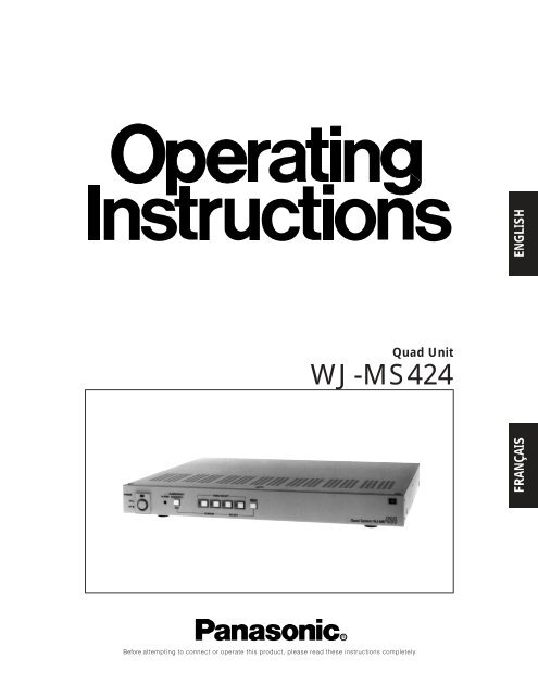
<strong>Quad</strong> Unit<br />
<strong>WJ</strong>-<strong>MS424</strong><br />
FRANÇAIS<br />
ENGLISH<br />
Before attempting to connect or operate this product, please read these instructions completely
CONTENTS<br />
PREFACE .................................................................................................................................................................................. 1<br />
FEATURES ................................................................................................................................................................................ 1<br />
PRECAUTIONS ......................................................................................................................................................................... 1<br />
MAJOR OPERATING CONTROLS AND THEIR FUNCTIONS ................................................................................................... 2<br />
RACK MOUNTING .................................................................................................................................................................... 4<br />
SETTING UP THE MENUS ........................................................................................................................................................ 5<br />
SYSTEM CONNECTIONS ....................................................................................................................................................... 11<br />
SPECIFICATIONS ................................................................................................................................................................... 15<br />
STANDARD ACCESSORIES ................................................................................................................................................... 15<br />
CAUTION<br />
RISK OF ELECTRIC SHOCK<br />
DO NOT OPEN<br />
CAUTION:<br />
Before attempting to connect or operate this product,<br />
please read the label on the bottom.<br />
CAUTION:<br />
TO REDUCE THE RISK OF ELECTRIC SHOCK, DO<br />
NOT REMOVE COVER (OR BACK). NO USER SER-<br />
VICEABLE PARTS INSIDE.<br />
REFER SERVICING TO QUALIFIED SERVICE PER-<br />
SONNEL.<br />
SA 1965<br />
SA 1966<br />
The lightning flash with arrowhead symbol,<br />
within an equilateral triangle, is<br />
intended to alert the <strong>user</strong> to the presence<br />
of uninsulated "dangerous voltage"<br />
within the product's enclosure that may<br />
be of sufficient magnitude to constitute a<br />
risk of electric shock to persons.<br />
The exclamation point within an equilateral<br />
triangle is intended to alert the <strong>user</strong><br />
to the presence of important operating<br />
and maintenance (servicing) instructions<br />
in the literature accompanying the appliance.<br />
For U.S.A<br />
Warning:<br />
This equipment generates and uses radio frequency energy<br />
and if not installed and used properly, i.e., in strict<br />
accordance with the instruction <strong>manual</strong>, may cause harmful<br />
interference to radio communications. It has been tested<br />
and found to comply with the limits for a Class A computing<br />
device pursuant to Subpart J of Part 15 of FCC Rules,<br />
which are designed to provide reasonable protection<br />
against such interference when operated in a commercial<br />
environment.<br />
The serial number of this product may be found on the bottom<br />
of the unit.<br />
You should note the serial number of this unit in the space<br />
provided and retain this book as a permanent record of your<br />
purchase to aid identification in the event of theft.<br />
Model No.<br />
Serial No.<br />
<strong>WJ</strong>-<strong>MS424</strong><br />
WARNING:<br />
TO PREVENT FIRE OR ELECTRIC SHOCK HAZARD, DO NOT EXPOSE THIS APPLIANCE TO RAIN OR MOISTURE.
PREFACE<br />
The <strong>Panasonic</strong> <strong>WJ</strong>-<strong>MS424</strong> <strong>Quad</strong> Unit is ideal for CCTV<br />
applications where multiple surveillance cameras are<br />
required. Most 2 : 1 interlace cameras available today,<br />
either color or black and white, are compatible with the<br />
<strong>WJ</strong>-<strong>MS424</strong>. Up to four cameras may be connected to<br />
the system, and if desired, the monitor can be divided<br />
into 4 windows for simultaneous display of the four different<br />
images.<br />
Simple front panel switch operation allows quick selection<br />
between quad and single camera display modes.<br />
FEATURES<br />
1. Compatible with Most 2 : 1 Interlace cameras<br />
Advanced digital processing technology allows<br />
connection of most 2 : 1 interlace cameras available<br />
today without the requirement for synchronization of<br />
the four video inputs.<br />
The system may be added to existing security systems<br />
and makes possible displays in black and<br />
white or full color.<br />
2. Alphanumeric Character Generator<br />
Title insertion of up to 8 characters in each of the<br />
four windows is possible. This promotes easy identification<br />
of the separate camera locations.<br />
3. Alarm with Built-in Buzzer<br />
This system can be combined with alarm sensors<br />
and switches as well as time-lapse VCRs through<br />
the alarm output and reset signal connectors.<br />
Upon receiving an alarm signal, a full-sized picture<br />
of the site is displayed. By setting the “CAM TITLE<br />
ON” and “ALARM TITLE ON” modes from the TITLE<br />
menu, “ALARM” and the window title will appear<br />
intermittently in the picture.<br />
The Automatic alarm reset time is adjustable from 1<br />
to 30 sec.,1, 2, 3, 4, 5 min. or Off.<br />
4.<strong>Quad</strong> Picture Borderlines<br />
A white borderline can be inserted in the quad pictures<br />
by setting “BORDER ON” from the Setup<br />
Menu.<br />
5. Two kinds of Video Output Connectors<br />
The <strong>Quad</strong> system offers two kinds of video output<br />
connectors :<br />
(a) VIDEO OUT : <strong>Quad</strong> or full-size single picture<br />
can be selected with the front panel switches.<br />
(b) VCR OUT : A quad display is always supplied,<br />
regardless of the setting of the front panel<br />
switches.<br />
6. A back-up memory inside maintains preset title<br />
character information.<br />
7. Video Loss Checking Function<br />
If the video signal is lost due to a disconnected<br />
cable or other reasons, an alarm buzzer beeps and<br />
a caution message is displayed on the monitor<br />
screen.<br />
ENGLISH<br />
PRECAUTIONS<br />
• Do not attempt to disassemble the unit. In order to<br />
prevent electrical shock, do not remove screws or<br />
covers. There are no <strong>user</strong>-serviceable parts inside.<br />
• Do not abuse the unit. Avoid striking, shaking etc. It<br />
could be damaged by improper handling or storage.<br />
• Do not use strong or abrasive detergents when<br />
cleaning the unit body.<br />
• Do not expose the unit to water or moisture, and do<br />
not operate it in wet or humid areas.<br />
• Do not use the unit in an extreme environment<br />
where high temperature or high humidity exists.<br />
• Handle the unit with care.<br />
• Take immediate action if ever the unit does become<br />
wet. Tune the power off and refer servicing to qualified<br />
service personnel. Moisture can damage the<br />
unit and also create a danger of electric shock.<br />
• Use the unit under conditions where temperature is<br />
within –10°C to +50°C (14°F to 122°F), and humidity<br />
is below 90%. When installing the unit in the rack, it<br />
is recommended to install the fan.<br />
• The input power source is 120 V AC, 60 Hz.<br />
• Refer all installation work to qualified service personnel<br />
or system installers.<br />
-1-
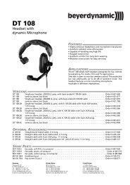
MAJOR OPERATING CONTROLS AND THEIR FUNCTIONS<br />
POWER<br />
ALARM<br />
ALARM RESET<br />
QUAD/SEQ<br />
VIDEO SELECT<br />
MENU<br />
ON<br />
OFF<br />
POWER<br />
PROTECTION<br />
ESC<br />
1 2 3 4<br />
CURSOR<br />
– +<br />
SELECT<br />
<strong>Quad</strong> System <strong>WJ</strong>-MS<br />
OUT<br />
4<br />
IN<br />
OUT<br />
3<br />
VIDEO<br />
IN OUT<br />
2<br />
IN<br />
OUT<br />
1<br />
IN<br />
VCR<br />
OUT<br />
VIDEO<br />
OUT<br />
ALARM/REMOTE<br />
SIGNAL GND<br />
1. Power ON/OFF Switch (POWER)<br />
This switch turns the power of this switch on or off.<br />
The POWER indicator lights when the power of this<br />
unit is on.<br />
Switch Protector (Standard Accessory)<br />
To prevent that the power of this unit is turned off accidentally,<br />
install the supplied switch protector as shown<br />
below.<br />
SWITCH<br />
PROTECTOR<br />
2. Alarm LED (ALARM)<br />
This LED flashes while the alarm signal is received.<br />
It changes to steady light when the alarm is reset<br />
automatically.<br />
To turn the flashing LED off, press the ALARM<br />
RESET/QUAD/SEQ button.<br />
3. Alarm Reset/<strong>Quad</strong>/Sequence/Escape Button<br />
(ALARM RESET/QUAD/SEQ/ESC)<br />
This button has different functions in different<br />
modes, as described below.<br />
• ALARM RESET button<br />
When an alarm signal is received, this button works<br />
as the ALARM RESET button.<br />
Pressing this button in an alarm situation cancels<br />
the alarm mode with the following results:<br />
1. The alarm LED stops flashing.<br />
2. The alarm output is stopped.<br />
3. The alarm buzzer stops beeping.<br />
4. The video loss caution message on the monitor<br />
screen disappears and the screen returns to<br />
the camera picture.<br />
-2-<br />
• QUAD button<br />
When QUAD is selected for VIDEO OUT on the<br />
SYSTEM SETUP menu, this button works as the<br />
QUAD button.<br />
Pressing this button displays the quad picture on<br />
the monitor screen.<br />
• SEQ button<br />
When SEQ is selected for VIDEO OUT on the SYS-<br />
TEM SETUP menu, this button works as the SEQ<br />
button.<br />
Pressing this button displays the pictures on the<br />
monitor screen in the sequential order and with the<br />
dwell time set on the SEQ SETUP menu.<br />
• ESC button<br />
When the setup menu (SYSTEM SETUP, SEQ<br />
SETUP, TITLE SETUP, TITLE SET, or TITLE POSI) is<br />
displayed on the monitor screen, this button works<br />
as the ESC button.<br />
Pressing this button returns the current setup menu to<br />
the previous setup menu.<br />
4. VIDEO SELECT (1, 2, 3, 4)/CURSOR<br />
(4, 5)/SELECT (–, +) Buttons<br />
These buttons select the video signal or move the<br />
cursor on the setup menus.<br />
• VIDEO SELECT(1, 2, 3, 4) buttons<br />
When the setup menu is not displayed, these button<br />
work as VIDEO SELECT button.<br />
Pressing one of these buttons selects a channel to<br />
be displayed in single picture mode.<br />
• CURSOR (4, 5)/SELECT(–, +) buttons<br />
When the setup menu is displayed, these buttons<br />
work as CURSOR (4, 5)/SELECT (–, +) buttons.<br />
Pressing these buttons moves the cursor or select s<br />
a mode or a parameter.
4 button: This button moves the cursor to the left or<br />
selects an item on the setup menus.<br />
5 button: This button moves the cursor to the right<br />
or selects an item on the setup menus.<br />
– button: This button selects a character or a parameter<br />
on the setup menus.<br />
+ button: This button selects a character or a parameter<br />
on the setup menus.<br />
5. Menu Button (MENU)<br />
Pressing this button for approx. 2 seconds displays<br />
the setup menus. Pressing it again for approx. 1<br />
second cancels the display of the setup menus.<br />
6. Video input Connector (VIDEO IN 1, 2, 3, 4)<br />
These connectors receive a composite video signal.<br />
They are automatically terminated.<br />
Notes:<br />
• The input signals must meet the EIA B/W<br />
video signal standard, if the video inputs of this<br />
unit are to be synchronized.<br />
• If the input signals have a high jitter content,<br />
as in the case of a VCR playback picture, it<br />
may not be possible to synchronize this unit.<br />
7. Video Output Connectors<br />
(VIDEO OUT 1, 2, 3, 4)<br />
The video input signals connected to the VIDEO IN<br />
connector are looped through to these connectors.<br />
Connectors a coaxial cable to these connectors<br />
cancels the termination.<br />
8. VCR Output Connector (VCR OUT)<br />
The video signal for the quad picture mode is<br />
always provided at this connector. By connecting it<br />
to the VIDEO IN connector of the time lapse VCR,<br />
you can record the quad picture.<br />
9. Video Output Connector (VIDEO OUT)<br />
The video signal selected by the QUAD/SEQ button<br />
(quad picture) or the VIDEO SELECT button (single<br />
picture) is output from this connector.<br />
10. Alarm/Remote Control Connector<br />
(ALARM/REMOTE)<br />
This connector accepts the alarm signal from associated<br />
alarm sensor units and the remote control<br />
signal from the external equipment.<br />
ALARM RECOVER IN<br />
ALARM RESET OUT<br />
QUAD/SEQ<br />
Menu<br />
Selector<br />
Not Used<br />
ALARM OUT<br />
Not Used<br />
Not Used<br />
REMOTE/ALARM 4<br />
REMOTE/ALARM 3<br />
REMOTE/ALARM 2<br />
REMOTE/ALARM 1<br />
13<br />
12<br />
11<br />
10<br />
9<br />
8<br />
7<br />
6<br />
5<br />
4<br />
3<br />
2<br />
1<br />
25<br />
24<br />
23<br />
22<br />
21<br />
20<br />
19<br />
18<br />
17<br />
16<br />
15<br />
14<br />
GND<br />
Pin-14 to 25 are connected to Ground<br />
Notes:<br />
• The pins #6 Menu and #7 QUAD/SEQ are operable<br />
only when pin #5 Selector is grounded.<br />
• See Specifications for allowable electric capacity<br />
of each pin.<br />
11. Power Cord<br />
-3-
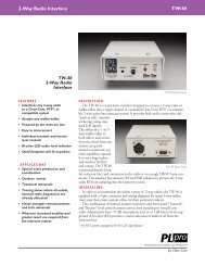
RACK MOUNTING<br />
To install the <strong>WJ</strong>-<strong>MS424</strong> <strong>Quad</strong> Unit in an EIA 19-inch<br />
rack, use the rack mounting brackets (provided) and<br />
eight screws (provided, M3x10).<br />
1. Turn off the power of the unit.<br />
2. Remove the four screws fixing the rubber legs, and<br />
remove the four rubber legs from the unit.<br />
4. Install the unit in the rack with four screws (to be<br />
procured locally).<br />
EIA 19”<br />
rack<br />
Remove four rubber legs.<br />
Cautions:<br />
1. Leave one space free both above and below the<br />
unit, or install a cooling fan in the rack.<br />
2. If the rack is subject to vibrations, secure the rear of<br />
the unit to the rack using additional rack mounting<br />
brackets (to be procured locally).<br />
3. Attach the rack mounting brackets on both sides<br />
and fix them with eight screws (provided).<br />
Eight screws (Provided)<br />
Fix the rack mounting brackets<br />
-4-
SETTING UP THE MENUS<br />
Before the Settings<br />
1. Confirm that the cameras and peripherals are connected<br />
correctly and firmly.<br />
2. Turn on the power of this unit and connected<br />
peripherals.<br />
1. Displaying the Menus<br />
Press the MENU button for 2 seconds or more.<br />
The MAIN menu appears.<br />
To select the desired parameter of the selected<br />
item, press the SELECT (–, +) buttons.<br />
3 4<br />
– +<br />
Note:<br />
Some items have a setting menu (The “*” mark<br />
indicates that a setting menu exists, for example,<br />
SYSTEM SETUP.), press the SELECT (–, +)<br />
buttons to select ON for its parameter. The setting<br />
menu of the selected item appears.<br />
Precaution:<br />
Entering the setup menu is not possible while<br />
the ALARM LED is flashing. Make sure the<br />
alarm mode is canceled. To cancel the alarm<br />
mode, press the ALARM RESET button.<br />
ALARM<br />
ALARM RESET<br />
QUAD/SEQ<br />
ESC<br />
VIDEO SELECT<br />
1 2 3 4<br />
CURSOR<br />
– +<br />
SELECT<br />
MENU<br />
All Reset Operation<br />
All reset allows you to reset all setup menu items to<br />
the factory settings if you are unsure about the correct<br />
settings.<br />
Proceed as follows:<br />
1. Turn the power of this unit off.<br />
2. Keep holding down the CURSOR button (5),<br />
the SELECT button (+), and the MENU button<br />
simultaneously, and press the POWER button.<br />
The buzzer beeps when all settings are reset to<br />
the factory settings.<br />
** MAIN **<br />
SYSTEM SETUP *<br />
ALARM BUZZER 2SEC<br />
ALARM OUT<br />
2SEC<br />
ALARM AUTO RESET OFF<br />
SEQ SETUP *<br />
TITLE SETUP *<br />
You can setup the following items:<br />
• SYSTEM SETUP<br />
• ALARM BUZZER<br />
• ALARM OUT<br />
• ALARM AUTO RESET<br />
• SEQ SETUP<br />
• TITLE SETUP<br />
See the following pages for details about the functions<br />
and settings.<br />
2. How to Operate the Menus<br />
To select the desired item, press the CURSOR (4,<br />
5) buttons. Each time you press a button, the cursor<br />
moves to the next (5) or previous (4) item.<br />
1 2<br />
-5-
3. Setup Menu Description<br />
ALARM<br />
ALARM RESET<br />
QUAD/SEQ<br />
VIDEO SELECT<br />
MENU<br />
3-1. SYSTEM SETUP<br />
The SYSTEM menu lets you set the following<br />
items:<br />
• BORDER<br />
• VIDEO OUT<br />
• AUTO SKIP<br />
• VIDEO LOSS<br />
ESC<br />
1 2 3 4<br />
CURSOR<br />
– +<br />
SELECT<br />
or<br />
1. Move the cursor to SYSTEM SETUP.<br />
2. Press one of the SELECT buttons (– or +). The SYS-<br />
TEM SETUP menu appears on the monitor screen.<br />
Note: To return to the MAIN menu, press the ESC<br />
button.<br />
** SYSTEM SETUP **<br />
BORDER<br />
VIDEO OUT<br />
AUTO SKIP<br />
VIDEO LOSS<br />
ON<br />
QUAD<br />
OFF<br />
ON<br />
ALARM<br />
ALARM RESET<br />
QUAD/SEQ<br />
ESC<br />
1 2 3 4<br />
CURSOR<br />
VIDEO SELECT<br />
– +<br />
SELECT<br />
MENU<br />
or<br />
** SYSTEM SETUP **<br />
BORDER<br />
VIDEO OUT<br />
AUTO SKIP<br />
VIDEO LOSS<br />
ON<br />
QUAD<br />
OFF<br />
ON<br />
Borderline (white)<br />
e<br />
3-1-1. Border (BORDER)<br />
This parameter lets you set the appearance of the borders<br />
that divide the screen.<br />
1. Move the cursor to BORDER.<br />
2. Select ON or OFF.<br />
ON: The borders appear when QUAD is selected<br />
for VIDEO OUT.<br />
OFF: The borders do not appear.<br />
ALARM<br />
ALARM RESET<br />
QUAD/SEQ<br />
ESC<br />
VIDEO SELECT<br />
1 2 3 4<br />
CURSOR<br />
or<br />
** SYSTEM SETUP **<br />
BORDER<br />
VIDEO OUT<br />
AUTO SKIP<br />
VIDEO LOSS<br />
– +<br />
SELECT<br />
ON<br />
QUAD<br />
OFF<br />
ON<br />
MENU<br />
3-1-2. <strong>Quad</strong>/Sequence (VIDEO OUT)<br />
This parameter lets you select the quad picture or<br />
sequential single picture for display on the monitor<br />
screen.<br />
1. Move the cursor to VIDEO OUT.<br />
2. Select QUAD or SEQ.<br />
QUAD: The quad picture appears on the monitor<br />
that is connected to the VIDEO OUT connector.<br />
SEQ: The single picture appears sequentially in<br />
the order to set on the of SEQUENCE SETUP<br />
submenu of the MAIN menu.<br />
** SYSTEM SETUP **<br />
BORDER<br />
VIDEO OUT<br />
AUTO SKIP<br />
VIDEO LOSS<br />
ON<br />
QUAD<br />
OFF<br />
ON<br />
-6-
3-1-3. Auto Channel Skipping (AUTO SKIP)<br />
Setting<br />
This parameter lets you set automatic skipping of channels<br />
to which no camera is connected.<br />
1. Move the cursor to AUTO SKIP.<br />
2. Select ON or OFF.<br />
ON: Channels to which no camera is connected are<br />
skipped when SEQ is selected.<br />
OFF: No channels are skipped.<br />
** SYSTEM SETUP **<br />
BORDER<br />
VIDEO OUT<br />
AUTO SKIP<br />
VIDEO LOSS<br />
ON<br />
QUAD<br />
OFF<br />
ON<br />
3-1-4. Video Loss Checking<br />
(VIDEO LOSS)<br />
This parameter lets you activate a function that checks<br />
whether the video signal is being supplied to the VIDEO<br />
INPUT connector.<br />
1. Move the cursor to VIDEO LOSS.<br />
2. Select ON or OFF.<br />
OFF: The video loss alarm is ignored.<br />
ON: When video loss alarm is received, the picture<br />
switches to the quad format. The message<br />
“CHXX LOSS” appears on the monitor screen<br />
and the alarm buzzer starts beeping.<br />
** SYSTEM SETUP **<br />
BORDER<br />
VIDEO OUT<br />
AUTO SKIP<br />
VIDEO LOSS<br />
ON<br />
QUAD<br />
OFF<br />
OFF<br />
** SYSTEM SETUP **<br />
BORDER<br />
VIDEO OUT<br />
AUTO SKIP<br />
VIDEO LOSS<br />
1<br />
ON<br />
QUAD<br />
ON<br />
ON<br />
1<br />
3-2. ALARM BUZZER<br />
This parameter lets you adjust the buzzer time between<br />
1 and 30 seconds and 1 and 5 minutes.<br />
1. Move the cursor to ALARM BUZZER.<br />
2. Select the buzzer time.<br />
OFF: The alarm buzzer does not beep when an<br />
alarm signal is received.<br />
1-30 SEC, 1-5 MIN: The buzzer keeps on beeping<br />
for the duration you set.<br />
EXT: The alarm buzzer keeps on beeping until an<br />
operation is performed from an external equipment<br />
such as a time lapse VCR.<br />
** MAIN **<br />
2<br />
d<br />
3<br />
SYSTEM SETUP *<br />
ALARM BUZZER<br />
ALARM OUT<br />
ALARM AUTO RESET<br />
SEQ SETUP *<br />
TITLE SETUP *<br />
2SEC<br />
2SEC<br />
OFF<br />
3<br />
OFF 1SEC 2SEC ...... 30SEC<br />
1MIN ...... 5MIN<br />
EXT<br />
4<br />
4<br />
-7-
3-3. ALARM OUT<br />
This parameter lets you adjust the duration the alarm<br />
signal is output between 1 and 30 seconds and 1 and 5<br />
minutes.<br />
1. Move the cursor to ALARM OUT.<br />
2. Select the duration the alarm signal is output.<br />
1-30 SEC, 1-5 MIN: The alarm signal is output for<br />
the duration you set.<br />
** MAIN **<br />
SYSTEM SETUP *<br />
ALARM BUZZER<br />
ALARM OUT<br />
ALARM AUTO RESET<br />
SEQ SETUP *<br />
TITLE SETUP *<br />
2SEC<br />
2SEC<br />
OFF<br />
** MAIN**<br />
SYSTEM SETUP *<br />
ALARM BUZZER<br />
ALARM OUT<br />
ALARM AUTO RESET<br />
SEQ SETUP *<br />
TITLE SETUP *<br />
2SEC<br />
2SEC<br />
OFF<br />
ALARM<br />
ALARM RESET<br />
QUAD/SEQ<br />
ESC<br />
1 2 3 4<br />
CURSOR<br />
VIDEO SELECT<br />
– +<br />
SELECT<br />
MENU<br />
or<br />
1SEC ...... 30SEC<br />
1MIN ...... 5MIN<br />
** SEQ SETUP **<br />
3-4. ALARM AUTO RESET<br />
This parameter lets you set the time until the unit recovers<br />
after receiving the alarm signal.<br />
1. Move the cursor to ALARM AUTO RESET.<br />
2. Select the recover time.<br />
OFF: The alarm condition is maintained until the<br />
ALARM RESET button on the front panel is<br />
pressed or the alarm recover signal from the<br />
time lapse VCR is supplied to the ALARM/<br />
REMOTE connector.<br />
1-30 SEC, 1-5 MIN: The alarm condition is maintained<br />
for the length of the recover time you set.<br />
1: 1CH 2SEC<br />
2: 2CH 2SEC<br />
3: 3CH 2SEC<br />
4: 4CH 2SEC<br />
5: OFF<br />
6: OFF<br />
7: OFF<br />
8: OFF<br />
3. Press the SELECT buttons (–, +) to select the channel.<br />
The channel changes as below:<br />
<br />
1CH 2CH 3CH 4CH QUAD OFF<br />
** MAIN **<br />
SYSTEM SETUP *<br />
ALARM BUZZER<br />
ALARM OUT<br />
ALARM AUTO RESET<br />
SEQ SETUP *<br />
TITLE SETUP *<br />
2SEC<br />
2SEC<br />
OFF<br />
4. Press the CURSOR buttons (4 or 5) so that “SEC”<br />
starts blinking.<br />
The cursor moves in the SEQ SETUP menu as<br />
shown below:<br />
** SEQUENCE **<br />
OFF 1SEC ...... 30SEC 1MIN ...... 5MIN<br />
1: 1CH 2SEC<br />
2: 2CH 2SEC<br />
3: 3CH 2SEC<br />
4: 4CH 2SEC<br />
5: OFF<br />
6: OFF<br />
7: OFF<br />
8: OFF<br />
3-5. SEQ SETUP<br />
This parameter lets you set the sequential order and<br />
dwell time for camera switching.<br />
1. Move the cursor to SEQ SETUP.<br />
2. Press one of the SELECT buttons (– or +). The<br />
SEQUENCE menu appears on the monitor screen,<br />
and “1 CH” starts blinking.<br />
: Cursor Move<br />
5. Select the dwell time by pressing the SELECT buttons<br />
(–, +). The dwell time changes as below:<br />
<br />
1SEC 2SEC 3SEC • • • • 30SEC<br />
-8-
6. Repeat steps 3 to 5 to determine the sequential order<br />
and dwell time.<br />
7. Press the ESC button to return to the MAIN menu.<br />
** TITLE SETUP **<br />
CAM TITLE<br />
TITLE SET *<br />
TITLE POSI *<br />
ALARM TITLE<br />
ON<br />
ON<br />
3-6. TITLE SETUP<br />
A title consisting of up to 8 alphanumeric characters<br />
can be displayed on the monitor.<br />
1. Move the cursor to TITLE SETUP.<br />
2. Press one of the SELECT buttons (– or +). The<br />
TITLE SETUP menu appears on the monitor screen.<br />
ABCDEFGH<br />
ALARM<br />
ALARM RESET<br />
QUAD/SEQ<br />
ESC<br />
** MAIN **<br />
SYSTEM SETUP *<br />
ALARM BUZZER<br />
ALARM OUT<br />
ALARM AUTO RESET<br />
SEQ SETUP *<br />
TITLE SETUP *<br />
VIDEO SELECT<br />
1 2 3 4<br />
CURSOR<br />
** TITLE SETUP **<br />
CAM TITLE<br />
TITLE SET *<br />
TITLE POSI *<br />
ALARM TITLE<br />
– +<br />
SELECT<br />
ON<br />
ON<br />
2SEC<br />
2SEC<br />
OFF<br />
or<br />
MENU<br />
3-6-2. TITLE SET<br />
This parameter lets you edit a displayed title.<br />
1. Move the cursor to TITLE SET.<br />
2. Press one of the SELECT buttons (– or +). The<br />
EDITTING menu appears on the monitor screen<br />
and “1” starts blinking.<br />
3. Move the cursor to the channel number whose title<br />
is to be edited by pressing the CURSOR buttons (4<br />
or 5).<br />
4. Select a character by pressing the SELECT buttons<br />
(– or +).<br />
5. After selecting the first character, press the CUR-<br />
SOR button(5). Then select the second character.<br />
6. Repeat steps 3 to 5 above to complete the title.<br />
7. Repeat steps 3 to 6 to edit the other channels.<br />
8. Press the ESC button to return to the previous<br />
menu.<br />
** TITLE SETUP **<br />
CAM TITLE<br />
TITLE SET *<br />
TITLE POSI *<br />
ALARM TITLE<br />
TITLE EDIT<br />
ON<br />
ON<br />
ON<br />
You can set the following items:<br />
• CAM TITLE<br />
• TITLE SET<br />
• TITLE POSI<br />
• ALARM TITLE<br />
Note: To return to the MAIN menu, press the ESC<br />
button.<br />
ALARM<br />
ALARM RESET<br />
QUAD/SEQ<br />
ESC<br />
VIDEO SELECT<br />
1 2 3 4<br />
CURSOR<br />
– +<br />
SELECT<br />
MENU<br />
or<br />
3-6-1. CAM TITLE<br />
This parameter lets you decide whether or not to have<br />
the title displayed.<br />
1. Move the cursor to the CAM TITLE parameter.<br />
2. Select ON or OFF.<br />
ON: Title display.<br />
OFF: No title display.<br />
1....... 2.......<br />
ABCDEFGHIJKLM<br />
NOPQRSTUVWXYZ<br />
0123456789<br />
←→=?'"#&()* +,<br />
-./:; E (blank)<br />
-9-<br />
3....... 4.......
To erase a specific character<br />
1. Select a character to be erased.<br />
2. Select “•” (blank mark) to erase the character.<br />
To erase the title of a specific channel<br />
1. Move the cursor to the channel number whose title<br />
is to be erased.<br />
2. Press the SELECT buttons (– and +) simultaneously.<br />
3-6-3. TITLE POSI<br />
This parameter lets you select the position on the monitor<br />
screen where you want the title to be displayed.<br />
1. Move the cursor to TITLE POSI.<br />
2. Press one of the SELECT buttons (– or +). The<br />
TITLE POSITION menu appears with the title of the<br />
channel 1 on the monitor screen.<br />
3. Select the position where the title is to be displayed<br />
by pressing the CURSOR buttons (4 or 5).<br />
4. Press the ESC button to return to the previous<br />
menu.<br />
3-6-4. ALARM TITLE<br />
This parameter lets you decide whether or not to have<br />
the word”ALARM” displayed when the unit receives the<br />
alarm signal.<br />
1. Move the cursor to ALARM TITLE .<br />
2. Select ON or OFF.<br />
ON: “ALARM” is displayed<br />
OFF: “ALARM” is not displayed.<br />
** TITLE SETUP **<br />
CAM TITLE<br />
TITLE SET *<br />
TITLE POSI *<br />
ALARM TITLE<br />
ON<br />
ON<br />
** TITLE SETUP **<br />
CAM TITLE<br />
TITLE SET *<br />
TITLE POSI *<br />
ALARM TITLE<br />
ON<br />
OFF<br />
ALARM<br />
1.......<br />
Note: All channel titles will be displayed in the<br />
same position. You cannot specify a different<br />
position for each title.<br />
-10-
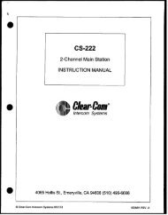
SYSTEM CONNECTIONS<br />
SYSTEM 1<br />
The input video signals for this unit are not synchronized.<br />
VIDEO<br />
VIDEO<br />
VIDEO<br />
VIDEO<br />
<strong>WJ</strong>-<strong>MS424</strong><br />
OUT<br />
4<br />
IN<br />
OUT<br />
3<br />
VIDEO<br />
IN OUT<br />
2<br />
IN<br />
OUT<br />
1<br />
IN<br />
VCR<br />
OUT<br />
VIDEO<br />
OUT<br />
ALARM/REMOTE<br />
SIGNAL GND<br />
Monitor<br />
Monitor<br />
VCR<br />
Notes :<br />
• When pressing the ALARM RESET/QUAD/SEQ/ECS button or the VIDEO SELECT/CURSOR/SELECT buttons, the picture<br />
on the video monitor may roll briefly at the time of switching.<br />
• The video signal to be recorded by the VCR should be supplied from the VCR OUT connector of this unit and not from<br />
the VIDEO OUT/ESC connector of this unit, unless VCR servo control disturbances are allowable when setting the<br />
ALARM RESET/ QUAD/SEQ/ECS button or the VIDEO SELECT/CURSOR/SELECT buttons.<br />
Connections<br />
• Connect the VIDEO IN connectors of this unit to the video output connectors of the cameras.<br />
• Connect the VCR OUT connector of this unit to the video input connector of the time lapse VCR for recording.<br />
• Connect the VIDEO OUT connector of this unit to the video input connector of the video monitor.<br />
-11-
SYSTEM 2<br />
The input video signals for this unit are synchronized, and synchronization noise or disturbances in the video output signal<br />
will not occur when the quad or single picture mode is selected.<br />
GENLOCK GENLOCK GENLOCK GENLOCK<br />
VIDEO<br />
VIDEO<br />
VIDEO<br />
VIDEO<br />
<strong>WJ</strong>-<strong>MS424</strong><br />
OUT<br />
4<br />
IN<br />
OUT<br />
3<br />
VIDEO<br />
IN OUT<br />
2<br />
IN<br />
OUT<br />
1<br />
IN<br />
VCR<br />
OUT<br />
VIDEO<br />
OUT<br />
ALARM/REMOTE<br />
SIGNAL GND<br />
VDA<br />
Monitor<br />
Monitor<br />
VCR<br />
Connections<br />
• Connect the VIDEO IN connectors of this unit to the video output connectors of the cameras.<br />
• Connect the VCR OUT connector of this unit to the video input connector of the video distribution amplifier (V.D.A).<br />
• Connect the output of the video distribution amplifier (V.D.A.) to the video input connector of the time lapse VCR and to<br />
the gen-lock input connectors of the cameras.<br />
• Connect the VIDEO OUT connector of this unit to the video input connector of the monitor.<br />
-12-
SYSTEM 3<br />
A system consisting of this <strong>Quad</strong> Unit and the specified cameras should include the WV-PS104C Camera Drive Unit.<br />
VIDEO<br />
WV-PS104C<br />
CAMERA<br />
IN<br />
4ch<br />
VIDEO<br />
OUT<br />
AUDIO<br />
OUT<br />
CAMERA<br />
IN<br />
3ch<br />
VIDEO<br />
OUT<br />
AUDIO<br />
OUT<br />
CAMERA<br />
IN<br />
2ch<br />
VIDEO<br />
OUT<br />
AUDIO<br />
OUT<br />
CAMERA<br />
IN<br />
1ch<br />
VIDEO<br />
OUT<br />
AUDIO<br />
OUT<br />
VD/SYNC<br />
IN<br />
VD/SYNC<br />
OUT<br />
CAUTION<br />
(4Vp-p 75Ω)<br />
<strong>WJ</strong>-<strong>MS424</strong><br />
OUT<br />
4<br />
IN<br />
OUT<br />
3<br />
VIDEO<br />
IN OUT<br />
2<br />
IN<br />
OUT<br />
1<br />
IN<br />
VCR<br />
OUT<br />
VIDEO<br />
OUT<br />
ALARM/REMOTE<br />
SIGNAL GND<br />
Monitor<br />
Monitor<br />
VCR<br />
Note: When pressing the ALARM RESET/QUAD/SEQ/ESC button or the VIDEO SELECT/CURSOR/SELECT buttons, the picture<br />
on the video monitor may roll briefly at the time of switching.<br />
Connections<br />
• Connect the VIDEO IN connectors of this unit to the video output connectors of the WV-PS104C Camera Drive Unit.<br />
• Connect the VIDEO OUT connector of this unit to the video input connector of the monitor.<br />
• Connect the VCR OUT connector of this unit to the video input connector of the time lapse VCR.<br />
• Connect the video output connectors of the cameras to the camera input connectors of the WV-PS104C Camera Drive<br />
Unit.<br />
-13-
SYSTEM 4<br />
Sensor<br />
Sensor<br />
Sensor<br />
Sensor<br />
<strong>WJ</strong>-<strong>MS424</strong><br />
OUT<br />
4<br />
IN<br />
OUT<br />
3<br />
VIDEO<br />
IN OUT<br />
2<br />
IN<br />
OUT<br />
1<br />
IN<br />
VCR<br />
OUT<br />
VIDEO<br />
OUT<br />
ALARM/REMOTE<br />
SIGNAL GND<br />
Monitor<br />
Monitor<br />
VCR<br />
Connections<br />
• Connect the VIDEO IN connectors of this unit to the video output connectors of the cameras.<br />
• Connect the VCR OUT connector of this unit to the input connector of the time lapse VCR.<br />
• Connect the VIDEO OUT connector of this unit to the input connector of the monitor.<br />
• Connect the wires of the alarm sensors to the alarm input pins of ALARM/REMOTE connector.<br />
• Connect the ALARM OUTPUT pin of the ALARM/REMOTE connector of this unit to the alarm input terminal of the time<br />
lapse VCR.<br />
• Connect the recover output (alarm reset output) of the time lapse VCR to the ALARM RECOVER IN pin of the ALARM<br />
/REMOTE connector of this unit.<br />
• Connect the ALARM RESET OUT pin of the ALARM/REMOTE connector of this unit to the alarm reset in terminal of the<br />
time lapse VCR.<br />
-14-
SPECIFICATIONS<br />
Video Input :<br />
Video Output :<br />
Title :<br />
Alarm Input :<br />
Alarm Output :<br />
Alarm Time :<br />
Recover Input :<br />
Auto Reset Time :<br />
Ambient Operating Temperature :<br />
Power Source and<br />
Power Consumption:<br />
Dimensions :<br />
Weight :<br />
2:1 interlace, composite 1V [p-p] 75 Ω, auto termination or loop-through, black and white or<br />
color video signal x 4 (Each video signal should be synchronized vertically for vertical interval<br />
switching. Does not have to be synchronized in case vertical interval switching is not<br />
required.)<br />
Video Output x 1, composite, 1V [p-p] 75 Ω, color or black and white video signal with composite<br />
sync and burst signal.<br />
Up to 8 characters per window<br />
One per 4 video inputs (max. DC 12V and a make-contact for ground)<br />
One (max. DC 24V, 100mA, open collector circuit)<br />
Adjustable approx. 1s to 30s, 1, 2, 3, 4, 5 min. or EXT<br />
One (max. DC 12V and a make-contact for ground)<br />
Adjustable approx. 1s to 30s, 1, 2, 3, 4, 5 min. or OFF<br />
−10˚C to +50˚C (14˚F to 122˚F)<br />
AC 120V, 60Hz, 13W<br />
420 (W) x 44 (H) x 350 (D) mm<br />
[16-1/2” (W) x 1-3/4” (H) x 13-3/4” (D)]<br />
3.6 kg (7.9 lbs.)<br />
Weight and Dimensions shown above are approximate.<br />
Specifications are subject to change without notice.<br />
STANDARD ACCESSORIES<br />
Rack Mounting Brackets ................................................1 set<br />
Rack Mounting Bracket Fixing Screws ..........................8 pcs<br />
Switch Protector .............................................................1 pc<br />
-15-
Video Imaging Systems Company<br />
A Division of <strong>Panasonic</strong> Broadcast & Television Systems Company<br />
A Unit of Matsushita Electric Corporation of America<br />
Executive Office: One <strong>Panasonic</strong> Way 4H-2, Secaucus, New Jersey 07094<br />
Regional Offices:<br />
Northeast: One <strong>Panasonic</strong> Way, Secaucus, NJ 07094 (201) 348-7303<br />
Southeast: 1225 Northbrook Parkway, Suite 1-160, Suwanee, GA 30024 (770) 338-6838<br />
Midwest: 1707 North Randall Road, Elgin, IL 60123 (847) 468-5211<br />
Southwest: 8105 Beltsline Road, Suite 100, Irving, TX 75063 (927) 915-1334<br />
Western: 6550 Katella Ave., Cypress, CA 90630 (714) 373-7840<br />
PANASONIC CANADA INC.<br />
5770 Ambler Drive, Mississauga, Ontario, L4W 2T3 Canada (905)624-5010<br />
PANASONIC SALES COMPANY<br />
DIVISION OF MATSUSHITA ELECTRIC OF PUERTO RICO, INC.<br />
San Gabriel Industrial Park, 65th Infantry Ave. KM. 9.5 Carolina, P.R. 00630 (809)750-4300<br />
N0398-2052 YWV8QA4907CN Printed in Japan<br />
N 30<br />
Imprimé au Japon