Clear Com CS-222 Two Channel Main Station user manual - Talamas
Clear Com CS-222 Two Channel Main Station user manual - Talamas
Clear Com CS-222 Two Channel Main Station user manual - Talamas

Create successful ePaper yourself
Turn your PDF publications into a flip-book with our unique Google optimized e-Paper software.
<strong>CS</strong>-<strong>222</strong><br />
2-<strong>Channel</strong> <strong>Main</strong> <strong>Station</strong><br />
INSTRUCTION MANUAL<br />
<strong>Clear</strong>-m r e<br />
*il I<br />
OF intercom Systems<br />
0 4065 Hollis St., Emeryville, CA 94608 (510) 496-6666<br />
© <strong>Clear</strong>-Corn Intercom Systems 810133 9/25/91 REV. A
<strong>Clear</strong>-<strong>Com</strong> <strong>CS</strong>-<strong>222</strong> 2-<strong>Channel</strong> <strong>Main</strong> <strong>Station</strong><br />
O CLEAR-COM LIMITED WARRANTY<br />
<strong>Clear</strong>-<strong>Com</strong> products are warranted to be free from defects in materials<br />
and workmanship for a period of one year from the date of sale.<br />
<strong>Clear</strong>-<strong>Com</strong>'s sole obligation during the warranty period is to provide,<br />
without charge, the parts and labor necessary to remedy covered defects<br />
appearing in products returned prepaid to <strong>Clear</strong>-<strong>Com</strong>, 945 Camelia St.,<br />
Berkeley, Ca. 94710-1484, U.S.A.<br />
This warranty does not cover any defect, malfunction or failure caused<br />
beyond the control of <strong>Clear</strong>-<strong>Com</strong>, including unreasonable or negligent<br />
operation, abuse, accident, failure to follow instructions in the Manual,<br />
defective or improper associated equipment, attempts at modification<br />
and repair not authorized by <strong>Clear</strong>-<strong>Com</strong>, and shipping damage. Products<br />
with their serial numbers removed or defaced are not covered by this<br />
warranty.<br />
To obtain warranty service, follow the procedures described below in<br />
"Procedures for Returns" and "Shipping to Manufacturer for Repair or<br />
Adjustment."<br />
This warranty is the sole and exclusive express warranty given with<br />
respect to <strong>Clear</strong>-<strong>Com</strong> products. It is the responsibility of the <strong>user</strong> to<br />
determine before purchase that this product is suitable for the <strong>user</strong>'s<br />
intended purpose.<br />
Any and all implied warranties, including the implied warranty of merchantability<br />
are limited to the duration of this express limited warranty.<br />
Neither <strong>Clear</strong>-<strong>Com</strong> nor the dealer who sells <strong>Clear</strong>-<strong>Com</strong> products is liable<br />
for incidental or consequential damages of any kind.<br />
Return Shipping Instructions<br />
Procedures for returns:<br />
--If repair is necessary, contact the dealer where the unit was purchased.<br />
--If repair through the dealer is not possible, contact the <strong>Clear</strong>-<strong>Com</strong><br />
Customer Service Department, located at the factory, as directed<br />
below. They will issue a Return Authorization Number (RMA).<br />
--Do not return any equipment to the factory without first obtaining a<br />
Return Authorization Number.<br />
--Be prepared to provide your company's name, address, phone number,<br />
name of person to contact regarding the repair, type and quantity of the<br />
equipment, description of the defect, and the equipment serial<br />
number(s).<br />
Questions regarding returns for repair should be directed to:<br />
Customer Service Department<br />
<strong>Clear</strong>-<strong>Com</strong> Intercom Systems<br />
4065 Hollis Street<br />
Emeryville, California 94608-3505<br />
Telephone: (510) 496-666<br />
Fax: (510) 496-6699<br />
11/90 Rev. 1.0 Page 2
<strong>Clear</strong>-<strong>Com</strong> <strong>CS</strong>-<strong>222</strong> 2-<strong>Channel</strong> <strong>Main</strong> <strong>Station</strong><br />
Shipping IQ Manufacturer f<br />
Repair lr j l<br />
aimmnt<br />
All shipments of <strong>Clear</strong>-<strong>Com</strong> equipment must be prepaid via United<br />
Parcel Service or the best available shipper. The equipment should be<br />
shipped in the original packing container; however, it the original container<br />
is not available, use a suitable container that is rigid and of adequate<br />
size: if a substitute container is used, the equipment should be<br />
wrapped in paper and surrounded with at least four inches of excelsior or<br />
similar shock-absorbing material. A detailed description of the problem<br />
or work to be done should be included. All shipments should be directed<br />
to the attention of the Customer Service Department and must include<br />
the Return Authorization Number.<br />
Upon completion of repairs, equipment will be returned collect via United<br />
Parcel Service or other specified shipper.<br />
NOTICE ABOUT SPECIFICATIONS<br />
Performance specifications included in this <strong>manual</strong> are design-center<br />
specifications and are included for customer guidance and to facilitate<br />
system installation. Actual operating performance may vary.<br />
BEFORE YOU BEGIN ...<br />
To get the most out of the <strong>CS</strong>-<strong>222</strong> <strong>Main</strong> <strong>Station</strong>, read this <strong>manual</strong><br />
carefully. It will answer questions you might have about the operation<br />
and service of the components in the system. Included is a Troubleshooting<br />
Section that provides causes and possible solutions to problems you<br />
might have with system and component operation. <strong>Clear</strong>-<strong>Com</strong>'s Customer<br />
Service Department is available to answer questions not covered<br />
in this <strong>manual</strong>.<br />
It is assumed you are familiar with the operation of basic intercom<br />
systems. If you are not, it is important to read the section titled "The<br />
<strong>Clear</strong>-<strong>Com</strong> Concept".<br />
11/90 Rev. 1.0 Page 3
DESCRIPTION / <strong>Clear</strong>-Corn <strong>CS</strong>-<strong>222</strong> 2-<strong>Channel</strong> <strong>Main</strong> <strong>Station</strong><br />
O SECTION 1<br />
DESCRIPTION OF THE <strong>CS</strong>-<strong>222</strong> 2-CHANNEL INTERCOM STATION<br />
CLEAR-COM CONCEPT<br />
<strong>Clear</strong>-<strong>Com</strong> is a closed-circuit intercom system that consistently provides high-clarity<br />
communication in high-noise and low-noise environments. A basic system consists of a<br />
single- or multi-channel power supply or main station connected to various single- or<br />
multi-channel remote stations, such as beltpacks and loudspeaker stations.<br />
<strong>Clear</strong>-<strong>Com</strong> manufactures a wide variety of both portable and fixed-installation units. All<br />
are compatible with each other. <strong>Clear</strong>-<strong>Com</strong> intercom systems can also interface with<br />
other communication systems and devices.<br />
<strong>Clear</strong>-<strong>Com</strong> stations are interconnected with two-conductor, shielded microphone cable,<br />
using 3-pin XLR connectors. One wire carries the DC power (28-30 volts) from a main<br />
station or power supply to all remote stations, and the other wire carries 2-way (duplex)<br />
audio information. The shield acts as a common ground. One termination (per channel)<br />
Is needed throughout the intercom network, and is usually located in the main station or<br />
power supply.<br />
<strong>Clear</strong>-<strong>Com</strong> is a distributed amplifier system; each main and remote station houses its<br />
own mic preamplifier, headset or speaker power amplifier, and signaling circuitry. The<br />
Automatic Headset Detection circuit shuts off a station's mic pre-amp when the headset<br />
is disconnected, so background noise on the line is not increased by an unused yet online<br />
station. Low-impedance mic input lines (200 Ohms) and specially designed circuitry<br />
make <strong>Clear</strong>-<strong>Com</strong> channels virtually immune to RFI and dimmer noise.<br />
<strong>Clear</strong>-<strong>Com</strong> main stations, power supplies and certain remote stations each have an<br />
auxiliary program input with its own volume control, which allows an external audio<br />
source to be fed to the intercom system.<br />
Visual Signal Circuitry (CALL Lights), a standard feature on most main and remote<br />
stations, allows the <strong>user</strong> to attract the attention of operators who have removed their<br />
headsets.<br />
Depending upon the type of main and remote stations selected and assuming that<br />
enough DC power is available, a maximum number of remote stations from 10 (all<br />
speaker stations) to 30 (all headset stations) can be distributed along a mile of wire.<br />
Remote stations bridge the intercom line at a very high impedance (>10 KOhms), and<br />
place a minimum load on the line. The audio level always remains constant, and does<br />
not fluctuate as stations leave and join the network.<br />
0<br />
The 28-30 volts DC provided by main stations and power supply units enable remote<br />
stations to operate with minimal current (25 mA. quiescent for headset stations, 50 mA.<br />
quiescent for speaker stations) while generating extremely loud listen volumes (greater<br />
than 110dB SPL using <strong>Clear</strong>-<strong>Com</strong> Headsets). The highervoltageand lowcurrent keep<br />
voltage losses to an absolute minimum in long lines. If the supply voltage drops due to<br />
the addition of great length of cable or many more stations, <strong>Clear</strong>-<strong>Com</strong> equipment will<br />
continue operating with less than 12 volts available.<br />
2/92 Rev. 1.1 Page 4
DESCRIPTION / <strong>Clear</strong>-<strong>Com</strong> <strong>CS</strong>-<strong>222</strong> 2-<strong>Channel</strong> <strong>Main</strong> <strong>Station</strong><br />
1.1 <strong>CS</strong>-<strong>222</strong> OVERALL DESCRIPTION<br />
The <strong>CS</strong>-<strong>222</strong> is a portable, two-channel main station with a regulated power supply and a<br />
versatile monitoring system. It features excellent speech intelligibility in all noise-levels.<br />
The <strong>CS</strong>-<strong>222</strong> contains a mic preamp with a limiter. The <strong>CS</strong>-<strong>222</strong>'s four-watt power amp<br />
can drive a standard <strong>Clear</strong>-<strong>Com</strong> headset to levels greater than 110 dB SPL.<br />
The <strong>CS</strong>-<strong>222</strong> provides DC voltage and the ability to talk & listen on two separate<br />
channels. It supports and monitors two intercom lines containing as many as 30 remote<br />
head-set or 6 remote speaker stations.<br />
CLEAR-COM<br />
N~~~ i. ' lPw ato.<br />
~2*0 .00 0<br />
__<br />
113 Ran ax ulm _ amo ~_<br />
WO%± a m<br />
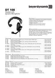
<strong>CS</strong>-<strong>222</strong> Front Panel<br />
<strong>CS</strong> <strong>222</strong> Rear Panel<br />
_ se on jf~~~lm r -_ 5<br />
N~~~hWo<br />
A<br />
PAd L.<br />
L~~~~~~~~~~~I<br />
Ad M<br />
_M<br />
<strong>CS</strong>-<strong>222</strong> Block Diagram<br />
11/90 Rev. 1.0 Page 5
DESCRIPTION / <strong>Clear</strong>-Corn <strong>CS</strong>-<strong>222</strong> 2-<strong>Channel</strong> <strong>Main</strong> <strong>Station</strong><br />
Monitoring System<br />
The front panel of the <strong>CS</strong>-<strong>222</strong> has one headset connector for use by the operator.<br />
The operator monitors the intercom channels turning up the appropriate "Listen Level"<br />
volume controls (one for <strong>Channel</strong> A, one for <strong>Channel</strong> B). Either channel may be<br />
monitored separately, or both simultaneously (without tying the two channels<br />
together). These volume controls are always active regardless of "Talk" channel<br />
selection on the station.<br />
The jack marked "Earphone" is connected in parallel with the earphone circuit of the<br />
headset connector. It can be used for monitoring or recording.<br />
DualkActUon DX Buttons<br />
Each channel has its own "Talk" button which can either "Latch" on, or operate<br />
momentarily.<br />
Pressing the button quickly will "toggle" the "talk" function, alternately turning it on or<br />
off.<br />
The "Talk" button will illuminate dimly when activated.<br />
Stage Announce (Paging)<br />
The "STAGE ANNOUNCE" button on the front panel sends the signal from the<br />
operator's headset microphone preamp to the balanced, line-level Stage Announce<br />
output on the back panel.<br />
The Stage Announce button also mutes the operator's voice output to the intercom<br />
channels. This mute function can be defeated with an internal <strong>user</strong> selectable jumper.<br />
The "STAGE ANNOUNCE" button also activates a SPDT from "C" relay when<br />
pressed. The 1 amp contacts can be used for any <strong>user</strong> desired control function (i.e.<br />
muting a local monitor speaker).<br />
Call Sianaling<br />
Visual "Call- Signaling attracts the attention of people who have removed their<br />
headsets or turned off their speakers. The <strong>CS</strong>-<strong>222</strong> front panel provides a "Call"<br />
button for each channel. Pressing the desired channel button turns on the "Call"<br />
lights at all stations on that channel. The "Call" is active regardless of talk status.<br />
When a remote station sends a Call signal, the lamp in the 'Talk" button associated<br />
with that station's channel lights brightly, whether or not the channel is selected.<br />
Program Input<br />
The <strong>CS</strong>-<strong>222</strong> accepts a balanced, mic-level or line-level program input which can be<br />
monitored in the headset. Program volume for the operators headset is adjustable<br />
with the "Program Monitor knob on the front panel.<br />
The external program is also assignable and adjustable in level to either or both<br />
channels, and mixes with the Intercom signal. The program feed can be set to be<br />
interrupted by the "TALK" for a particular channel.<br />
Skietone<br />
The "Sidetone Adjust" controls for each channel on the front panel allows adjustment<br />
0 of the operators own voice as heard in the headset.<br />
11/90 Rev. 1.0 Page 6
DESCRIPTION / <strong>Clear</strong>-Corn <strong>CS</strong>-<strong>222</strong> 2-<strong>Channel</strong> <strong>Main</strong> <strong>Station</strong><br />
LINKino <strong>Channel</strong>s Taethe<br />
A front panel switch is provided that allows the operator to instantly connect channel A<br />
and channel B together for a combined intercom system consisting of both channels.<br />
Reonte Mk-Kill Function<br />
The <strong>CS</strong>-<strong>222</strong> provides the ability to turn off any open-mics on Series 500 belt-pack<br />
remote stations. Momentarily pressing the <strong>Channel</strong> A RMK button will remove the<br />
DC power from both channels clearing the 'talk' function of all the belt-packs.<br />
Power Sunnlv Protetion<br />
The <strong>CS</strong>-<strong>222</strong> power supply Is regulated, current-limited, and provides 30 volts DC at<br />
I A from a 11 5V or 230V (selectable) AC mains supply. The <strong>CS</strong>-<strong>222</strong> has an<br />
automatic short-circuit sensor to protect the system from miswired cable or shorts in<br />
the lines or general current overload. If a short occurs, the red LED on the front panel<br />
marked "Short" illuminates. Removing the short, will cause the power-supply to reset<br />
itself automatically within 5 seconds<br />
Sysem TEerminaio<br />
The <strong>CS</strong>-<strong>222</strong> provides individually selectable audio termination networks for both<br />
channels A and B.<br />
Portabilit<br />
The unit is light-weight, weather-resistant, and assembled with a sturdy plastic<br />
carrying strap and four protective rubber feet.<br />
Easy Interconnection<br />
The <strong>CS</strong>-<strong>222</strong> provides three 3-pin, male XLR outputs for <strong>Channel</strong> A (connectors are<br />
wired in paralleD and three for <strong>Channel</strong> B. Intercom signals are fed from the <strong>CS</strong>-<strong>222</strong><br />
with standard mic cable (see next section).<br />
E<br />
xSystem Expanon<br />
The <strong>CS</strong>-<strong>222</strong> can be ganged together with other <strong>CS</strong>-<strong>222</strong>'s or other <strong>Clear</strong>-Coin powersupplies<br />
for multiple two-channel systems and back-up power support.<br />
The <strong>CS</strong>-<strong>222</strong> is available with a rack-mount kit for adapting it to standard 19"<br />
equipment racks. The <strong>Clear</strong>-<strong>Com</strong> part number for the <strong>CS</strong>-<strong>222</strong> Rack-Mount Kit is<br />
RK-101.<br />
05192 Rev. 1.1 Page 7
DESCRIPTION / <strong>Clear</strong>-<strong>Com</strong> <strong>CS</strong>-<strong>222</strong> 2-<strong>Channel</strong> <strong>Main</strong> <strong>Station</strong><br />
O<br />
1.2 TECHNICAL SPECIFICATIONS:<br />
MICROPHONE PRE-AMP:<br />
--Dynamic Headset Input: ------------------------ Input Impedance - 1 KOhms<br />
Input Level - -55 dBv* nominal<br />
Input Level - -10 dBv* max.<br />
--Frequency Response: --------------------------- 250 Hz to 12 KHz, contoured for intelligibility.<br />
--Limiter Range: ---------------------------- 20 dB<br />
--Gain from Headset to intercom Line: --------- +41 dB<br />
HEADPHONE AMPLIFIER:<br />
--Load Impedance: --------------------------------- 50-2000 Ohms<br />
--Output Level: --------------------------------------- at least +20 dBv* across 600 ohm<br />
--Distortion: -----------------------------------------
INSTALLATION I <strong>Clear</strong>-CoM <strong>CS</strong>-<strong>222</strong> 2-<strong>Channel</strong> <strong>Main</strong> <strong>Station</strong><br />
SECTION 2<br />
INSTALLATION OF THE <strong>CS</strong>-<strong>222</strong> 2-CHANNEL MAIN STATION<br />
2.1 INSTALLATION OVERVIEW<br />
The <strong>CS</strong>-<strong>222</strong> is a combination of a very versatile intercom station and a system power<br />
supply. Installations can vary depending on what features are used.<br />
The fundamental concept of <strong>Clear</strong>-<strong>Com</strong> Party-Line intercom is that all stations<br />
provide high impedance current sourced signals into a single common system<br />
termination. The line drivers in a station have a source impedance greater than 10<br />
KOhms.<br />
The termination of an intercom line (or channel) is a 220 Ohm resistor in series with a<br />
4.7 KOhm that is paralleled with a 10 uF capacitor. The impedance of the network at<br />
audio frequencies is 220 Ohms. The DC resistance of the network is 5 KOhms. The<br />
high DC resistance allows a CALL voltage to be placed on the line without drawing<br />
too much current. A CALL signal is a DC voltage greater than 10 volts on the line.<br />
The DC source for this CALL signal is also a current source there by providing a high<br />
impedance and not affecting the audio signal.<br />
The receive or "listen" section of stations contain a 'hybrid null' circuit that attempts to<br />
reject (null) any "talk" signal being sent by that station on that channel. The 'hybrid<br />
null' circuit depends on a known impedance on the intercom line to accomplish this.<br />
Variations in impedance on the line upset the 'null'.<br />
<strong>Clear</strong>-Corn main and some remote stations provide switch selectable termination<br />
networks on all intercom output lines. It is up to the <strong>user</strong> to determine where the<br />
termination will be provided. An unterminated line will cause excessive levels,<br />
possible oscillation of line drivers, and sever unbalance of hybrid null networks. A<br />
double or multiple terminated line will cause low levels and sever unbalance of hybrid<br />
null circuits.<br />
CAUTION: All <strong>Clear</strong>-Corn Intercom lines must be terminated. Care must be taken<br />
not to fall to terminate or to 'double' terminate a line. All unused intercom inputs<br />
must be terminated to keep the line drive circuits stable.<br />
CLEAR-COM STATION TYPES:<br />
<strong>Clear</strong>-Corn party-line intercom stations all fall into one of four distinct categories that<br />
relate to system powering and termination. The four types are as follows:<br />
A. MAIN STATION:------ Supplies system power for external stations.<br />
Provides switch selectable terminations.<br />
B. MASTER STATION: - Contains a power supply just for itself.<br />
- Provides switch selectable line terminations.<br />
C. REMOTE STATION: - No power supply. Derives power from the Intercom line.<br />
- May or may not have terminations.<br />
D. POWER SUPPLY: --- Supplies system power for external stations.<br />
--- Provides switch selectable terminations.<br />
11/90 Rev. 1.0 Page 9
INSTALLATION I Clhar-Corn <strong>CS</strong>-<strong>222</strong> 2-<strong>Channel</strong> <strong>Main</strong> <strong>Station</strong><br />
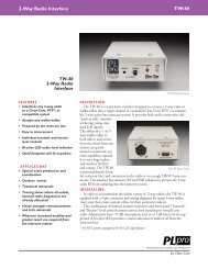
SYSTEM POWERING: Typical <strong>Clear</strong>-<strong>Com</strong> systems consist a a MAIN STATION and<br />
multiple REMOTE STATIONS. The REMOTE STATIONS are powered from the MAIN<br />
STATION through the Intercom cable.<br />
RS-501 CC-75B RS-501 CC-75B RS-SO1 CC-75B RS-5O1 CC-758<br />
TERMINATONS ON<br />
TO OTHER<br />
LEL . ACKS<br />
<strong>222</strong>/~~~~~~~~~~~~~B 111A11'<br />
Typical Single Power Source System<br />
<strong>Clear</strong>-<strong>Com</strong> power supplies can be paralleled to Increase the number of REMOTE<br />
STATIONS that can be operated in a system. The <strong>CS</strong>-<strong>222</strong>, MS-<strong>222</strong>, and the PS-22 will<br />
provide I A of current.<br />
By simply connecting a PS-22 or another <strong>CS</strong>-<strong>222</strong> in parallel with an existing <strong>CS</strong>-<strong>222</strong> the<br />
current capacity of the system Is raised to 2 A. The termination switches in the second<br />
power source would need to be in the OFF position. NOTE: h fKfunction sllno<br />
woNk on 1 system IBM haa tw r more ower sunnliesn<br />
RS-501 CC-75B RS-501 CC-75B RS-5O1 CC-756 RS-501 CC-75B<br />
TERMINATIONS ON<br />
BELTPACKS<br />
RS-5O1 CC-7SB RS-501 CC-75B<br />
OR<br />
PS-22<br />
TERMINATIONS OFF<br />
System With Multiple Power Sources<br />
TO OTHER<br />
BELTPACKS<br />
OR PRODUCTS<br />
05/92 Rev. 1.1 Page 10
INSTALLATION / <strong>Clear</strong>-<strong>Com</strong> <strong>CS</strong>-<strong>222</strong> 2-<strong>Channel</strong> <strong>Main</strong> <strong>Station</strong><br />
2.2 CABLE CONSIDERATIONS:<br />
The <strong>Clear</strong>-<strong>Com</strong> intercom line is intended to run on a shielded twisted pair of cable per<br />
channel of intercom. One conductor carries full duplex ("two-way") audio, the other<br />
conductor carries the DC power for remote stations. The shield is used for ground<br />
return for audio and power. When choosing interconnect cable, keep the following<br />
considerations in mind:<br />
1. DC resistance of the ground or common conductor affects crosstalk. For runs<br />
longer than 100 feet do not use wire smaller than 20 gauge. The total<br />
resistance of the ground return (the combined parallel sum of all shields to a<br />
location) to any point in the system should be under 1.5 ohms.<br />
2. The capacitance of the interconnect cable affects system frequency response and<br />
side-tone stability. Total capacitance should not be greater than 0.25 uF<br />
(capacitance between conductor and shield) equivalent to an intercom system<br />
containing 5000 feet of cable at 50 pF per foot.<br />
PORTABLE INSTALLATION CABLE<br />
Typical cable for portable system interconnections is flexible, two-conductor, shielded<br />
microphone cable. For runs less than 500 feet a cable made of 24 gauge wire is<br />
acceptable. For runs longer than 500 feet use a 20 gauge cable or larger.<br />
Portable remote stations such as beft-packs have a pair of input and output<br />
connectors; when installing a system that includes these, they can be "daisy-chained"<br />
or "loop-thru" connected along one interconnect path. <strong>Clear</strong>-<strong>Com</strong> provides a one<br />
input by three output Line-Splitter (OP-100) that can also simplify wiring. Daisy-<br />
Chaining and Line-Splitting decreases the amount of cable required and simplifies the<br />
installation.<br />
PERMANENT INSTALLATION CABLE<br />
Vinyl-jacketed shielded pair is the cable of choice for permanent installations. Use a<br />
low-capacitance 20 gauge wire for short runs (under 500 feet) and 18 gauge cable for<br />
runs greater than 500 feet. Placing the cable in conduit is recommended but not<br />
necessary.<br />
Multi-pair cable that is individually shielded is acceptable for use in multi-channel<br />
systems. For cross-talk considerations the shields must be tied together on both ends<br />
of the cable to produce the lowest possible DC path for ground return.<br />
11/90 Rev. 1.0 Page 11
INSTALLATION / <strong>Clear</strong>-<strong>Com</strong> <strong>CS</strong>-<strong>222</strong> 2-<strong>Channel</strong> <strong>Main</strong> <strong>Station</strong><br />
* 2.3 REAR PANEL DESCRIPTION<br />
CIL<br />
SS<br />
<strong>CS</strong>-<strong>222</strong> Rear Panel<br />
1. Power Swltch<br />
The AC "Power Switch" is located on the top left corner of the rear panel. The switch<br />
is a rocker switch with a "1"n mark for on and "0" for off.<br />
i<br />
2. Power Connector<br />
Just below the power switch is an EIA power receptacle for either 115 or 230 VAC<br />
~~~power input.<br />
w ~~3. Power Voltage Select and Fuse Block<br />
Just below the EIA receptacle is a plug-in fuse block. By placing a flat blade<br />
screwdriver in the slot between the connector and the block and twisting slightly the<br />
fuse block will release from the connector.<br />
<strong>Com</strong>plete removal of the block will give access to both fuses. Both fuses are identical<br />
in value regardless of the AC voltage applied.<br />
By turning the block over when replacing it in the receptacle will convert the input<br />
voltage range. lii yvllgta range that ini sad rigflt aid e u n Ibottomni of a bflc<br />
in Ibnt winf selected<br />
4. Intercom Line Connectors<br />
There are two sets Of three XLR-SM intercom connectors for both channel outputs.<br />
Standard <strong>Clear</strong>-Corn wiring is as follows: Pin 1 -- Ground<br />
Pin 2-- +30 VDC<br />
Pin 3 - intercom Audio<br />
5. Termination Switches<br />
Each intercom channel is provided with a 'Termination" switch allowing easy<br />
termination of the intercom line. The switch is provided in case there are multiple<br />
MAIN stations connected to the inter-corn line.<br />
CAUTION: FOR PROPER OPERATION IT IS IMPERATIVE THAT QMJAND OLY<br />
0 DUE TERMINATION BE PRESENT ON A CLEAR-COM INTERCOM LINE. CLEAR-<br />
COM LINE DRIVERS DEPEND ON A KNOWN LOAD VALUE FOR PROPER<br />
OPERATION.<br />
11/90 Rev. 1.0 Page 12
INSTALLATION / <strong>Clear</strong>-Corn <strong>CS</strong>-<strong>222</strong> 2-<strong>Channel</strong> <strong>Main</strong> <strong>Station</strong><br />
6. Announce Output Connector<br />
The "Announce" output is a XLR-3M. The output is transformer isolated, 600 ohms<br />
output impedance, and has an output level of approximately 0 dBv.<br />
Wiring is as follows: Pin 1 -- Ground<br />
Pin 2 --- Audio<br />
Pin 3 -- +Audio<br />
7. Announce Relay Contact Terminals<br />
The "Announce" relay contacts are available on a screw terminal block. The relay<br />
contacts are "Form C" (break before make). The contact description is as follows:<br />
Left most ---- N/O --- Normally Open Contact<br />
Center ------- C --- Wiper<br />
Right most -- N/C --- Normally Closed Contact<br />
8. Program Input Connector<br />
The "Program" input is a XLR-3F. It is an electronically balanced (differential) input.<br />
Wiring is as follows: Pin 1 -- Ground<br />
Pin 2-- -Audio<br />
Pin 3 - +Audio<br />
9. Program Gain Switch<br />
The "Program Input Gain Switch" is located next to the "Program Input" connector.<br />
In the "Mic" position the input will accept a 'low' impedance dynamic microphone and<br />
produce a usable level from a -65 dBv input signal for monitor and intercom line feed<br />
uses.<br />
In the "Line" position the input presents a balanced high impedance and a -15 dBv<br />
input signal will produce a nominal intercom level on an intercom line.<br />
11/90 Rev. 1.0 Page 13
INSTALLATION / <strong>Clear</strong>-<strong>Com</strong> <strong>CS</strong>-<strong>222</strong> 2-<strong>Channel</strong> <strong>Main</strong> <strong>Station</strong><br />
'CAUTION These servicing Instructions am usr by nualified service personnel onl<br />
at AmiX electric shock t d nat erfofn My servicing hor than tat contained in ft<br />
Qaurating Insrutlnions unless u AM nualifled lt do s2,a<br />
2.4 INTERNAL OPTIONS AND ADJUSTMENTS<br />
ACCESS TO INTERNAL OPTIONS AND ADJUSTMENTS:<br />
To access the internal options and adjustments the cover of the unit must be<br />
removed. Remove the handle by removing the two screws securing R. Remove the<br />
two screws on either side of the station. Remove the two screws on the top of the<br />
station. Remove the cover.<br />
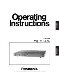
2COMPONENT SIDE<br />
<strong>CS</strong>-<strong>222</strong> PCB MAIN<br />
~~~~~~~~~~~~~~~~~~P/N 170150<br />
Location of Jumpers and Adjustments on PCB<br />
1. JP-1 and JP-2 Line Length Selection Jumpers<br />
Jumpers JP-1 and JP-2 allow the optimization of the hybrid null circuitry for excessive<br />
intercom cable lengths. JP-1 is for channel A and JP-2 is for channel B.<br />
The "S" position of the jumpers is for 'short' lines (200 - 500 feet). The "L" position is<br />
for lines in excess of 500 feet. The <strong>CS</strong>-<strong>222</strong> is shipped from the factory with the<br />
jumpers in the "L" position. For very short total line lengths (less than 200 ft) remove<br />
the jumper completely.<br />
2. JP-3 Interrupt Enable/Disable Jumper<br />
Jumper JP-3 allows the <strong>user</strong> to enable the "Stage Announce" mute function of active<br />
"Talks". Position "Y' is for yes to muting and "Nu for no. The <strong>CS</strong>-<strong>222</strong> is shipped from<br />
the factory with JP-3 in the wY position.<br />
3. Power Supply Voltage Adjustment<br />
0 Potentiometer P3 is provided for trim adjustment of the +30 volt power supply. If<br />
power supplies are intended to be paralleled on the same line their outputs should be<br />
as close as possible to each other for proper sharing of current.<br />
11/92 Rev. 1.2 Page 14
INSTALLATION / <strong>Clear</strong>-<strong>Com</strong> <strong>CS</strong>-<strong>222</strong> 2-<strong>Channel</strong> <strong>Main</strong> <strong>Station</strong><br />
F<br />
2.5 INTERCONNECTION SETUP 0<br />
After determining system configuration and channel assignment, pick a location for the<br />
<strong>CS</strong>-<strong>222</strong>; it can be anywhere as long as it is provided with a source of AC power. Check<br />
the Power Block on the rear panel for the proper AC voltage range. See section 2.3 on<br />
the page 12 if it needs changing.<br />
1. Use standard shielded mic cable (see section 2.2). ALWAYS AVOID SHARP<br />
BENDS IN THE CABLING; ALLOW AT LEAST 3 inches behind rack-mount<br />
units for cable extending from rear panels.<br />
2. Route all cables from the <strong>Main</strong> <strong>Station</strong> to the Remote <strong>Station</strong>s. Pin<br />
assignments on ALL 3-pin intercom connectors are:<br />
Pin 1 -- <strong>Com</strong>mon<br />
Pin 2 - +30 Volts DC<br />
Pin 3 - intercom Audio<br />
3. Route cables away from heavy AC power sources, such as lighting panels,<br />
electric motors, or power transformers.<br />
4. In permanent installations, BE SURE TO INSTALL THE SYSTEM IN<br />
ACCORDANCE WITH APPROVED LOCAL BUILDING CODE.<br />
5. If program monitoring is required, connect the external signal to the Program<br />
Input (3-pin female) connector on the <strong>CS</strong>-<strong>222</strong> rear panel. The station<br />
operator can hear the program in the headset mixed with intercom activity or<br />
the program can be sent to either intercom line. The program pre-amp's gain 0<br />
is switch-selectable (on the rear panel) for either mic level (-65 dBv nominal<br />
input signal) or line-level (-15 dBv nominal). The input is balanced and the<br />
impedance is 1 00K Ohms in the line position, 600 Ohms nominal in the mic<br />
position.<br />
6. If the Stage Announce function is to be used, connect to the Announce Output<br />
(3-pin male XLR) connector on the <strong>CS</strong>-<strong>222</strong> rear panel. This output is<br />
transformer balanced, 600 Ohms impedance, and an output level of 0 dBv. If<br />
the output is to be used as an unbalanced source connect one side to<br />
common (pin-2 to pin-1).<br />
If the SA relay is to be used, connect lo the appropriate screw lug terminals<br />
(NO or NC) depending on what action is needed for the external equipment<br />
to be controlled. The relay is a form C, Break before Make, contact. NOTE: the<br />
contact rating of the relays are 1A resistive at 24 VDC or 1/2A resistive<br />
at 120 VAC.<br />
7. Turn on power switch on the rear panel. The GREEN Power led on the front<br />
panel should illuminate. Plug in a headset, and set intercom, Program, and<br />
Sidetone levels as desired.<br />
NOTE ABOUT HEADSETS: The following is a description of a recommended headset.<br />
Mic Type ----- Dynamic Wiring: Pin 1 -- mic common<br />
Impedance -- 150-250 Ohms Pin 2-- mic hot<br />
Output -------- -55dB<br />
Headphone -- Dynamic<br />
Pin 3 -- headphone common<br />
Pin 4 -- headphone hot<br />
Impedance --- 50-2000 Ohms<br />
11/90 Rev. 1.0 Page 15
INSTALLATION / <strong>Clear</strong>-<strong>Com</strong> <strong>CS</strong>-<strong>222</strong> 2-<strong>Channel</strong> <strong>Main</strong> <strong>Station</strong><br />
TYPICAL <strong>CS</strong>-<strong>222</strong> SYSTEMS:<br />
K9-111A K9-1-1A KS-11iA KB-lilA<br />
RS C 75 9 CC-75B RS-502 CC-7YI RS-70 CC-7-I<br />
RSd -2 0VO50 C-2 MRW2C-22<br />
11/90 Rev. 1.0 Page 16
OPERATION / <strong>Clear</strong>-<strong>Com</strong> <strong>CS</strong>-<strong>222</strong> 2-<strong>Channel</strong> <strong>Main</strong> <strong>Station</strong><br />
SECTION 3 / OPERATION OF THE <strong>CS</strong>-<strong>222</strong> 2-CHANNEL INTERCOM STATION<br />
Normal operation of the <strong>CS</strong>-<strong>222</strong> only requires access to the front panel controls. For<br />
intercom operation set the Listen Level controls for each channel to desired level and<br />
press the Talk switches when talking. The rest of this section is a detailed description of<br />
each control.<br />
3.1 FRONT PANEL DESCRIPTION<br />
<strong>CS</strong>-<strong>222</strong> Front Panel<br />
1. Talk Buttons<br />
Each channel has its own illuminated "Talk" button for activating the microphone feed<br />
to a given channel. Mechanically the pushbutton is momentary in action, however<br />
electrically the button has dual action (momentary or latching) depending on how the<br />
button is pressed.<br />
LATCHING: Pressing the button quickly will "toggle" the "talk" function, alternately turning it on or<br />
off.<br />
MOMENTARY: Pressing the button for longer than 1/4 second will turn the button<br />
press into a momentary function such that when the button Is released the "Talk'<br />
function will turn oft. In any case the "Talk" function is activated all of the time the<br />
button is pressed.<br />
TALK INDICATION: The 'Talk" button will Illuminate dimly indicating when a "Talk" is<br />
activated.<br />
CALL INDICATION: The 'Talk" button will illuminate brightly when a "Call" signal is<br />
received on that channel.<br />
2. Call Buttons<br />
Each channel has its own "Call" button. Pressing the "Call" button at any time will<br />
send a "Call" signal on that channel regardless of the activation of the "Talk" circuit<br />
for that channel.<br />
The "Talk" button for that channel will illuminate brightly while the "Call" button is<br />
pressed indicating the presence of a "Call" signal on the line.<br />
11/90 Rev. 1.0 Page 17
OPERATION I <strong>Clear</strong>-Corn <strong>CS</strong>-<strong>222</strong> 2-<strong>Channel</strong> <strong>Main</strong> <strong>Station</strong><br />
3. Listen Level Controls<br />
0 Each channel has a separate "Listen Level" control. Listening Is always on and Is not<br />
controlled by any logic. To listen to a channel, turn up the appropriate control. To not<br />
listen to a channel, turn the control completely off.<br />
4. Side Tone Controls<br />
Each channel has a "Side Tone" null control. This control is used to set the amount of<br />
the microphone that is heard In the earphone from that channel.<br />
This control Is a true hybrid null control and therefore is sensitive to changes in line<br />
loading. For headphone use it is best to find the 'null' for a given channel and then<br />
rotate the control clockwise to obtain the desired side tone level.<br />
If an external speaker Is used providing a possible acoustic feedback path it will be<br />
necessary to use an almost complete 'null' of the side tone control.<br />
5. Remote Mic Kill Buttons<br />
It sometimes becomes desirable In an Intercom system to turn off all open microphones<br />
in a system. <strong>Clear</strong>-<strong>Com</strong> Series 500 beltpacks have the feature that if the DC power to<br />
the pack is removed momentarily, the microphone "Talk" circuits will be turned off.<br />
Pressing and holding the RMK button for several seconds will reset all open<br />
microphones at all Series 500 beltpacks on that channel.<br />
CAUTION: RMK CANNOT be used if power for a channel is derived from some<br />
place other than the local station. The RMK action momentarily shorts the power line<br />
of the affected channel. fiK Dily works fm a single MAIN station system,<br />
6. Program Enable Switches<br />
The <strong>CS</strong>-<strong>222</strong> has the ability to feed an external program signal to either of the two<br />
channels independently The "Program Enable Switch" allows the program to be<br />
turned ON, OFF, or ON with INTERRUPT.<br />
In the ON position the program Is fed to the channel under all conditions.<br />
In the OFF position the program is not fed to the channel.<br />
In the INT position the program is fed except when a "Talk" is activated to the<br />
channel. This "Program Interrupt" or IFB" function can be used for talent cueing and<br />
dressing room show monitor applications.<br />
7. Program Send Level Controls<br />
Each channel has a "Program Send Level" control that sets the amount of program<br />
being sent to that channel when the program is activated.<br />
8. Headset Connector<br />
The "Headset" connector is a XLR-4M wired for standard <strong>Clear</strong>-<strong>Com</strong> headsets.<br />
MICROPHONE: The <strong>CS</strong>-<strong>222</strong> is intended to work with a dynamic microphone of about<br />
200 ohms<br />
HEADPHONE: The <strong>CS</strong>-<strong>222</strong> is designed to drive a 50 to 1000 ohm headphone.<br />
<strong>Clear</strong>-<strong>Com</strong> headsets are 400 ohms for the singl muff and 200 ohms for the dual muff.<br />
05192 Rev. 1.1 Page 18
OPERATION / <strong>Clear</strong>-<strong>Com</strong> <strong>CS</strong>-<strong>222</strong> 2-<strong>Channel</strong> <strong>Main</strong> <strong>Station</strong><br />
9. Earphone Jack<br />
The jack marked "Earphone" provides an output intended to drive an extra earphone.<br />
This output is capable of driving an 8 ohm headphone or loudspeaker.<br />
10. Link Switch<br />
The switch marked "Link" on the right side of the unit allows the operator to "combine"<br />
channels A and B so that all stations can talk to each other. (Normally channels A and<br />
B are totally isolated and stations on one channel cannot talk to stations on the other<br />
channel.) When in the "A+B Link" operating mode, only the channel A controls<br />
operate. The channel B controls have no effect.<br />
NOTE: When the switch is in the "A+B" position the channels do not actually<br />
'combine'. What really happens is the three B channel connectors are simply<br />
internally disconnected from the B circuitry and connected to the A channel circuitry,<br />
putting all stations on the channel A party-line. This maintains all the correct line and<br />
station terminations.<br />
CAUTION: The LINK function will work properly at the main station that is providing<br />
the "line terminations" for the system. If there is more than one <strong>Main</strong> <strong>Station</strong> in the<br />
system equipped with a "LINK" switch, DO NOT ATTEMPT TO USE THE LINK<br />
SWITCH ON THE STATIONS THAT ARE NOT PROVIDING THE LINE<br />
TERMINATION. Both double line termination and station un-termination will result,<br />
causing significant sidetone mis-adjustments and possible feedback and oscillation.<br />
11. Program Monitor Control<br />
The "Program Monitorm volume control sets the amount of the program signal heard<br />
directly in the headphone. This control only affects what is heard in the headphone<br />
and does not affect "Program" feed to the intercom lines.<br />
12. Stage Announce Button<br />
The "Stage Announce" (SA) button allows the operator to instantly use the<br />
microphone input to directly talk to a system external to the intercom such as a paging<br />
speaker/amplifier in another room. A dry set of relay contacts on the rear panel is<br />
also available that can be used to activate external switching as needed when the<br />
"SA" button is pressed.<br />
Pressing the SA button momentarily disables any active "Talks". Active "Talk' circuits<br />
will be restored when the button is released. The "Talk" muting action can be<br />
defeated if desired by moving an internal jumper. (see section on internal options and<br />
adjustments)<br />
11/90 Rev. 1.0 Page 19
OPERATION / <strong>Clear</strong>-Corn <strong>CS</strong>-<strong>222</strong> 2-<strong>Channel</strong> <strong>Main</strong> <strong>Station</strong><br />
13. Power Supply LEDs<br />
There are two power supply status LEDs in the lower right hand corner of the front<br />
panel.<br />
NORMAL OPERATION: The GREEN LED is on by itself.<br />
OVERLOAD CONDITION: if the RED LED is on and the GREED LED pulses on shortly<br />
about every five seconds, the load is in excess of 1 ampere but there is not a direct<br />
short on the line.<br />
SHORT CONDITION: if the RED LED is on and the GREEN LED does not pulse on, the<br />
power line has a direct short on it.<br />
Lowering an excess load or removing a short will allow the automatic reset circuit to<br />
attempt to reset the power supply about once every four seconds, to restore normal<br />
operation to the power supply without operator intervention.<br />
SECTION 4 / TROUBLESHOOTING THE <strong>CS</strong>-<strong>222</strong> 2-CHANNEL INTERCOM STATION<br />
Symptom #1: System is non-operable: GREEN power led is not illuminated and the RED<br />
short led is not illuminated.<br />
CAUSE: Loss of AC power.<br />
* REMEDY: Plug unit into dependable AC source.<br />
CAUSE: Fuses could be blown.<br />
REMEDY: Replace fuse(s); If it blows repeatedly, probably the power supply has<br />
internal component failure.<br />
Symptom #2: The RED short led stays illuminated without the GREEN led pulsing on<br />
periodically.<br />
CAUSE: Shorted or mis-wired intercom cable.<br />
REMEDY: Remove cables, one at a time, from <strong>Main</strong> <strong>Station</strong> until faulty line Is located.<br />
Check for shorts between pins 1 and 2. When removing a possible short<br />
wait for several seconds to see if the automatic reset will clear itself.<br />
CAUSE: Defective Remote <strong>Station</strong>.<br />
REMEDY: Check Remote unit.<br />
Symptom #3: Excessive back-ground noise pick-up by microphone.<br />
CAUSE: Distance from mic to mouth is too far.<br />
REMEDY: Move closer to mic.<br />
CAUSE: Too many mics on in entire system.<br />
REMEDY: Turn off all unused mics. RMK can be used to kill all Series 500 belt-pack<br />
open mics.<br />
* CAUSE: Volume too high.<br />
REMEDY: Lower headset volume.<br />
11/90 Rev. 1.0 Page 20
TROUBLESHOOTING / <strong>Clear</strong>-<strong>Com</strong> <strong>CS</strong>-<strong>222</strong> 2-<strong>Channel</strong> <strong>Main</strong> <strong>Station</strong><br />
Symptom #4: Hum or buzz in system.<br />
CAUSE: inductive pickup caused by close proximity of <strong>Main</strong> or Remote station to<br />
power lines or transformers.<br />
REMEDY: Relocate offending unit.<br />
CAUSE: 10 Ohm chassis ground resistor (R224) is open.<br />
REMEDY: Check the DC resistance for 10 Ohms between the chassis and pin-1 of<br />
any intercom connector. R224 is located on the Rear Panel Connector<br />
Printed Wiring Board. If this condition happens It Is because the<br />
system ground came In contact with something "Hors with respect to<br />
the <strong>Main</strong> <strong>Station</strong> Earth ground. Should this occur, we recommend<br />
you carefully check the system ground and AC distribution In the<br />
area.<br />
NOTE: THIS IS A POTENTIALLY DANGEROUS SITUATION; IF IT<br />
OCCURS, A SHOCK HAZARD MAY EXIST BETWEEN THE METAL<br />
BOOM OF A HEADSET AND GROUND.<br />
CAUSE: inductive pick-up by headset mic; check by switching mic on and off.<br />
REMEDY: Move mic away from "hum field".<br />
Symptom #5: System feedback.<br />
CAUSE: Acoustical.<br />
REMEDY: Volume too high at one station.<br />
REMEDY: <strong>Two</strong> or more speaker stations have mics on simultaneously.<br />
REMEDY: Headset-mis-wired. Rewire headset connector.<br />
REMEDY: Headset laying on table and microphone on. Turn mic off.<br />
REMEDY: Headset quality. Some headsets have poor isolation between the<br />
microphone and earphone. Adjust sidetone.<br />
CAUSE: Electrical.<br />
REMEDY: Check Termination.<br />
REMEDY: Check sidetone levels.<br />
REMEDY: A headset extension cord was used. Headset extension cords must be<br />
used with great care and are not recommended.<br />
Symptom #6: Audio sounds low and distorted and the Call light stays on.<br />
CAUSE: An ultrasonic oscillation is present.<br />
REMEDY: Headset mis-wired. Rewire headset connector.<br />
REMEDY: A headset extension cord was used. Headset extension cords must be<br />
used with great care and are not recommended.<br />
11/90 Rev. 1.0 Page 21
PARTS LISTING / <strong>Clear</strong>-<strong>Com</strong> <strong>CS</strong>-<strong>222</strong> 2-<strong>Channel</strong> <strong>Main</strong> <strong>Station</strong><br />
SECTION 5 / Parts List for <strong>CS</strong>-<strong>222</strong> 2-CHANNEL INTERCOM STATION<br />
CC aF A Descritiaon X1.<br />
240039 Bracket, Hardware for Handle 2<br />
240020 Button, Red for C&K Switches 2<br />
240021 Button, Black for C&K Switches 3<br />
210233 Connector, Power Entry Module 1<br />
610022 Cord, Power 1<br />
480090 CMOS IC, MC14584B Hex Schmitt Trigger 1<br />
480092 CMOS IC, DG211CJ Quad Analog Switch 1<br />
480112 CMOS IC, 4001 Quad 2 input NOR Gate 1<br />
480171 CMOS IC, 4013 Dual D Type Flip-Flop 1<br />
480000 Diode, 1N4148, Signal 22<br />
480001 Diode, 1N4001, Rect. 1A 50V PIV 1<br />
480005 Diode, 1N5401, Rect. 3A 100V PIV 4<br />
480026 Diode, Zener, 1 N957B 6.8V 5% .4W 2<br />
480038 Diode, Zener, 1N5231B 5.1V .5W 1<br />
480053 Diode, Zener, 1N5245B 15V .5W 1<br />
480172 Diode, Zener, 1 N5251 B 22V 5% .5W 1<br />
520035 Fuse, 1/4A SLO-BLO 20MM 2<br />
240015 Knob, Volume with 1/8" shaft 3<br />
240038 Handle, Black 1<br />
390005 Lamp, Incandescent EL3522 (Talk SW) 2<br />
390038 LED, Red Square (Short LED) 1<br />
390039 LED, Green Square (Power Good) 1<br />
810133 Manual, Instnuction 1<br />
480012 OP-AMP, LM384 Power 1<br />
480175 OP-AMP, LM833A Dual Low Noise 1<br />
480070 OP-AMP, NE5532 Dual Low Noise 4<br />
480021 OP-AMP, NE5534A Low Noise 1<br />
470019 POT, 50K Trim Vert. PC Mount (Prog Lev.) 2<br />
470029 POT, 2K Trim Horz. PC Mount (Volt Adj.) 1<br />
4 7 00t-1 POT, 50 PC Mount (Volume) 3<br />
470063 POT, 5K Trim Horz. PC Mount (Sidetone) 2<br />
450004 Relay, SPDT 24VDC 1<br />
240010 RubberFoot 4<br />
240058 Shaft, Trimpot (Sidetone) 2<br />
510028 Switch, SPDT Pushbutton (Stage Announce) 1<br />
510043 Switch, SPDT Pushbutton (Call) 2<br />
510095 Switch, SPDT Pushbutton 6A (RMK) 2<br />
510094 Switch, SPDT Toggle (Link) 1<br />
510096 Switch, SP3T Toggle (Program) 2<br />
510090 Switch, DPDT Slide (Term. & Prog Gain) 3<br />
510093 Switch, 4PDT Illuminated Pushbutton (Talk) 2<br />
560015 Transformer, Audio (Stage Announce) 1<br />
560016 Transformer, Power 1<br />
480047 Transistor, 2N4401 2<br />
480061 Transistor, 2N5486 N <strong>Channel</strong> JFET 1<br />
480069 Transistor, 2N5639 N <strong>Channel</strong> JFET 1<br />
480052 Transistor, MPS-A05 5<br />
480004 Transistor, MPS-A13 6<br />
480050 Transistor, MPS-A55 3<br />
480008 Transistor, MPS-A63 2<br />
480173 Transistor, MTA30N06EL Power MOSFET 60V 30A 1<br />
11/90 Rev. 1.0 Page 22
--------~ ~ ~~----- - -Lf IL1 fV<br />
---- AA<br />
a s -- ~~~~~~~~~~~~~~------<br />
---- --------- ---- ---- Y - ---- --- 0 >--<br />
-<br />
gS t i i N T<br />
O ' ark<br />
CH 2iS 9<br />
U;~~~~~~~~~<br />
W N' HW ~~~~~~~~~~~~~~~~~~~~~~~~~~~~~~~~~~~~~~~~~~~C<br />
| Lady,,. s4S¢1,,4~~~~~~~~<br />
8 p | $<br />
t ; S~~a vp<br />
o s BS tYX__ |~~~d<br />
i~~~~~~~~~~~~~~~~~~~~~~~~~~~~~~H >0-<br />
s , .~~~~~~~~~<br />
of~~~~~~~~~~<br />
_ _ _~~~~~~~~~~~~-