JVC DT-V24L1DU 24 inch Multi-Format LCD Monitor user ... - Talamas
JVC DT-V24L1DU 24 inch Multi-Format LCD Monitor user ... - Talamas
JVC DT-V24L1DU 24 inch Multi-Format LCD Monitor user ... - Talamas

Create successful ePaper yourself
Turn your PDF publications into a flip-book with our unique Google optimized e-Paper software.
Daily Operations / Connections (cont.)<br />
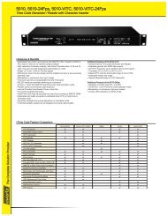
7 Rear panel<br />
<strong>DT</strong>-V<strong>24</strong>L1 and <strong>DT</strong>-V20L1 do not have 9 and p.<br />
AC inlet<br />
Power input connector. Connect the<br />
provided AC power cord to an AC outlet.<br />
• Attach the provided power cord holder<br />
to prevent accidental disconnection of<br />
the AC power cord (☞ the right).<br />
Security slot<br />
Install a security wire to this slot.<br />
The illustration of the monitor is of <strong>DT</strong>-V<strong>24</strong>L1D.<br />
CAUTION<br />
It is recommended not to use the power cord holder when installing the monitor in a monitor rack etc. where you cannot easily pull out the AC<br />
power cord from an AC outlet.<br />
Attaching the Power Cord Holder<br />
• The provided power cord holder prevents accidental disconnection of the AC power cord from the AC inlet.<br />
• The power cord holder consists of two parts, a case and a cover.<br />
1 Attach the power cord holder case<br />
around the AC inlet on the rear<br />
of the monitor with two screws<br />
(provided).<br />
CAUTION<br />
Use only the provided screws.<br />
2 Attach the power cord holder cover<br />
to the AC power cord.<br />
CAUTION<br />
A different plug shape will result in the cover<br />
being attached to a different position.<br />
3 Plug in the AC power cord<br />
to the AC inlet, and attach<br />
the power cord holder<br />
cover to the case.<br />
CAUTION<br />
Make sure the plug will not be<br />
pulled out after the cover is<br />
attached.<br />
NOTE<br />
To detach the cover, release<br />
the tab.<br />
Tab<br />
8<br />
1 REMOTE (MAKE/TRIG.) terminal (RJ-45)<br />
Terminal for controlling the monitor by an external control.<br />
☞ “External Control” on page 14<br />
2 REMOTE (RS-485) terminals (RJ-45)<br />
Terminals for controlling the monitor by an external control.<br />
☞ “External Control” on page 14<br />
3 REMOTE (RS-232C) terminal (D-sub 9-pin)<br />
Terminal for controlling the monitor by an external control.<br />
☞ “External Control” on page 14<br />
4 VIDEO (INPUT 1, INPUT 2) terminals (BNC)<br />
Input (IN) and output (OUT) terminals for the composite<br />
signals.<br />
5 COMPO./RGB (G/Y, B/PB/B-Y, R/PR/R-Y) terminals<br />
(BNC)<br />
Input (IN) and output (OUT) terminals for the analog<br />
component (color difference) or analog RGB signals.<br />
• Select the signal type in “COMPO./RGB SEL.”<br />
corresponding to the type of the input signal (☞ page 10).<br />
6 EXT.SYNC (CS) terminals (BNC)<br />
Input (IN) and output (OUT) terminals for the external<br />
composite sync (Cs) signals.<br />
• To use these terminals, set “SYNC INPUT SEL.” to “EXT.”<br />
☞ “SYNC FUNCTION” on page 11<br />
NOTE<br />
• The terminals are for all VIDEO (INPUT 1), VIDEO (INPUT 2) and<br />
COMPO./RGB.<br />
• When an external sync signal is input, external synchronization<br />
has priority over all VIDEO 1, VIDEO 2 and COMPO./RGB input.<br />
• The setting of “SYNC INPUT SEL.” is memorized for each input.<br />
7 AUDIO ASSIGN (IN 1, IN 2) terminals (pin jack)<br />
Input terminals for the analog audio signals.<br />
• Select the video input to assign the audio signal<br />
in “AUDIO1 ASSIGN.” or “AUDIO2 ASSIGN.” (☞<br />
“AUDIO SETTING” on page 11).<br />
8 AUDIO ASSIGN (MONITOR OUT) terminals (pin<br />
jack)<br />
Output terminals for the analog audio signal.<br />
• The terminals output the audio signal through AUDIO<br />
ASSIGN (IN 1) or AUDIO ASSIGN (IN 2) terminals<br />
when you select the video input you have selected<br />
for “AUDIO1 ASSIGN.” or “AUDIO2 ASSIGN.” in<br />
“AUDIO SETTING” (☞ page 11).<br />
• The EMBEDDED AUDIO signal is decoded into an<br />
analog signal, then emitted.<br />
NOTE<br />
• The signal is output from this terminal only when the monitor<br />
is on.<br />
• The EMBEDDED AUDIO signal has priority over the audio<br />
signal input to AUDIO ASSIGN (IN 1) or AUDIO ASSIGN (IN<br />
2) terminals when “SDI 1” or “SDI 2” is selected for “AUDIO1<br />
ASSIGN.” or “AUDIO2 ASSIGN.” and the EMBEDDED<br />
AUDIO signal is input to HD/SD SDI (IN 1) or HD/SD SDI<br />
(IN 2) terminal.<br />
9 HD/SD SDI (IN 1, IN 2) terminals (BNC)<br />
Input terminals for the HD SDI and SD SDI signals.<br />
The terminals accept the following signals.<br />
• SMPTE292M HD SDI signal<br />
• SMPTE259M SD SDI signal<br />
• EMBEDDED AUDIO signals* including up to 12 audio<br />
channels with the sampling frequency of 48 kHz.<br />
NOTE<br />
The types of signals coming through the IN 1 and IN 2 terminals<br />
are automatically recognized—HD SDI or SD SDI signal. Note,<br />
however, that input is not changed automatically.<br />
p HD/SD SDI (SWITCHED OUT) terminal (BNC)<br />
Output terminal for the HD SDI and SD SDI signals.<br />
• The SDI signal of the current input (SDI 1 or SDI 2) is<br />
re-clocked and output.<br />
NOTE<br />
• When the input other than SDI 1 or SDI 2 is selected, the SDI<br />
signal of the input selected last time is re-clocked and output from<br />
this terminal.<br />
• The signal is output from this terminal only when the monitor is<br />
on.<br />
q DVI-D (HDCP) terminal<br />
Input terminal for the DVI-D signal.<br />
• Select the signal type in “DVI INPUT SEL.” corresponding<br />
to the type of the input signal (☞ page 10).<br />
*Using the audio level meter (<strong>DT</strong>-V<strong>24</strong>L1D and <strong>DT</strong>-V20L1D only)<br />
You can check the conditions of the current EMBEDDED<br />
AUDIO signals in the audio level meter. The setting for the<br />
level meter is selected in “LEVEL METER SETTING” (☞<br />
“AUDIO SETTING” on page 11).